By Baiye

With the commercial promotion of non-volatile memory (NVM) products, we are increasingly interested in their potential for large-scale popularization in cloud-native databases. X-Engine is an LSM-tree storage engine developed by the PolarDB new storage engine team of Alibaba Cloud database products division.
Currently, it provides external services on the Alibaba Cloud PolarDB product series. Based on X-Engine and combined with the advantages of non-volatile memory (NVM), we took into account its limitations and redesigned and implemented the main data structures of the storage engine in memory, transaction processing, persistent memory allocator, and other basic components. Finally, we realized high-performance transaction processing without recording pre-written logs. This reduced the write amplification of the system as a whole and improved the crash recovery speed of the storage engine.
The research results were published in VLDB2021 as the paper "Revisiting the Design of LSM-tree Based OLTP Storage Engine with Persistent Memory". We hope this paper could contribute to both subsequent research and application implementation. As a team that continues to dive deep into the basic technologies of databases, we have researched transaction storage engines, high-performance transaction processing, new memory devices, heterogeneous computing devices, and AIforDB.
Persistent Memory (PM) not only provides larger capacity and lower power consumption than DRAM but also has many characteristics such as byte addressing. We aim to use PM to greatly increase the memory capacity and reduce the static power consumption of the device while providing persistent byte addressing and other features to simplify the design of the system. It has brought new opportunities for the design of the database storage engine. Optane DCPMM adopts the product form of DDR4 DIMM, which is also called Persistent Memory Module (PMM). Currently, DCPMM provides three capacity options: 128 GB, 256 GB, and 512 GB. The actual usable capacity is 126.4 GB, 252.4 GB, and 502.5 GB, respectively. Optane DCPMM now only applies to Intel Cascade Lake processors. Like traditional DRAM, it is connected to processors through Intel iMC (integrated Memory Controller). Although DCPMM provides the same byte addressing capability as DRAM does, its I/O performance is quite lower than that of DRAM. This is mainly reflected in media access granularity, cache control, concurrent access, and cross-NUMA node access. If you are interested, please view the first two references listed at the end of this article.
X-Engine is an OLTP database storage engine based on LSM-tree architecture. Its implementation architecture is shown in Figure 2. A single database can be composed of multiple LSM-tree instances (called subtable). Each instance stores a table, index, or table partition. For details, please refer to the paper [3] of SIGMOD in 2019. LSM-tree divides data into multiple levels that grow according to a certain proportion. These levels are at the memory and disk. Data flows from the upper level to the lower level through compaction. DRAM is volatile, so it cannot hold data without power. It uses Write Ahead Log (WAL) to write the data to the disk in advance for persistence. Then, the data in the memory is flushed to or merged into the disk before clearing the corresponding WAL. In a typical design, the data in memory is usually implemented by using a skiplist. When the size of skiplist exceeds a certain threshold, it will be frozen (Switch operation and immutable memory table in the figure) and dumped to disk. Then, a new memory table is created. Data of each level in the disk is stored in multiple Sorted String Tables (SSTs). Each SST is equivalent to a B tree. Usually, the ranges of key-value pairs of different SSTs in the same level do not overlap. However, in the system, in order to speed up the flush operation of memory tables, the SSTs of some levels are usually allowed to overlap. For example, in LevelDB and RocksDB, Level 0 is allowed to overlap. The problem is that out-of-order data layout in Level 0 will reduce the reading efficiency.
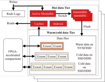
Figure 2 Main architecture of X-Engine
The design of existing OLTP storage engines based on LSM-tree architecture usually has the following problems: (1) WAL is located in the critical write path. In particular, to meet ACID of transactions, WAL is usually written to the disk synchronously, thus reducing the write speed. Besides, although an excessively large memory table can improve the system performance, it will cause the WAL to be too large, which will affect the recovery time of the system. This is due to the volatility of DRAM. (2) Data blocks in level 0 are usually allowed to be out of order to speed up data flushing in the memory. However, excessive accumulation of out-of-order data blocks seriously affects the read performance, especially the range read performance. It seems that persistent byte-addressable PM can be used to implement persistent memory tables to replace volatile memory tables in DRAM, thereby reducing the overhead of maintaining WAL. However, in fact, due to the features of PM itself, there are still great challenges in implementing efficient persistent indexes, including PM memory management. In addition, the current PM hardware can only maintain atomic writing of eight bytes. As a result, in order to implement atomic writing semantics, traditional methods still need to introduce additional logs (also called PM internal logs).
In order to deal with these challenges, the paper designs an efficient PM memory manager Halloc for LSM-tree-specific optimization. It also proposes an optimized PM-based semi-persistent memory table to replace the memory table in DRAM of the traditional scheme. It uses the lock-free, log-free algorithm (ROR) to remove ACID of the traditional scheme that relies on WAL to maintain transactions. It designs a globally ordered Global Index to make the index layer persistent and an in-store merge strategy to replace the level 0 of the traditional scheme. It improves query efficiency and reduces CPU and I/O overheads for data maintenance in level 0. The main improvements in the paper are shown in Figure 3, where mem represents active memtable, imm represents immutable memtable, and the prefix "sp-" represents semi-persistence. These designs bring the following three benefits: (1) They prevent WAL writing or PM programming library from introducing additional internal logs, so we can realize faster writing; (2) The data in PM is directly persisted, avoiding frequent disk flushing and merge operations in level 0, and the capacity can be set larger so we do not have to worry about the recovery time; (3) Data in level 0 is globally ordered, and there is no need to worry about data accumulation in level 0.
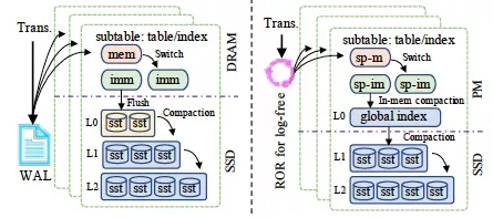
Figure 3 Comparison between the main scheme in the paper and traditional schemes
| No persistence | Semi-persistence | Full persistence | |
| Performance | High | Middle | Low |
| Recovery time | x | N/A | Fast |
Update and add operations of persistent indexes usually involve multiple small random writes exceeding eight bytes in PM. Therefore, overhead for maintaining consistency and handling write amplification caused by random writes is introduced. The design of PM-based indexes can be divided into three categories. No persistence means that PM is used as DRAM. This method can ensure that the index has the highest performance, but the data is lost while the power supply fails. Full persistence is to index all data (index nodes and leaf nodes) for persistence, such as BzTree and wBtree. This method can achieve rapid recovery, but the persistence cost is usually high, and the performance is usually low. One reasonable way is to persist only the necessary data in exchange for performance and recovery time. For example, NV-Tree and FPTree persist only leaf nodes, and index nodes are rebuilt upon reboot. In the LSM-tree structure, the memory table is usually small, so it is more appropriate to adopt the semi-persistent index design. In the paper, two methods are used to reduce the overhead of maintaining persistent indexes.
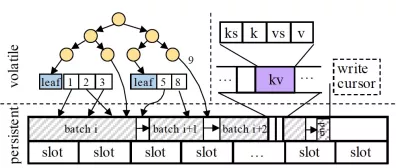
Figure 4 Structure of semi-persistent memory table
Only leaf nodes are persisted. In actual application, LSM-tree-based OLTP engines on the cloud usually do not design large memory tables, typically 256 MB. This is mainly due to the following two reasons: (1) Cloud users usually purchase database instances with small memory capacity; (2) LSM-tree need to maintain small memory tables to ensure fast disk flushing. For a 256-MB memory table, we found that the overhead of recovering non-leaf nodes when only leaf nodes are persistent is less than 10 milliseconds. This recovery time is fast enough, considering the database system under study. The index is designed to use serial numbers and user key separation to speed up key lookup and meet Multi-Version Concurrent Control (MVCC) of the memory table. As shown in Figure 4, for values with only one version (9), a pointer to the specific location of the PM will be stored directly in the index. For values with multiple versions, a scalable array is used in the design to store the serial numbers of multiple versions and their specific pointers. Since the index is volatile, the keys are not explicitly stored in the index. The index is rebuilt by scanning the key-value pairs in the PM upon reboot.
Batch sequential write is adopted to handle write amplification. In PM, small random writes are converted by the hardware controller into random large writes of 256 bytes. This is what we call write amplification, which consumes the bandwidth resources of the PM hardware. As the memory table is designed to be in a sequentially appended write mode, in order to avoid write amplification, the semi-persistent memory table packages small writes into large blocks (called WriteBatch). It sequentially writes the WriteBatch into PM and then writes the records therein into the volatile index. As shown in Figure 4, batch represents a WriteBatch. The slot records the ID of the zone object allocated from the Halloc allocator.
Indexes in memtable referred to in this article do not need to be persisted. Therefore, we only need to ensure the atomic persistence of data. Although PM can provide persistent byte-addressable write, it can only provide eight bytes of atomic writes (only refer to Intel Optane DCPMM). Therefore, write operations larger than eight bytes have the risk of torn write. The traditional solution is to use log-as-data method to ensure atomic writing. As shown in Figure 5, log items are written sequentially, and the 8-byte head pointer is updated after each log item is written. Since the atomicity of head update can always be ensured by hardware, log items before the head can be regarded as successful writing. Log items after the head have some write risks and are discarded when restarted.
There are two problems with this scheme: (1) Logs can only be written sequentially. This does not facilitate the capability of parallel writing of multi-core systems; (2) The existence of data with different lifecycles in the log items makes it hard to revoke log items. As shown in Figure 5, data in log1 is written into three LSM-tree instances, and the time for memtable flushing is different in different LSM-tree instances. One LSM-tree instance may have fewer data written. Then the disk flushing cycle is longer, causing log1 cannot be effectively revoked for a long time and reducing the memory utilization of PM.
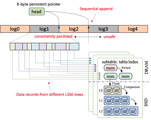
Figure 5 Problems with traditional schemes
To solve these problems, the paper proposes ROR algorithm. It uses ChainLog data structure to separate the data life cycle and uses the lock-free ring to realize concurrent writing of logs. In order to further reduce random write for PM to improve write performance, the ROR algorithm uses batches to merge small ChainLog into larger data blocks. As shown in Figure 6, ChainLog guarantees atomicity of data of any size written to PM. Batching is used to aggregate and write of small transaction cache in batch to PM to reduce random write of PM. Concurrency ring provides lock-free pipeline write (for ChainLog only) to PM to improve the scalability of multi-core systems.
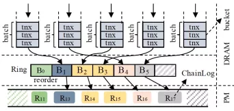
Figure 6 Overall framework of the ROR algorithm
For a transaction to be submitted, it is first encapsulated into a WriteBatch. One or more WriteBatches are further encapsulated into a ChainLog to be written to the PM in batch. In this article, the original two-phase lock (2PL) and MVCC of the LSM-tree are still used. As shown in Figure 6, ROR uses a fixed-size, adjustable concurrent bucket to control concurrent write. The first thread that enters a bucket becomes the leader thread. It is responsible for executing specific write. The rest threads that enter the bucket become follow threads. Leader aggregates WriteBatch of itself and all follow threads belonging to the bucket into a larger WriteBatch for actual writes.
One important aspect of ROR is ChainLog. It adds the domain for identifying log lifecycle and the domain marking the write location to the 8-byte head. We can locate which ChainLog has been partially written through the domain, so we can discard it on reboot. The domain of the log lifecycle allows us to isolate data written to different LSM-tree instances in ChainLog by writing it to different memory spaces. ChainLog is always written serially from a high-level perspective, that is, a ChainLog item is persisted only when all previous ChainLogs have been persisted in PM. Serialized submission allows us to check only the last ChainLog item during system recovery. We need to check whether the write to the last ChainLog involves partial write.
First, let's consider the separation of data lifecycles. A readily understandable approach is to set up a separate head pointer for each LSM-tree instance. As shown in Figure 7, each head is responsible for indicating the write location of its corresponding memory space. Different memory spaces are separated from each other and have independent lifecycles. The memtable in the corresponding LSM-tree can be revoked immediately after being flushed without waiting for other LSM-tree instances. However, this approach has an obvious problem. A single transaction may be written to multiple LSM-trees. Therefore, a single update involves the update of multiple heads, and the hardware cannot guarantee the atomicity of the write.
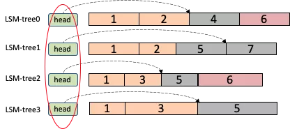
Figure 7 Log item lifecycle
To solve this problem, ROR adds the following position information indicating the write position to the 8-byte head in each LSM-tree instance. The gidx in Figure 8 is the original 8-byte head pointer. The first four bytes in the gidx pointer are used to record the last writing position, and the following four bytes are used to record the current writing position. In every four bytes, six bits are used to record the slot of the memtable, and 26 bits are used to record the offset of the corresponding slot. A total of 4 GB of space can be addressed. The data written by a ChainLog item is divided into n subitems, and each subitem is written to the corresponding LSM-tree instance. The number of subitems and the LSN of the current ChainLog are recorded in each subitem.
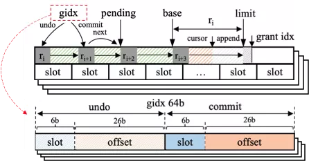
Figure 8 Diagram of gidx structure
Figure 9 shows the process where ChainLog2 (R2) has been successfully submitted and R3 is waiting to be submitted. However, an abnormal power failure occurred in the system during R3 submission. As a result, the subitem r31 of R3 is successfully submitted while r32 fails to be submitted. When the system recovers, by scanning the last ChainLog subitems in all LSM-tree instances, we can find that the current maximum LSN is 3. r31 has been successfully submitted, and the number of subitems recorded in it is 2. However, r32 has not been successfully written. Therefore, the gidx of its LSM-tree instance 1 will be rolled back (through right shift operation). After the rollback, r31 is discarded and the LSN falls back to 2. At this point, the system returns to the global consistency state.
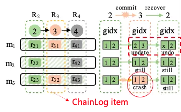
Figure 9 Diagram of recovery after power failure
ChainLog needs to meet the serialized write semantics. This is to ensure that only the last ChainLog subitems of all LSM-trees need to be scanned during recovery to correctly establish a globally consistent state. One way to ensure serialized writing semantics is serial writing, but this method cannot take advantage of the high concurrent write feature of multi-core platforms. In essence, it conforms to the idea of creating sequences before writing. The ROR algorithm uses post-write sequencing, that is, each thread does not pay attention to order when writing. In this process, the ROR algorithm dynamically selects the master thread to collect and sequence the currently finished ChainLogs. Sequencing only involves the update of ChainLog metadata. Therefore, the write performance is greatly improved. The master thread exits after sequencing is completed, and the ROR algorithm continues to dynamically select other master threads to repeat the process. This process is controlled by the lock-free ring and lock-free algorithm of dynamic master selection. For more details, please refer to papers related to it.
Global Index (GI) is mainly used to maintain a variable indexed data layer in PM to replace disordered data of level 0 in the disk. To simplify implementation, GI uses the same volatile index as the memory table does and places the data in the PM. Since the memory table also places data in the index, no data copy is required when the data of the memory table is transferred to the GI. We only need to make the pointer in the GI index point to the data in the memory table. It is worth noting that GI can use any range index or persistent index to improve the recovery speed of the system. Since the update of GI does not require the design of multiple KV updates and transactional requirements of writing, the existing lock-free and log-free range index can be applied to GI.
In-memory merge: It refers to the merge from the memory table to the GI. GI uses the same index design as a memory table does, that is, key-value pairs are stored in the PM. Leaf nodes use scaling arrays with data versions to store data that belongs to the same key. During in-memory merge, if GI does not contain identical keys, the key is inserted into GI. If the key already exists, we need to check multiple versions of the key in GI, and, if necessary, perform multi-version clearing to save memory space. Since the key-value pairs in the PM are managed by Halloc, the memory release of the key-value pair granularity is not allowed. When the in-memory merge is completed, only the memory of the memory table is released. The PM memory of the GI is released in batch only when all key-value pairs in the GI are merged to the disk.
Snapshot: Snapshots ensure that when GI is merged to the disk, in-memory merge operation can be performed at the same time to avoid blocking frontend operations. In the snapshot implementation, GI freezes the current data and creates a new index internally to store the merged data from the memory table. This design avoids blocking frontend operations but causes additional query overhead as the query may involve two indexes.
PM-to-disk compaction: Since the GI data merged to the disk is immutable and globally ordered, PM-to-disk compaction does not hinder frontend operations. Besides, the globally ordered nature of GI allows the compaction operation to be parallelized by range and separation, thus speeding up PM-to-disk compaction.
Data consistency: PM-to-disk compaction involves changes of the database state. Data consistency issues may occur during system crashes. To solve this problem, this article suggests ensuring the data consistency of database state changes by maintaining manifest logs in the disk. The description log is not in the critical path of frontend write, so it does not affect the performance of system writing.
Halloc is an LSM-tree-specific PM memory allocator. It uses three key technologies to solve the problems of low efficiency and fragmentation in traditional general PM memory allocators. These technologies include object pool-based memory reservation, application-friendly memory management, and unified address space management. Its main architecture is shown in Figure 10. Halloc divides its memory addresses and manages its internal metadata by directly creating DAX files. Its address space is divided into four areas to store Halloc metadata, subtable metadata, memory table metadata, and memory blocks reserved for other usages.
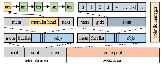
Figure 10 Overall architecture of Halloc memory allocator
Object pool-based memory reservation. Halloc reduces memory fragments in PM by statically reserving fixed-size object pools and memory space whose addresses do not overlap each other. Each object pool contains a metadata area to record the allocation of objects. The persist linked list (freelist) is used to track idle objects and fixed-size object areas. freelist size is explicitly specified when the object pool is created. Since the operation on the persistent linked list involves multiple discontinuous PM write operations larger than eight bytes, there is a risk of data inconsistency. Traditional solutions use internal logs such as PMDK and Mnemosyne to ensure the transactional property of operations. However, additional log overhead will be introduced. In order to eliminate the log overhead, this article proposes the following solution to ensure the data consistency of freelist operations.

Figure 11 Internal structure of freelist
As shown in Figure 11, freelist stores data sequentially in the memory space, which includes a metadata area for recording allocation, an index area for indexing idle objects, and an object area for storing specific objects. For each object, there is a corresponding 8-byte index. The highest bit of each index is used to mark the persistence state of the object to ensure atomic allocation and release of objects. freelist provides four interfaces for the allocation and release of an object: Get is used to obtain an object from freelist. Commit is used to notify Halloc that the object has been initialized and can be removed from freelist. Check is used to detect whether an object has been persisted to avoid object reference error during crash restart. Release is used to release an object. The core idea is, by setting the persistence mark in the index of an object, leaked objects can be detected at the time of reboot.
For the reboot recovery of the object pool, Halloc first scans the objects of freelist and marks them in bitmap. Then, it scans the index domain to confirm whether the object is reachable in freelist. Unreachable objects will be revoked. This design increases the overhead of restarting to some extent, but in fact, the scan is very fast. It only takes a few milliseconds to scan millions of objects in tests. The restart overhead is negligible in the system under study.
Application-friendly memory management. Halloc provides two object pool services for LSM-tree: custom object pools and zone object pools. This design is mainly based on the unique append write and batch revoking operations of LSM-tree for memory usage. It greatly simplifies memory management. In terms of custom object pools, as shown in Figure 8, Halloc maintains memtable and subtable pools for storing the table metadata and subtable metadata of engines, respectively. A subtable object contains a linked list to record all memtable objects it owns (linked through memlist). The first memtable object is the active memory table, and the rest are frozen memory tables. Each memtable object indexes a limited number of zone objects. Each zone object records specific memtable data. The zone object pool is a Halloc built-in object pool for applications to manage their own memory in their own way. This design is mainly because the custom object pool can only store limited and fixed-size objects. Since Halloc is not aimed at general PM memory allocation, for the management of objects of variable size and number, applications need to implement their own memory management scheme based on zone object pool.
Unified address space management. To facilitate the joint management of volatile and persistent memory, Halloc supports both persistent memory allocation and volatile memory allocation in the address space of a single DAX file. This greatly simplifies the use of PM resources. Similar to libmemkind, Halloc also applies to jemalloc to take over the allocation of volatile memory of specific variable sizes. The difference is that Halloc uses zone as the basic memory management unit of jemalloc. In other words, jemalloc always obtains zone objects from the zone pool for further refined management. The objects allocated from the zone pool do not call Commit anymore, so all allocated zone objects will be revoked after the system reboots. A major limitation of this design is that the size of user-allocated volatile memory cannot exceed the size of a single zone because the zone object pool can only guarantee the continuity of the memory address of a single zone. For larger memory allocation, users can choose to split and allocate it multiple times or use a custom object pool for static allocation if the object size is fixed and its number is limited.
Continue reading Part 2 of this article to see the experimental results of the X-Engine.
ApsaraDB - June 7, 2022
ApsaraDB - December 21, 2022
ApsaraDB - April 13, 2020
ApsaraDB - December 26, 2023
Alibaba Clouder - November 6, 2018
ApsaraDB - November 17, 2020
 PolarDB for PostgreSQL
Alibaba Cloud PolarDB for PostgreSQL is an in-house relational database service 100% compatible with PostgreSQL and highly compatible with the Oracle syntax.
Learn More PolarDB for Xscale
Alibaba Cloud PolarDB for Xscale (PolarDB-X) is a cloud-native high-performance distributed database service independently developed by Alibaba Cloud.
Learn More PolarDB for MySQL
Alibaba Cloud PolarDB for MySQL is a cloud-native relational database service 100% compatible with MySQL.
Learn More ApsaraDB for Cassandra
A database engine fully compatible with Apache Cassandra with enterprise-level SLA assurance.
Learn MoreMore Posts by ApsaraDB