By Wang Menghai (Musu), Technical Expert at Alibaba
Kubernetes is the most popular automatic container O&M platform and it features flexible declarative container orchestration. This article describes the basic scheduling framework, scheduling process, major filters, and Score algorithm implementation in Kubernetes 1.16, and two methods used to implement custom scheduling.
Kubernetes is the most popular automatic container O&M platform. The Kubernetes scheduler is essential for container orchestration in Kubernetes. This article focuses on the Kubernetes scheduler of Kubernetes v1.16.

Currently, the launch configuration of the scheduler policy used by the Kubernetes scheduler supports three formats: configuration file, command-line parameter, and ConfigMap. The scheduler policy can be configured to specify which predicates, priorities, extenders, and plugins of the latest Scheduler Framework are used in the main scheduling process.
Upon startup, the Kubernetes scheduler fetches data required for scheduling from the Kubernetes API server through an informer by using the List and Watch APIs. This data includes pods, nodes, Persistent Volumes (PVs), and Persistent Volume Claim (PVC). Such data is preprocessed as the cached data of the Kubernetes scheduler.
The Kubernetes scheduler inserts the pods to be scheduled into a queue through an informer. These pods are cyclically popped out from the queue and pushed into a schedule pipeline.
The schedule pipeline is divided into the schedule thread, wait thread, and bind thread.
The filter phase selects the nodes consistent with pod spec. The score phase scores and sorts the selected nodes. The reserve phase puts a pod in the node cache of the optimal sorted node, indicating that the pod is assigned to this node. In this way, the next pod that waits for scheduling knows the previously assigned pod when the node is filtered and scored.
Pods are scheduled one by one only in the schedule thread and are scheduled in the wait thread and bind thread in an asynchronous and parallel manner.
This section describes how the Kubernetes scheduler works. The following figure shows the Kubernetes scheduler workflow.

The scheduling queue has three subqueues: activeQ, backoffQ, and unschedulableQ.
When the Kubernetes scheduler is started, all pods to be scheduled enter activeQ, which sorts the pods based on their priorities. The schedule pipeline fetches a pod from activeQ for scheduling. If scheduling fails, the pod is put into unschedulableQ or backoffQ depending on the actual situation. The pod is put into backoffQ if scheduler caches, such as when the node cache and pod cache are changed during pod scheduling. Otherwise, the pod is put into unschedulableQ.
UnschedulableQ periodically flushes pods into activeQ or backoffQ at a relatively long interval, such as 60s, or flushes associated pods into activeQ or backoffQ when a scheduler cache is changed. backoffQ transfers pods to be scheduled to activeQ in backoff mode for rescheduling faster than unschedulableQ does.
In the schedule thread phase, a pod to be scheduled is fetched from the schedule pipeline and related nodes are fetched from the node cache to match the filter logic. The spatial algorithm for traversing nodes in the node cache is optimized to avoid filtering all nodes, and sample scheduling is enabled for disaster recovery purposes.
In the optimized algorithm logic, nodes in the node cache are distributed to different heaps according to the zone. For more information, see the Next method of node_tree.go. In the filter phase, a zone index is kept for the node cache. The zone index automatically increments by one each time a node is popped out for filtering. Then, a node is fetched from the node list of the target zone.
As shown in the preceding figure, the node index on the vertical axis also automatically increments each time a node is popped out. If the current zone has no nodes, then a node is fetched from the following zone. The zone index that changes in the left-right direction and the node index that changes in the top-down direction ensures that fetched nodes are distributed across different zones. This avoids filtering all nodes and ensures that nodes are evenly distributed across availability zones. This spatial algorithm was removed in Kubernetes 1.17. This may be due to the lack of consideration for pod prefer and node prefer and noncompliance with pod spec.
The sampling scope in sample scheduling is as follows: Default sampling rate = Max(5, 50 - Number of nodes in a cluster/125). Sampling scope = Max(100, Number of nodes in the cluster x Sampling rate).
For a cluster with 3,000 nodes, Sampling rate = Max(5, 50 - 3000/125) = 26%; Sampling scope = Max (100, 3000 x 0.26) = 780. In the schedule pipeline, the filter phase ends when 780 candidate nodes are matched, and then the score phase starts.
In the score phase, nodes are sorted by the priorities plugin specified by the scheduler policy. The node with the highest score becomes SelectHost. In the reserve phase, the pod is assigned to the SelectHost node. This phase is also called account preemption. During the preemption process, the pod status in the pod cache is changed to Assumed (memory state).
The scheduling process involves the lifecycle of the pod state machine. A pod may be in one of the following states: Initial (virtual state), Assumed (reserved), Added, and Deleted (virtual state). When the informer determines, by using the Watch API, that the pod data is assigned to the node, the pod transits to the Added state. If binding of the selected node fails, the node is rolled back. The scheduled pod is returned from the Assumed state to the Initial state and unscheduled from the node.
Then, the pod is returned to unschedulableQ. A Pod is returned from the scheduling queue to backoffQ in some cases. A pod is put into backoffQ when a cache change occurs during the scheduling cycle. backoffQ has a shorter wait time than unschedulableQ and sets a policy that specifies a degradation value raised to the exponential power of 2. If the first retry takes 1s, then the second retry takes 2s, the third retry takes 4s, and the fourth retry takes 8s. The maximum retry time is 10s.
Filters are divided into four types based on their usage:
The following filters are related to storage:
MatchinterPodAffinity implements the logic used to check pod affinity and pod anti-affinity. podAffinityTerm in Affinity describes the supported topology key that can be expressed in a topology such as a node or a zone. This topology key has a major impact on performance.
EvenPodsSpread is a new feature, whose spec field describes
the requirements of distributing a group of matched pods based on the specified topology key.
The following code is used to describe a group of pods:
spec:
  topologySpreadConstraints:
  - maxSkew: 1
    whenUnsatisfiable: DoNotSchedule
    topologyKey: k8s.io/hostname
    selector:
      matchLabels:
        app: foo
      matchExpressions:
      - key: app
        operator: In
values: ['foo', 'foo2']The following is an example:
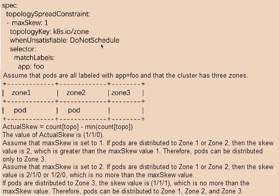
The selector field selects all pods with the app=foo label. The selected pods must be distributed across zones, and maxSkew is set to 1.
The cluster has three zones. Zone 1 has one pod with the app=foo label, so does Zone 2.
The formula for calculating the number of unevenly distributed pods is as follows: ActualSkew = count[topo] - min(count[topo]).
A list of matched pods is fetched based on the selector field.
The matched pods are grouped based on the topologyKey field to obtain count[topo].
See the preceding figure.
Assume that maxSkew is set to 1. If the pods are distributed to Zone 1 or Zone 2, then the skew value is 2, which is greater than the maxSkew value. Therefore, the pods can only be distributed to Zone 3. If the pods are distributed to Zone 3, then min(count[topo]) and count[topo] are equal to 1, and the skew value is 0. Therefore, the pods can only be distributed to Zone 2.
Assume that maxSkew is set to 2. If the pods are distributed to Zone 1 or Zone 2, then the skew value is 2/1/0 or 1/2/0, and the maximum value is 2, which is no more than the value of maxSkew. Therefore, the pods can be distributed to Zone 1, Zone 2, and Zone 3.
EvenPodsSpread ensures the even distribution of pods based on a topology key. If you want to evenly distribute pods to each topology, you can set maxSkew to 1. However, this description is not strictly controlled. For example, topologyValue does not specify the number of topologies to which pods are distributed.
Next, let's take a look at the scoring algorithms, which deal with cluster fragmentation, disaster recovery, resource usage, affinity, and anti-affinity.
Scoring algorithms can be divided into four types:
The following introduces the scoring algorithms related to resource usage.
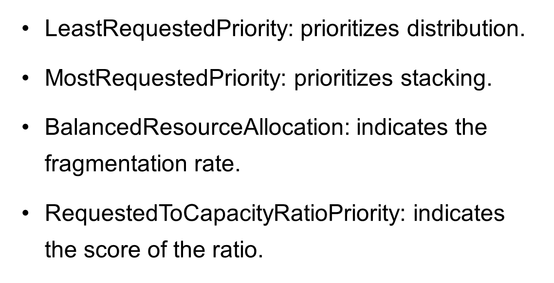
Four node-specific scoring algorithms are related to resource usage, as shown in the preceding figure.
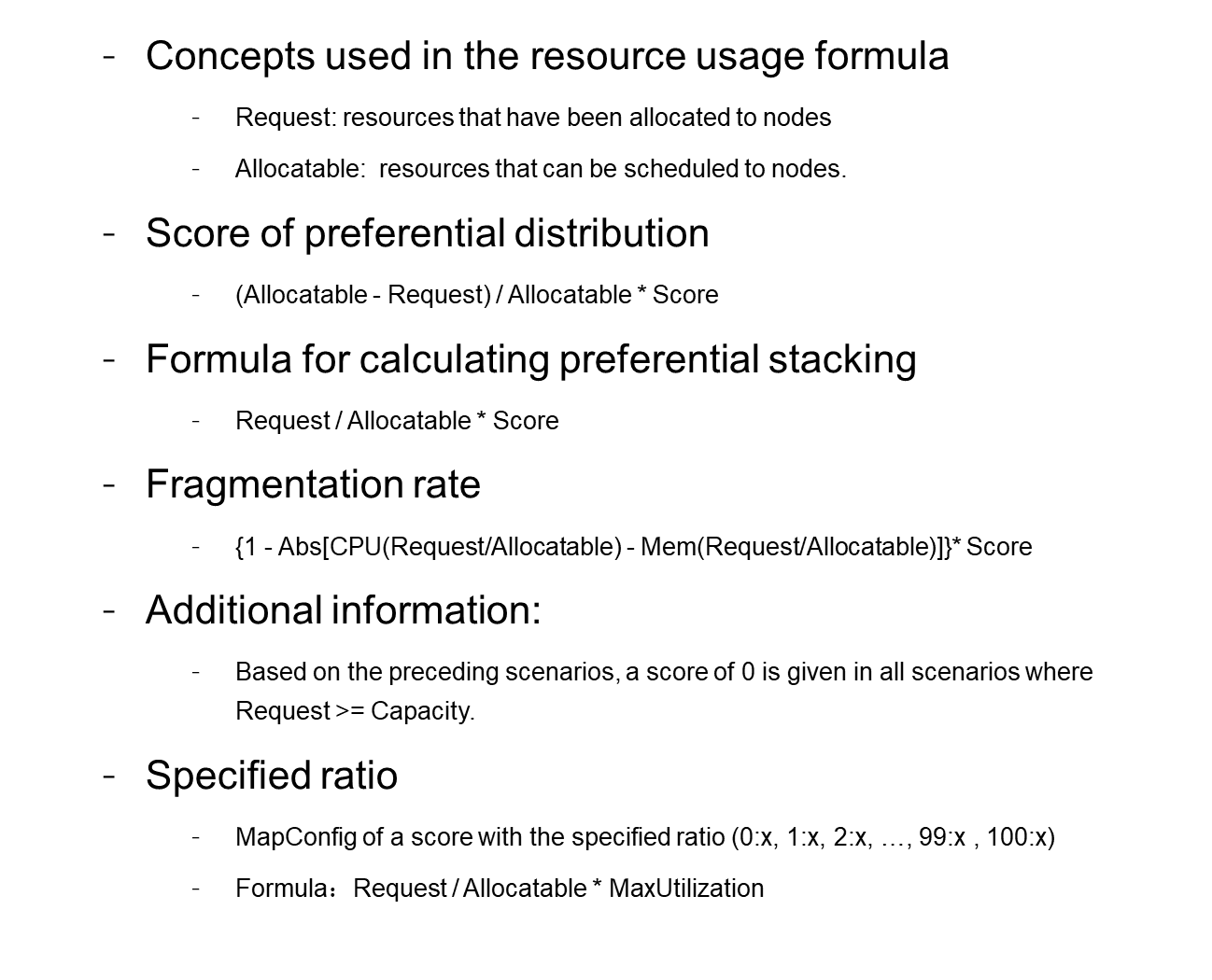
Request indicates the resources that have been allocated to nodes.
Allocatable indicates the resources that can be scheduled to nodes.
Pods are assigned to the node with the highest idle resource rate rather than the node with the most idle resources. Idle resource rate = (Allocatable - Request)/Allocatable. A node with a higher idle resource rate is given a higher score so that pods are preferentially assigned to it. (Allocatable - Request) indicates the number of idle resources on the node after pods are assigned to it.
Pods are assigned to the node with the highest resource usage. Resource usage = Request/Allocatable. A node with a higher resource usage is given a higher score so that pods are preferentially assigned to it.
The fragmentation rate indicates the usage difference among multiple resources on a node. Currently, this feature supports statistics for CPU, memory, and disk resources. If only CPU and memory resources are considered, then the fragmentation rate is calculated as follows: Fragmentation rate = Abs[CPU(Request/Allocatable) - Mem(Request/Allocatable)]. For example, if the CPU allocation rate is 99% and the memory allocation rate is 50%, then the fragmentation rate is equal to 99% - 50% = 50%. The proportion of available CPU resources is 1% and that of available memory resources is 50%. Memory resources are rarely used up by a container. The given score is calculated by subtracting the fragmentation rate from 1. The higher the fragmentation rate, the lower the score.
You can set a score for the usage of each resource when the Kubernetes scheduler is started. In this way, you can control the resource allocation curve for nodes in a cluster.
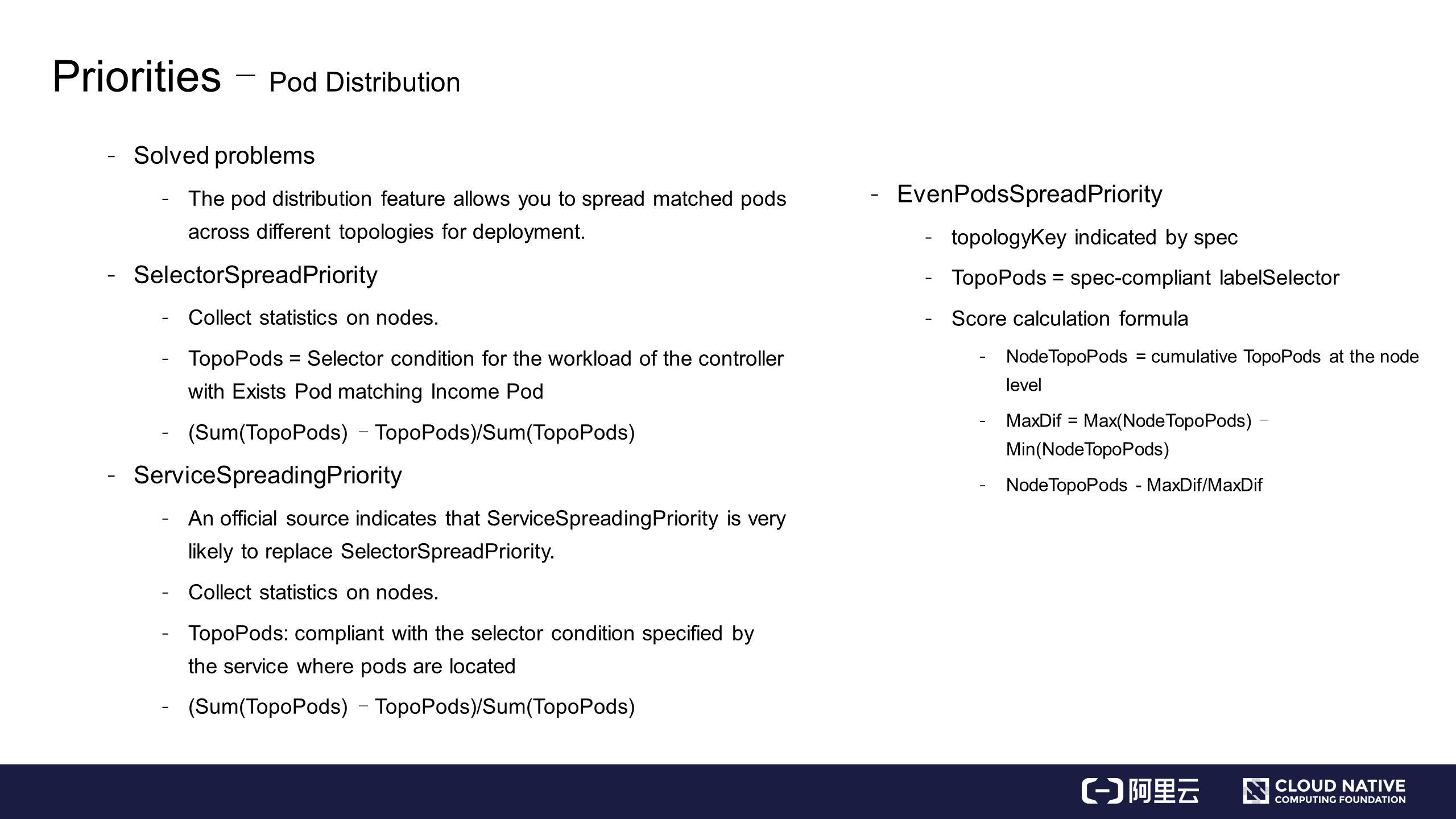
The pod distribution feature allows you to spread matched pods across different topologies during deployment.
SelectorSpreadPriority distributes the pods in a controller across nodes. SelectorSpreadPriority calculates the total number of pods in the controller that manages the pod to be assigned. Assume that the total number of pods in the controller is T. Statistics are collected on these pods based on the nodes where the pods are located. Assume that the statistical value of a node is N. A score given to this node is calculated as follows: (T - N)/T. A higher score indicates that the node has a smaller number of deployed controllers. Then, pods are assigned to nodes based on the node workload.
An official source has indicated that ServiceSpreadingPriority is very likely to replace SelectorSpreadPriority. In my opinion, the reason is that ServiceSpreadingPriority ensures an even allocation of services.
EvenPodsSpreadPriority allows you to specify how to distribute a group of matched pods in a topology as needed.
EvenPodsSpreadPriority is complex due to its constant changes. Assume that there is a topology where pods must be distributed across nodes based on spec. You can use the preceding formula to calculate the number of pods on a node that match labelSelector indicated by spec. Then, calculate the maximum resource usage difference and the pod assignment weight of each node. Pods are preferentially assigned to nodes with higher weights.
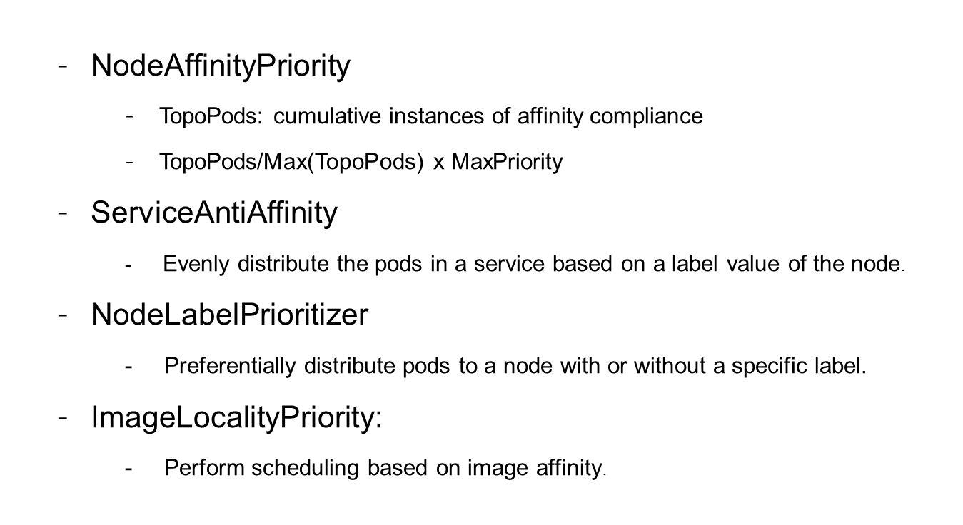
InterPodAffinityPriority
First, let's take a look at the following scenarios:
NodePreferAvoidPodsPriority
NodePreferAvoidPodsPriority prevents the pods managed by certain controllers from being assigned to specific nodes by adding annotations to these nodes. Pods are preferentially assigned to nodes that do not meet the annotation conditions.
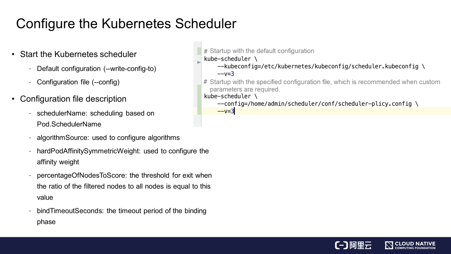
You can start a Kubernetes scheduler in one of the following ways:
If you start the Kubernetes scheduler with the default configuration, you can view the related parameters as follows: Use --write-config-to to write the default configuration to the specified file.
The default configuration file is shown in the following figure.
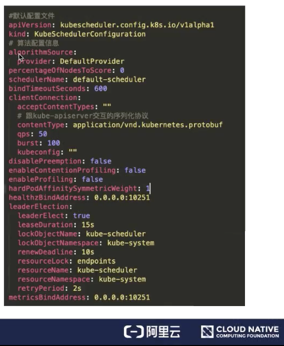

The configuration files of filter algorithms and scoring algorithms can use the following three formats:
The Provider format supports two implementation modes:
ClusterAutoscalerProvider prioritizes stacking, whereas DefaultProvider prioritizes distribution. Use ClusterAutoscalerProvider if you enable automatic scaling for your nodes.
The configuration of the policy file is shown in the following figure.
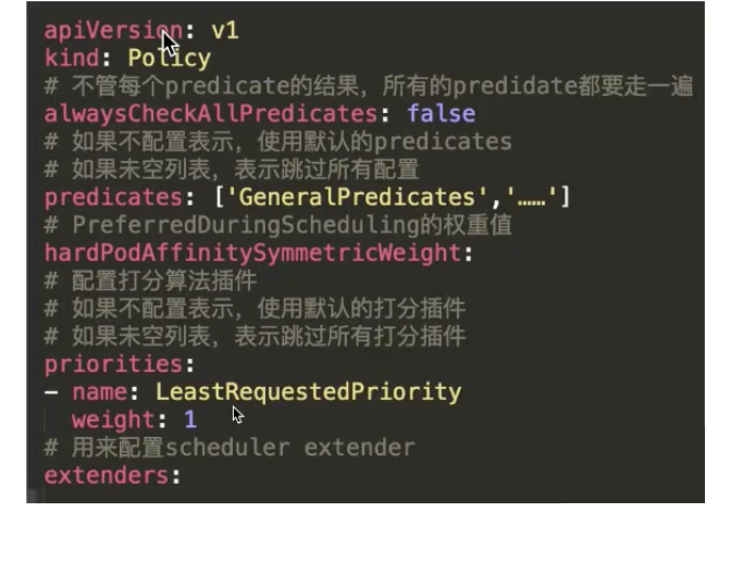
The filtering algorithm is predicates, and the scoring algorithm is priorities. "extenders" is also configured. Pay attention to the alwaysCheckAllPredicates parameter. This parameter indicates whether to continue processing when "false" is returned in the filter list. The default value is false. If it is set to true, all plugins are traversed.
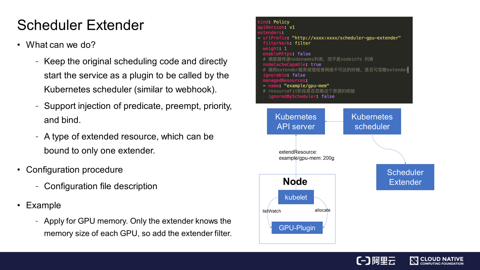
To start, let's take a look at what a scheduler extender can do. You can start a scheduler extender after starting the Kubernetes scheduler.
You can configure the extender in a configuration file, such as the policy file. The configuration items include the extender URL, HTTPS service availability, and node cache availability. If a node cache exists, the Kubernetes scheduler transmits node information only to the nodenames list. If the node cache is disabled, the Kubernetes scheduler passes in the complete structure of nodeinfo.
The ignorable parameter indicates whether the Kubernetes scheduler can ignore the scheduler extender when the network is unreachable or a service error is returned. managedResources indicates that the Kubernetes scheduler uses the scheduler extender when processing the specified resource type. If this parameter is not specified, the Kubernetes scheduler uses the scheduler extender for all resource types.
GPU share is used as an example. The scheduler extender records the size of memory allocated to each GPU. The Kubernetes scheduler checks whether the total memory of GPUs on the nodes is sufficient. The extended resource is example/gpu-men: 200g. Assume that a pod needs to be scheduled. You can view the extended resource through the Kubernetes scheduler. The extended resource is configured by the scheduler extender. In the schedule phase, the scheduler extender is called through the configured URL, allowing the Kubernetes scheduler to implement the GPU share capability.
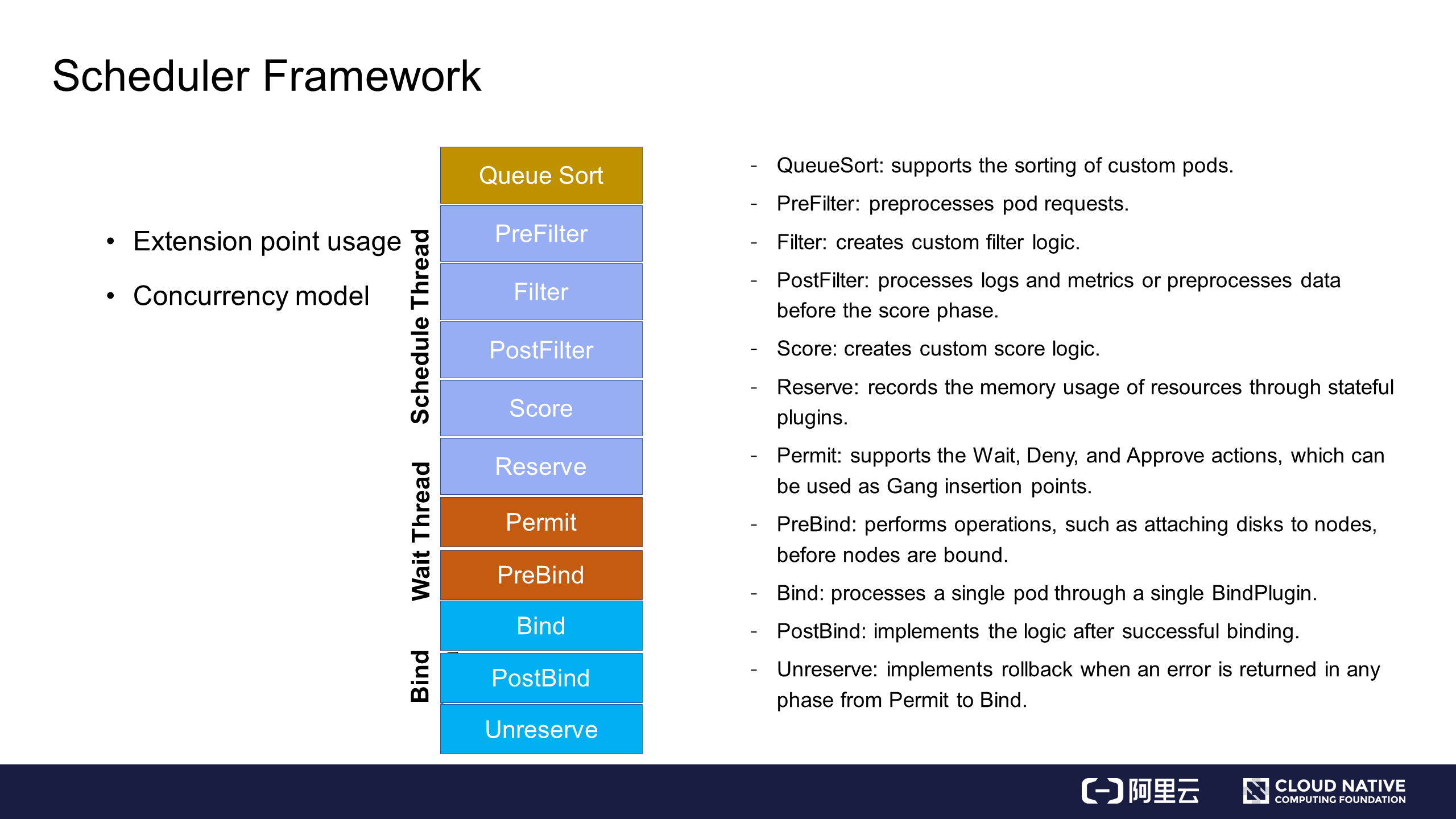
The following describes the usage of extension points and the concurrency model.
Extension points are used in the following ways:
In the concurrency model, the main scheduling process runs from the PreFilter phase to the Reserve phase, as shown in the blue part of the preceding figure. The main scheduling process starts when a pod is fetched from the queue for scheduling and ends when the Reserve phase is complete. Then, the pod is asynchronously transferred to the wait thread. If the wait thread is successfully executed, the pod is transferred to the bind thread. This forms a threading model.
The following explains how to write and register custom plugins.
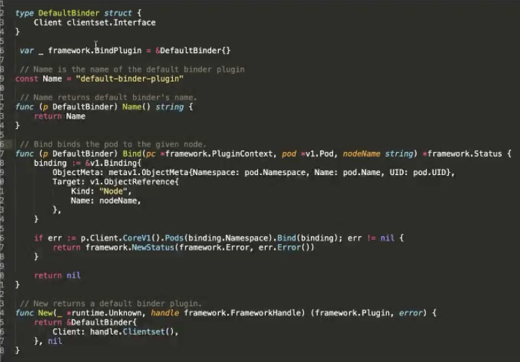
Here, we will use an official example. In the Bind phase, if you want to bind a pod to a specific node, you need to perform the Bind operation on the Kubernetes API server. Two APIs are called. The Bind API declares the scheduler name and the bind logic. Finally, a constructor method is implemented to specify the logic.
Start a scheduler with custom plugins:
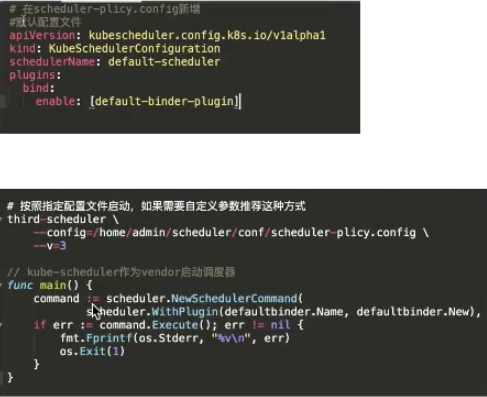
You can use either of the following methods to register the scheduler during startup:
Let's summarize what we have learned in this article.
Getting Started with Kubernetes | Scheduling and Resource Management
Getting Started with Kubernetes | GPU Management and Device Plugin Implementation

480 posts | 48 followers
FollowAlibaba Developer - June 16, 2020
Alibaba Developer - April 3, 2020
Alibaba Developer - June 17, 2020
Alibaba Developer - February 26, 2020
Alibaba Developer - June 17, 2020
Alibaba Developer - March 31, 2020

480 posts | 48 followers
Follow Container Service for Kubernetes
Alibaba Cloud Container Service for Kubernetes is a fully managed cloud container management service that supports native Kubernetes and integrates with other Alibaba Cloud products.
Learn More ACK One
Provides a control plane to allow users to manage Kubernetes clusters that run based on different infrastructure resources
Learn More Cloud-Native Applications Management Solution
Accelerate and secure the development, deployment, and management of containerized applications cost-effectively.
Learn More Container Registry
A secure image hosting platform providing containerized image lifecycle management
Learn MoreMore Posts by Alibaba Cloud Native Community