By Huang Ke (nicknamed Zhitian), Senior R&D Engineer at Alibaba
The storage service must create snapshots for online data and restore data quickly to improve the fault tolerance of data operations in volumes. Snapshots also help to quickly complete data replication and migration operations, such as environment replication and data development. Kubernetes provides a CSI Snapshot controller to create volume snapshots.
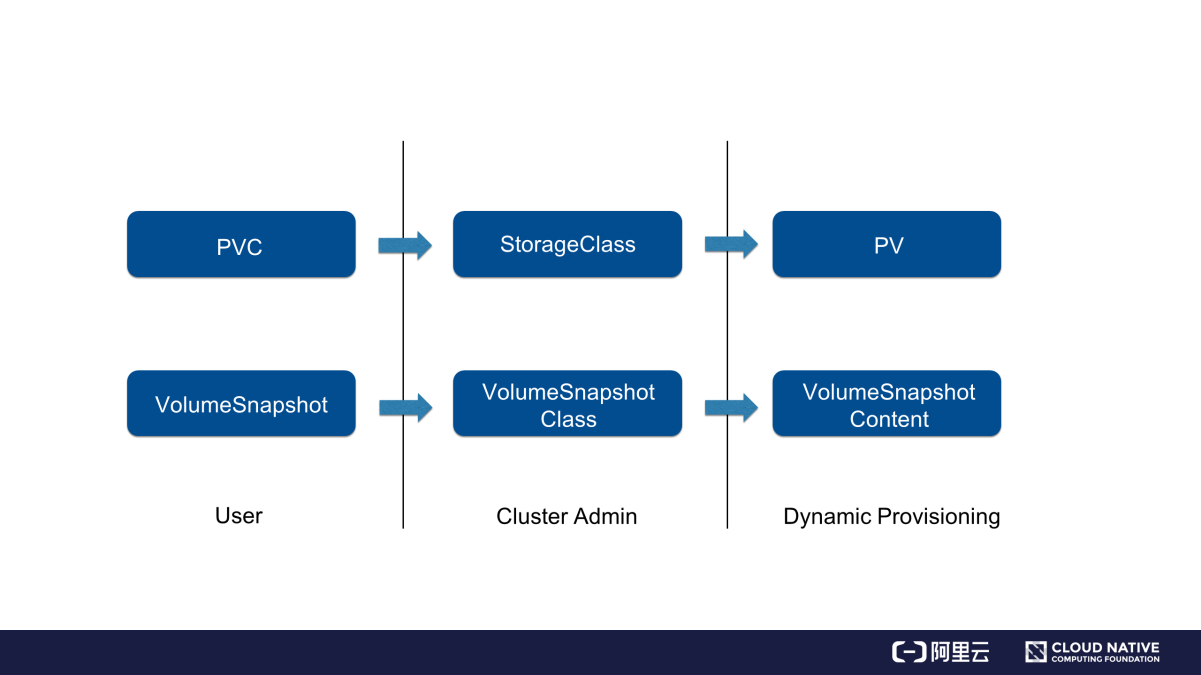
Kubernetes uses a system of persistent volume claim (PVC) and persistent volume (PV) to simplify storage operations. The volume snapshot design follows the PVC and PV system design. To create a volume snapshot, create a VolumeSnapshot object and specify the VolumeSnapshotClass object. Then, the relevant component in a cluster dynamically creates the volume snapshot and the corresponding VolumeSnapshotContent object. As shown in the following figure, the VolumeSnapshotContent object is dynamically created following a process similar to the dynamic PV provisioning process.
How to quickly restore data from a volume snapshot? The following figure provides the answer.
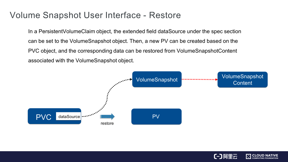
As shown in the preceding figure, specify the VolumeSnapshot object in the dataSource field of the PVC object. After the PVC is committed, the relevant component in the cluster finds the data of the volume snapshot that is specified by the DataSource field, creates the matching volume and PV object, and then restores the data of the volume snapshot in the new PV.
"Topology" in this article refers to the locations of nodes in a Kubernetes cluster. Specify the topology where a node is located in its labels field.
There are three types of commonly used topology fields:
failure-domain.beta.kubernetes.io/region. This label identifies the regions in which the nodes in an inter-region Kubernetes cluster reside.failure-domain.beta.kubernetes.io/zone. This label identifies which zones wherein the nodes in an inter-zone Kubernetes cluster reside.kubernetes.io/hostname. This label will be described in detail in the section about local PVs at the end of the article.Apart from these commonly used topology fields, define custom topology fields. Use a string to identify a topology. The values of this key identify different locations in the topology.
For example, the rack field is used to identify each rack in a data center as a topology. This field identifies locations of hosts according to the racks on which they are located. For hosts on rack 1, add a rack label and set its value to rack1, such as rack=rack1. Similarly, set the label of hosts on rack 2 to rack=rack2. In this way, identify the racks where nodes in a Kubernetes cluster are located.
The following section describes how topologies are used in Kubernetes.
As mentioned in the previous session, Kubernetes uses a PV and PVC system to separate storage resources from computing resources. If a PV restricts the data query locations, set the nodeAffinity field to specify which nodes query data in this PV.
Why does a PV need to restrict the data query locations? The reason is that the pod creation and PV provisioning processes are performed concurrently in a Kubernetes cluster. Therefore, Kubernetes cannot ensure whether the node to which the pod is finally scheduled queries data from the volume matching the PV with query location restrictions. As a result, the pod doesn't run properly. The following describes two typical cases:
First, let's look at an example of local PV. A local PV is a logical encapsulation of a local volume on a node. Data in the local volume is queried through the local PV. Why are local PVs required? In simple words, the PV or PVC system was intended for distributed storage at the beginning. Distributed storage depends on network connections, and therefore may not provide as high an I/O performance as required by certain business applications. Such applications need to query data from local storage to achieve a higher I/O performance without network overheads. However, using local storage also brings disadvantages. Distributed storage guarantees high availability with multiple replicas, whereas local storage requires business applications to guarantee the high availability themselves by using Raft or a similar protocol.
Then, what would happen if a local PV does not restrict the data query locations?
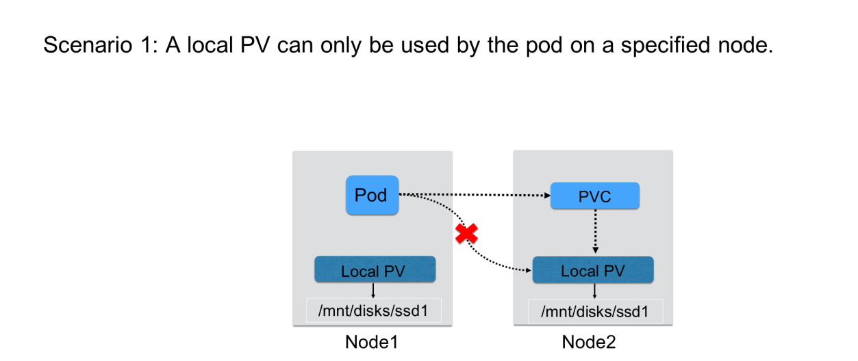
After a PVC is committed, the Kubernetes PV controller may bind it to the PV on node 2. However, the pod that uses this PV may be scheduled for node 1. As a result, the pod cannot use the volume on node 2 after startup.
The following figure shows another problem that may arise if a PV does not restrict the data query locations.
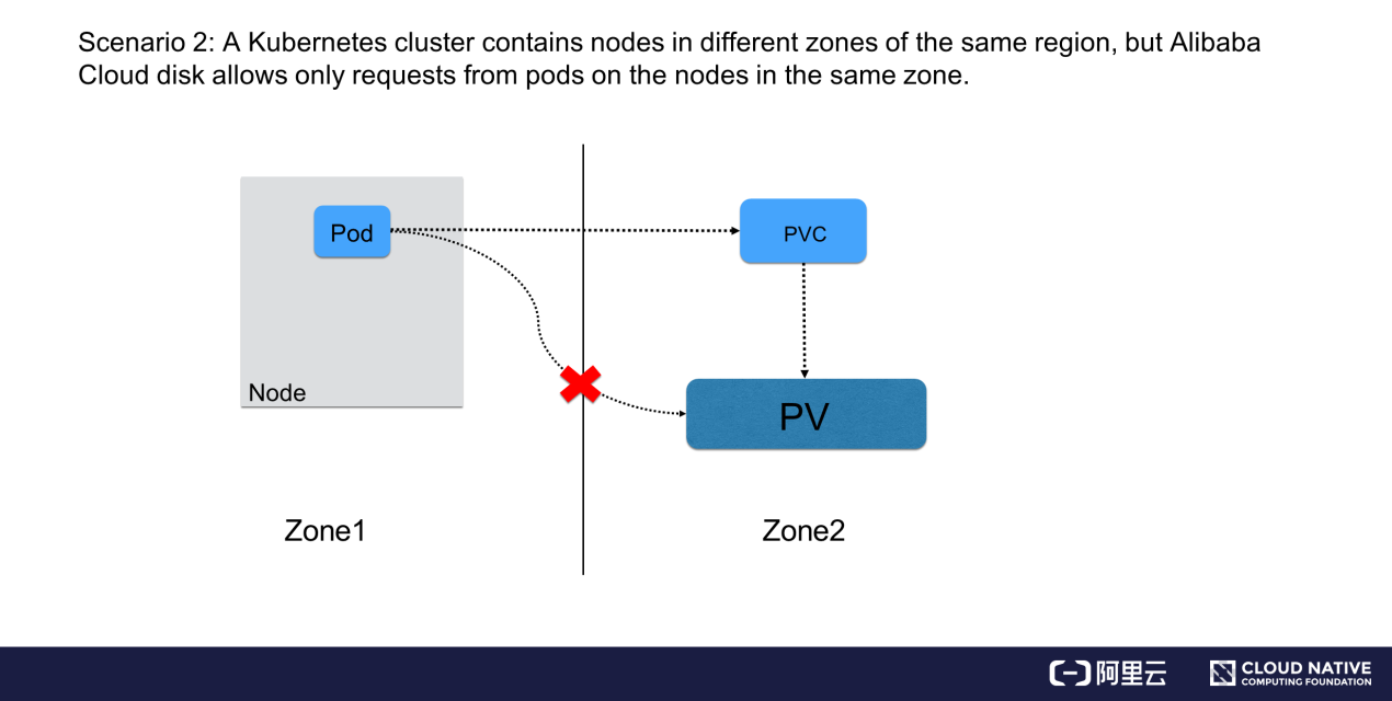
A Kubernetes cluster contains nodes distributed in multiple zones of the same region. A dynamically created volume is in zone 2, but the pod that is committed later and needs to use this volume may be scheduled to zone 1. In this case, the pod cannot use the volume. Block storage services such as Alibaba Cloud disks do not support data querying across zones. If a volume is in zone 2 but the pod runs in zone 1, the pod cannot use the volume.
Now, let's see how Kubernetes uses the volume topology-aware scheduling capability to solve both problems.
To conclude, the preceding problems occur because the pod that needs to use a PV is scheduled to a different node after the PV controller binds the PVC to this PV or dynamically creates the PV. However, a PV imposes restrictions on the nodes where the pod is located. Take a local PV as an example. A pod uses this PV only if it is scheduled to the specified node. In scenarios involving inter-zone data querying, the pod that needs to use the PV queries data from an Alibaba Cloud disk only if the disk is scheduled to a node in the same zone as the PV. Therefore, how does Kubernetes solve both problems?
Simply put, Kubernetes delays PV-PVC binding and dynamic PV provisioning until the pod is scheduled to a specific node. What is the benefit of this implementation?
To delay PV-PVC binding and PV provisioning, three Kubernetes components need to be modified:
Thus far, we have covered the basics of volume topology-aware scheduling.
Next, let's demonstrate the basics introduced in section 1 by using several YAML samples.
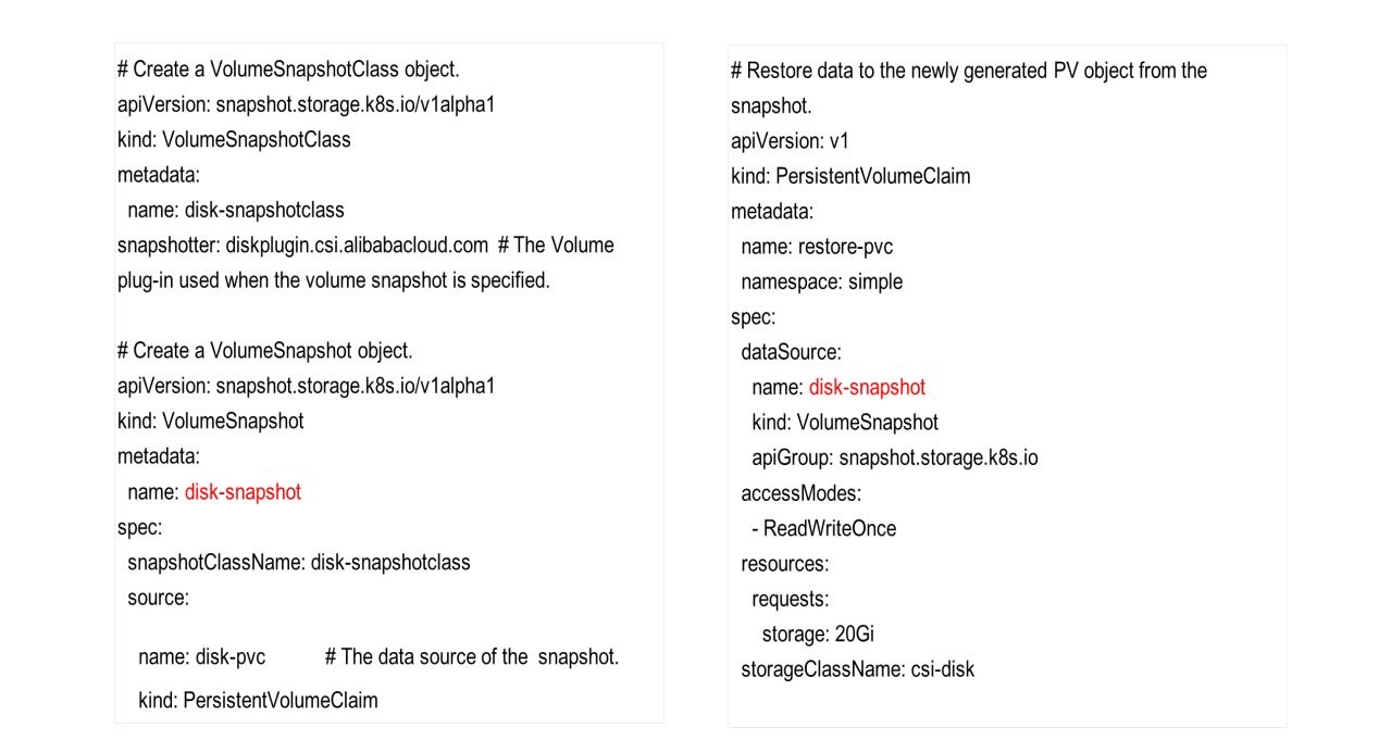
To create a volume snapshot, first, the cluster administrator creates a VolumeSnapshotClass object in the cluster. This object has an important field named Snapshot, which specifies the volume plug-in that is used to create a volume snapshot. The volume plug-in is deployed in advance and will be described in detail later in this article.
Then, the user who wants to create a volume snapshot declares the VolumeSnapshotClass object by specifying its name and source. Source is an important field that identifies the data source of the snapshot. In this example, the object name is set to disk-pvc, which indicates that this PVC object will be used to create the volume snapshot. After the VolumeSnapshot object is committed, the relevant component in the cluster finds the PV that matches the PVC and creates a snapshot of the PV.
Now, to restore data from this volume snapshot, declare a new PVC object and specify the volume snapshot in the DataSource field under the spec section. In this example, the data source is disk-snapshot. After this PVC is committed, the relevant component in the cluster dynamically creates a PV. Data in this PV is from the volume snapshot that was created earlier.
The following figure shows a YAML sample of a local PV.
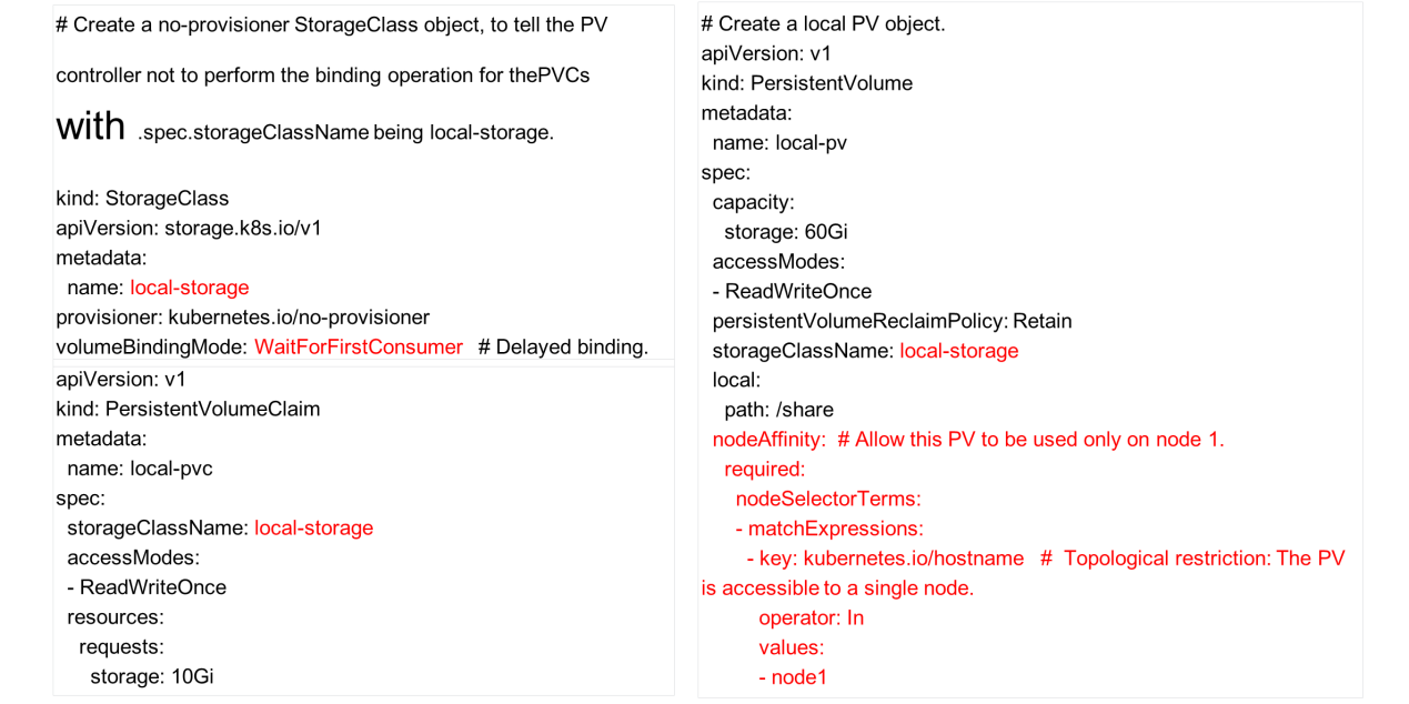
In most cases, local PVs are created statically and hence, the PV object is declared first. Since a local PV allows only requests from the local node, this restriction must be implemented by using the nodeAffinity field of the PV object. As shown in the preceding figure, the key of the topology is set to kubernetes.io/hostname, which specifies that the PV is accessible only from node 1. Thus, the pod that needs to use this PV must be scheduled to node 1.
Why do we need to specify the StorageClassName field for the statically created PV? As mentioned earlier, the binding operation must be delayed for the local PV to work properly. Therefore, the PV controller does not bind the PVC to a PV immediately after the PVC is committed, even though a matching PV is available in the cluster. Instead, the PV controller needs to be informed somehow of the conditions in which the binding operation needs to be delayed. The StorageClass object is used to inform the PV controller. Note that the provisioner field of the StorageClass object is set to no-provisioner, which is to inform Kubernetes that the PV will not be dynamically created. The VolumeBindingMode field is set to WaitForFirstConsumer, which means the binding is delayed.
When the PV controller detects the PVC that is committed by the user, it finds the StorageClass object of the PVC and knows that the binding mode is delayed binding. Therefore, it does not perform any operations.
After the pod that needs to use the PVC is scheduled to a node that matches the nodeAffinity attribute of the PV, the PV controller binds the PVC to the PV. This ensures that the pod uses this local PV. This example shows how the topological restriction of a PV is met in a static PV provisioning scenario.
The following example shows how the topological restriction is implemented in a dynamic PV provisioning scenario.
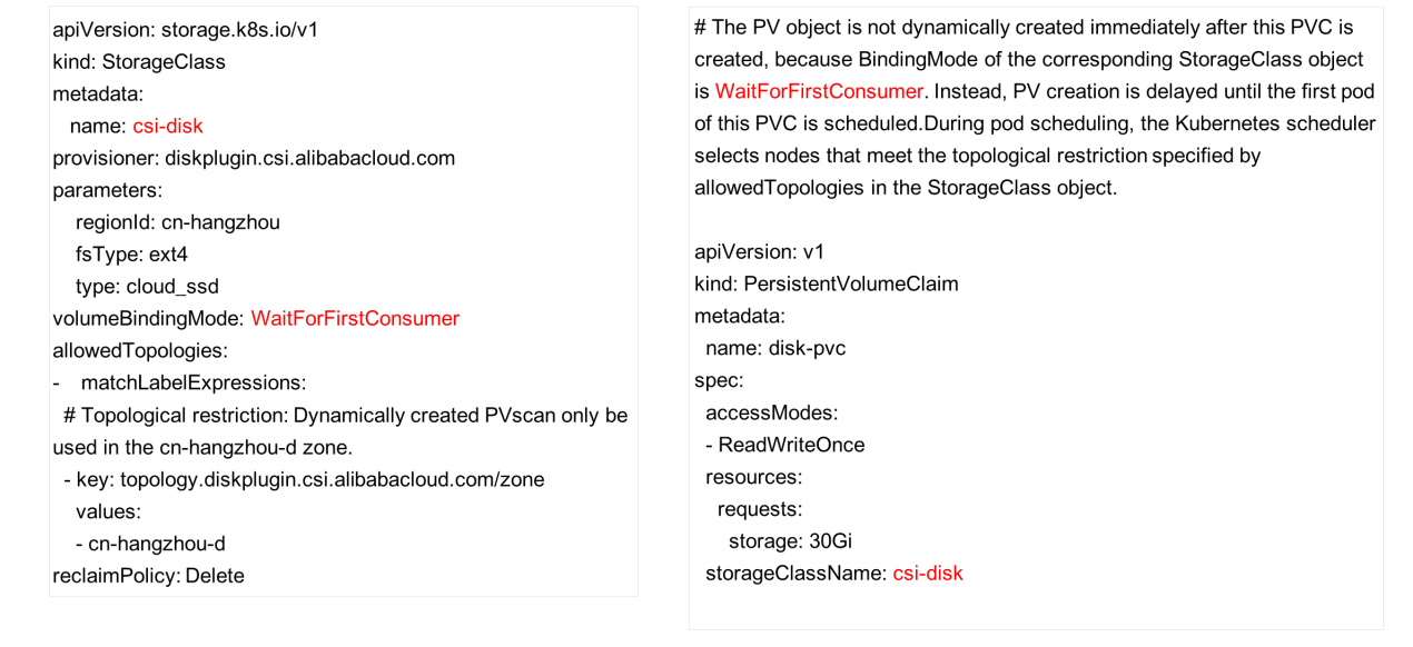
How to specify the topological restriction for a dynamically created PV?
First, set the VolumeBindingMode field of the StorageClass object to WaitForFirstConsumer.
Another important field that must be set is allowedTopologies, which specifies the topological restriction. The preceding figure shows that a zone is specified, which implies the following:
1) The dynamically created PV must be accessible from this zone.
2) The binding operation is delayed. When the scheduler finds that the committed PVC matches the StorageClass object, it selects nodes for the pod from this zone.
In summary, it is critical to ensure that the dynamically created PV is accessible from the specified zone and that the scheduler schedules the pod to a node in the same topology as the PV. The PVC file is written in the same way as before, except setting the topological restriction in the StorageClass object.
This section demonstrates the preceding operations in a live environment.
The following figure shows the Kubernetes cluster that was built on Alibaba Cloud server. The cluster consists of three nodes: one master node and two common nodes. No pod is scheduled for the master node.

Deploy the required plug-ins, including a snapshot plug-in (csi-external-snapshot*) and a dynamic cloud disk plug-in (csi-disk*).

Now, let's see how to create a volume snapshot. First, dynamically create a disk.
To create the disk, create a StorageClass object, then create a PV based on the PVC, and finally create a pod that will use the PV.

Now, create the snapshot. The first configuration file required is snapshotclass.yaml.

The configuration file specifies the plug-in that is used to create the snapshot. This plug-in is csi-external-snapshot-0.

Next, create a volume-snapshotclass file. After the creation is completed, create the snapshot.

In the snapshot.yaml file, the VolumeSnapshot object is specified to create a volume snapshot, and the PVC that has been created is specified as the data source of the snapshot. Execute the file to create the snapshot.
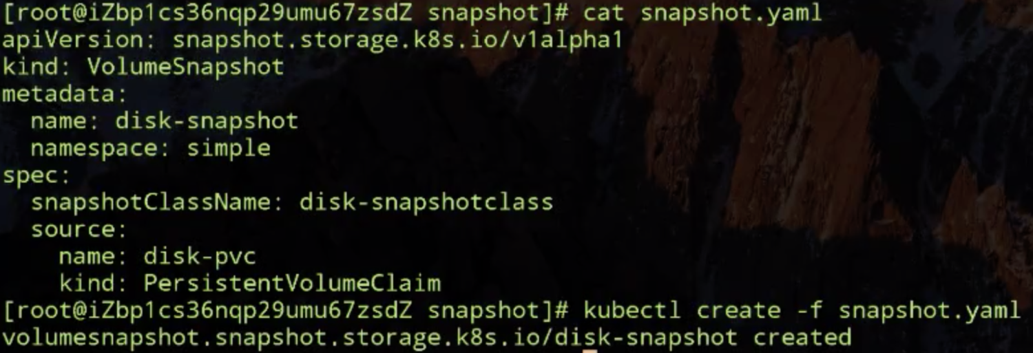
Check whether the snapshot is created. The following figure shows that the snapshot content was created 11 seconds ago.

Check the information shown in the following figure, particularly the VolumeSnapshotContent field. This field records the snapshot ID after creating the snapshot. The matching PV may be found based on the PVC.
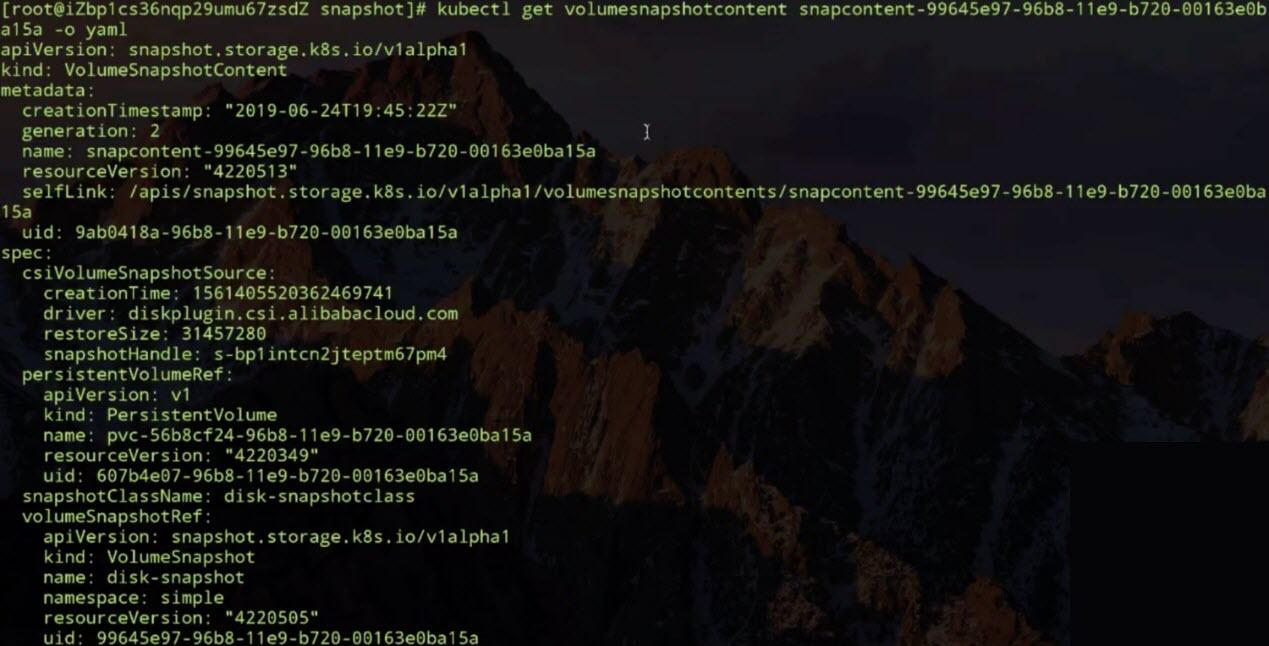
The preceding snippet shows the is the exact general procedure for creating a snapshot. Next, delete the snapshot by using the VolumeSnapshot object. Note that the dynamically created VolumeSnapshotContent object is also deleted.

Now, let's see how to create a dynamic PV and set the topological restriction. First, create a StorageClass object, and then set the restriction in the object. Set the volumeBindingMode field to WaitForFirstConsumer to delay the binding operation, and then set the topological restriction. This demonstration specifies a zone in the allowedTopologies field.
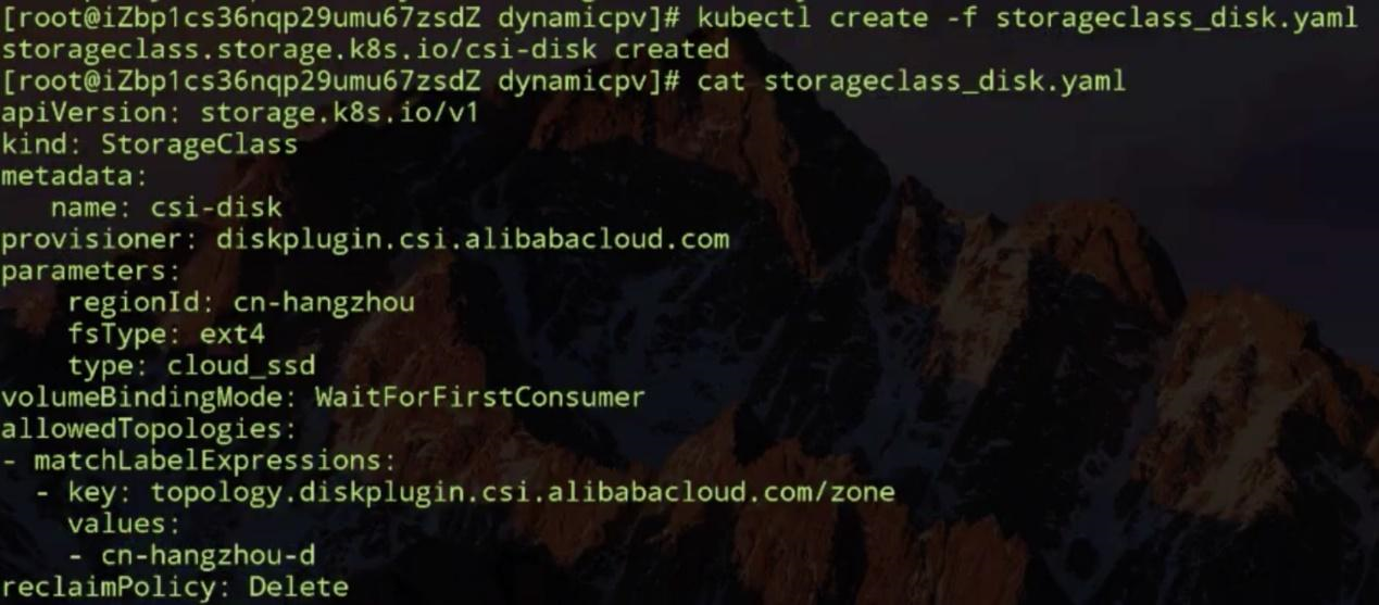
Then, create a PVC. Theoretically, a PVC is in the pending state after its creation. The binding operation is delayed until the pod scheduling is complete, and no pod is available now. Therefore, the PVC cannot be bound to any PV and no PVs can be created dynamically.

Let's create a pod that uses this PVC and see what will happen. Note that the pod is also in a pending state.
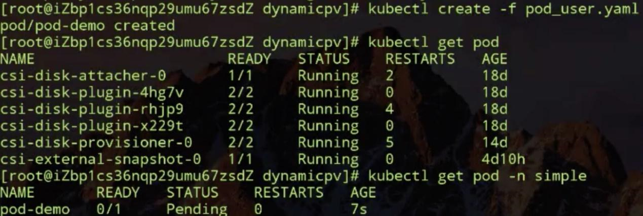
The pod is pending because of a scheduling failure. Note the reason for the scheduling failure: One node (the master node) has taints, and the other two nodes have no PVs available for binding.

Why do both nodes have no PVs? Why no PV is created dynamically?
Let's check the topological restriction in the StorageClass object. As mentioned earlier, the PV that is created through this StorageClass object must be accessible from the cn-hangzhou-d zone, and the pod that uses this PV must be scheduled to a node in this zone.
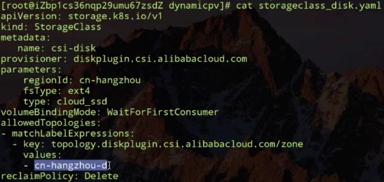
Check whether the nodes have this type of topology information.
First, view all information about the first node and check whether the labels field contains a topology key to specify the zone. This node has a topology key, but the key specifies the cn-hangzhou-b zone rather than cn-hangzhou-d specified in the StorageClass object.
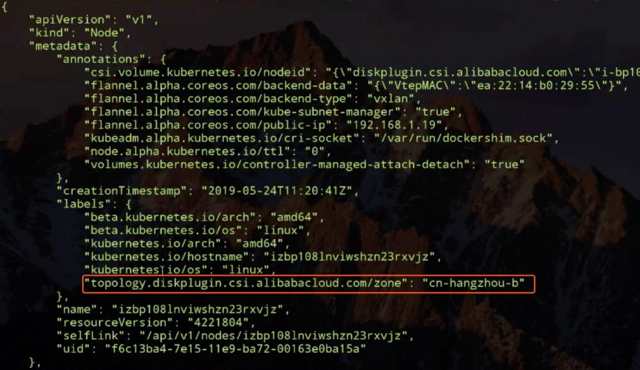
The topology key of the other node also specifies the cn-hangzhou-b zone.
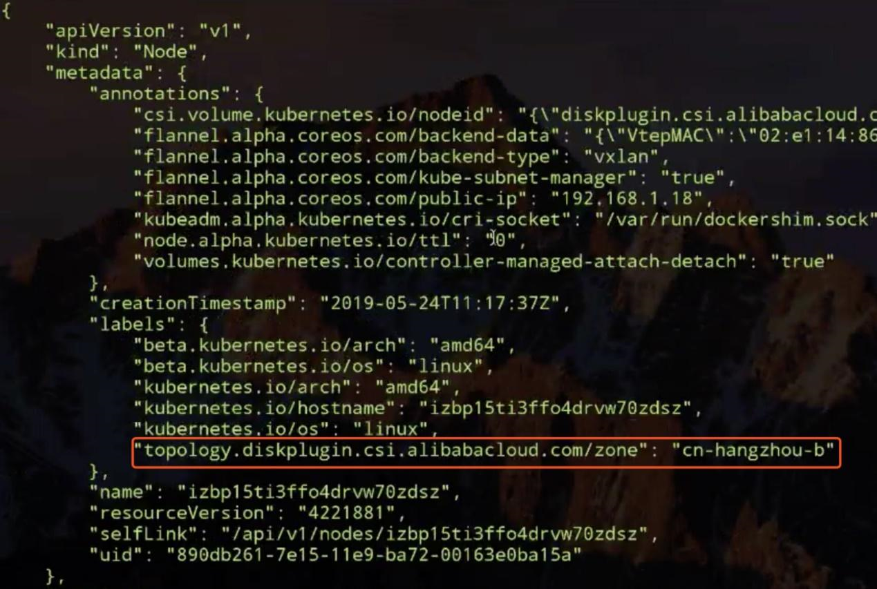
As a result, the pod fails to be scheduled for either of both nodes. Now, change the zone in the StorageClass object from cn-hangzhou-d to cn-hangzhou-b.
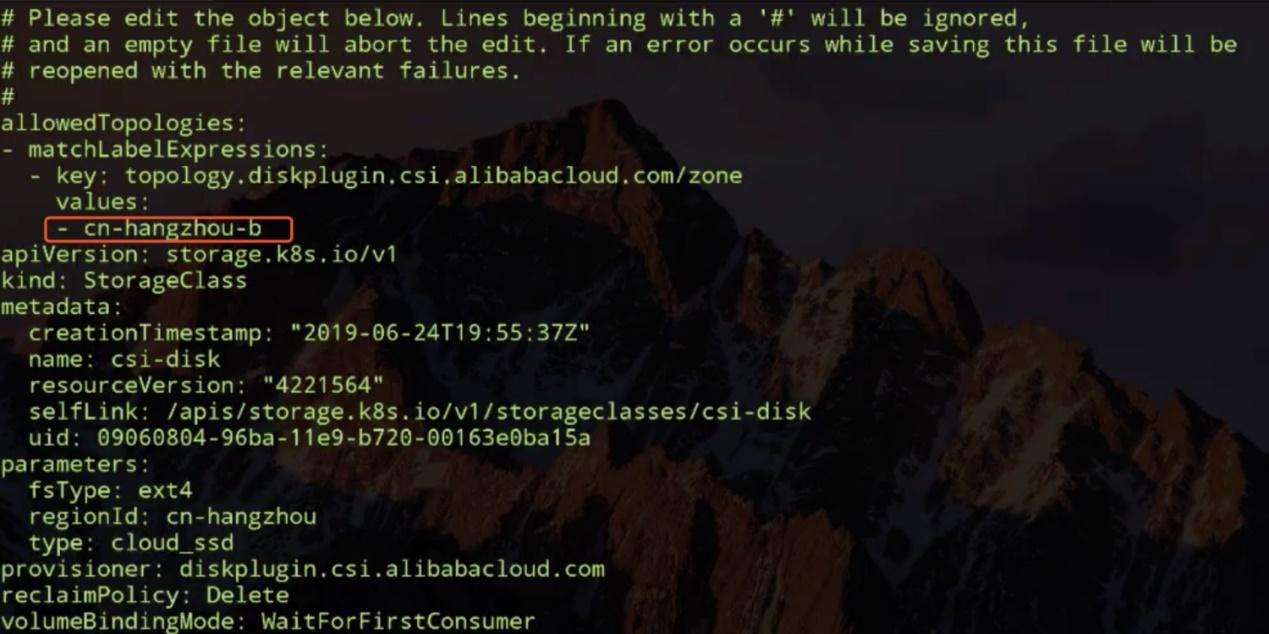
The modified topological restriction requires that the dynamically created PV is accessible from the cn-hangzhou-b zone, so that the pod that uses the PV schedules to a node in this zone. Then, delete the previous pod to trigger the scheduling again. Note that the scheduling has succeeded and the pod is in the container startup stage.
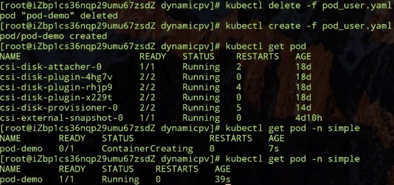
This indicates that the topology of both nodes in the cluster meets the requirement of the StorageClass object once the zone is changed from cn-hangzhou-d to cn-hangzhou-b. In this case, the pod can be scheduled to a node. From the last line in the preceding figure, observe that the pod is in running state, which indicates that the pod works properly after the topological restriction change.
Let's take a look at the volume snapshot and topology-aware scheduling process in Kubernetes.
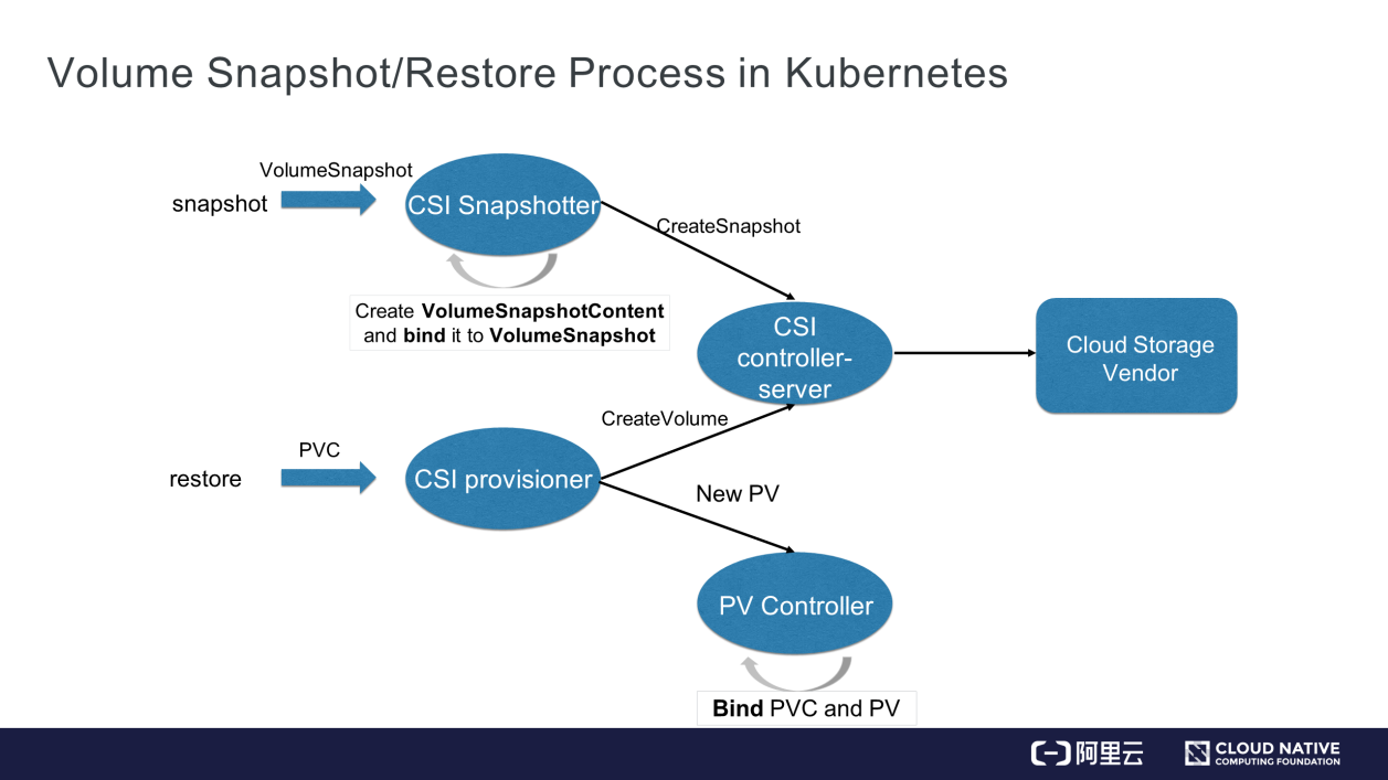
First, let's look at the CSI-related steps in the volume snapshot creation process. We recommend using out-of-tree CSI plug-ins to extend the storage in Kubernetes.
Storage extension is implemented in two parts:
Both parts are interconnected with UNIX domain sockets. Both parts are indispensable for storage extension.
As shown in the preceding figure, the VolumeSnapshot object is detected by the CSI Snapshotter controller after it is committed. The CSI Snapshotter controller then calls the CSI plug-in through GPPC. The CSI plug-in uses the corresponding API to create the volume snapshot and sends it to the CSI Snapshotter controller. The CSI Snapshotter controller then stores the snapshot information in the VolumeSnapshotContent object and binds the content to the VolumeSnapshot object that is committed by the user. This binding operation is similar to PV-PVC binding.
Then, how can the previous data from the volume snapshot be restored? As mentioned previously, we can create a PVC object and specify the snapshot in its dataSource field. When the PVC is committed, it is detected by the CSI provisioner, which then creates a volume through Google Remote Procedure Call (GRPC). This process differs from the preceding process in that a snapshot ID is specified for the CSI provisioner. When a volume is created on a host of the cloud storage vendor, the data of the volume snapshot is restored in this new volume. Then, the CSI provisioner adds information about the new volume in a new PV object. When the PV controller detects the new PV object, it binds the PVC that is committed by the user to the PV, so that the pod queries the restored data through the PVC. Kubernetes follows this process to handle volume snapshot requests.
The following describes the volume topology-aware scheduling process:
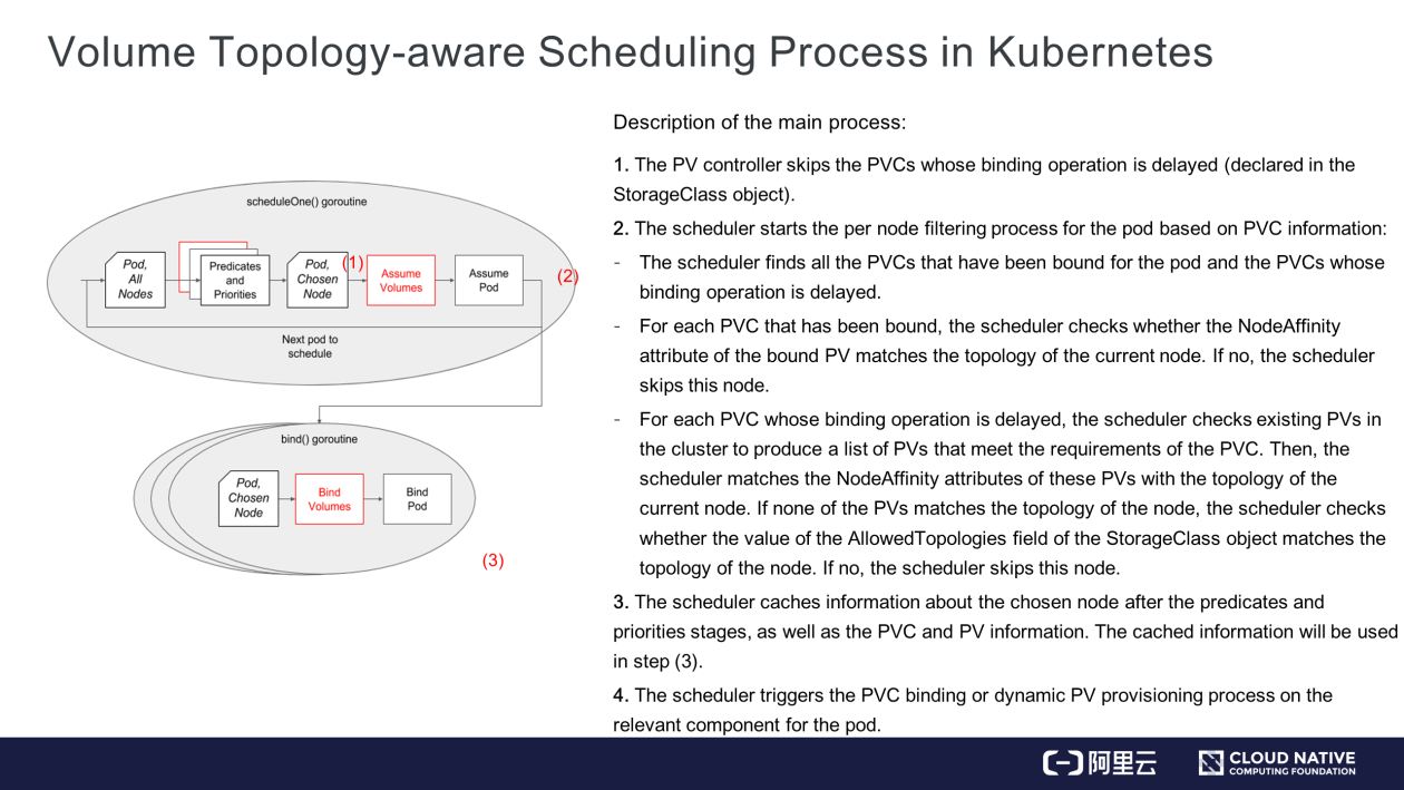
Step 1) Declare the delayed binding mode. This binding mode is specified in the StorageClass object. The relevant operation has been explained earlier and will not be repeated here.
Step 2) The red boxes in the preceding figure highlight the new volume topology-aware scheduling logics added to the scheduler. In the condition without these new logics, the scheduler follows the below process to select a node for a pod:
However, it is critical to understand how nodes are selected in step 2 after the volume-related scheduling logics are added.
After the preceding steps are completed, the scheduler finds all the nodes that meet the pod's requirements for computing and storage resources.
Step 3) It's actually an optimization process in the scheduler. In simple terms, the scheduler updates information about the node chosen for the pod after the predicates and priorities stages, as well as PV and PVC information that is cached in the scheduler.
Step 4) In this step, the pod is scheduled to the chosen node, and the PVC that will be used by the pod needs to be bound to an existing PV or a dynamically created PV. The scheduler updates related information in the PVC and PV objects, and then triggers PV-PVC binding on the PV controller or dynamic PV provisioning on the CSI provisioner.
This article explains the Kubernetes resource objects for the volume snapshot feature and how to use these objects in the PVC and PV system. It demonstrates two example problems that occur in actual business scenarios to explain the necessity of volume topology-aware scheduling, and how Kubernetes uses this feature to solve these problems. It further describes the mechanisms of volume snapshot and topology-aware scheduling in Kubernetes in detail to help users get in-depth insights into the implementation of the feature.
Get to Know Kubernetes | Application Storage and Persistent Volumes: Core Knowledge
Getting Started with Kubernetes | Observability: Are Your Applications Healthy?

634 posts | 55 followers
FollowAlibaba Developer - June 17, 2020
OpenAnolis - February 10, 2023
Alibaba Developer - March 31, 2020
Alibaba Developer - September 17, 2021
Alibaba Cloud Native - May 23, 2022
Alibaba Developer - April 2, 2020

634 posts | 55 followers
Follow Container Service for Kubernetes
Alibaba Cloud Container Service for Kubernetes is a fully managed cloud container management service that supports native Kubernetes and integrates with other Alibaba Cloud products.
Learn More ACK One
Provides a control plane to allow users to manage Kubernetes clusters that run based on different infrastructure resources
Learn More Cloud-Native Applications Management Solution
Accelerate and secure the development, deployment, and management of containerized applications cost-effectively.
Learn More Container Registry
A secure image hosting platform providing containerized image lifecycle management
Learn MoreMore Posts by Alibaba Cloud Native Community