To ensure business continuity and high availability, ApsaraDB RDS for PostgreSQL provides the disaster recovery (DR) feature. You can create ApsaraDB RDS for PostgreSQL instances across regions to implement geo-disaster recovery. The RDS instance that is used to implement DR is referred to as a DR instance. This topic describes how to use the disaster recovery feature to implement geo-disaster recovery between RDS instances.
Prerequisites
A DR instance that meets the required requirements is created. For more information, see Create an ApsaraDB RDS for PostgreSQL instance.
The major engine version of the DR instance is the same as that of the source RDS instance.
The DR instance is a primary instance. You cannot use read-only RDS instances as DR instances.
The billing method of the DR instance is pay-as-you-go or subscription. You cannot use serverless instances as DR instances.
The DR instance is empty. The available storage of the DR instance is greater than or equal to the size of the data in the source RDS instance.
A synchronization account for DR is created in the source RDS instance. For more information, see Prepare to create a DR instance.
Step 1: Establish connections
Use Cloud Enterprise Network (CEN) to connect the VPCs of the source RDS instance and the DR instance. For more information, see What is CEN?
In this topic, the source RDS instance and the DR instance are created within the same Alibaba Cloud account and reside in different regions. If the source RDS instance and the DR instance are created by using different Alibaba Cloud accounts, you can connect the VPCs of the instances based on the instructions provided in Connect VPCs in different accounts.
Log on to the CEN console.
On the Instances page, click Create CEN Instance.
In the Create CEN Instance dialog box, click the Create CEN Only tab. Then, configure the following parameters and click OK to create a CEN instance.
NoteYou can also click the Create Scenario-specific CEN (Recommended) tab and create a CEN instance as prompted.
Parameter
Description
Name
Enter a name for the CEN instance.
Description
Enter a description for the CEN instance.
Resource Group
Select a resource group for the CEN instance.
If you do not select a resource group, the CEN instance is added to the default resource group.
You can manage CEN resources and resource groups in the Resource Management console. For more information, see What is Resource Management?
Tag
Add a tag to the CEN instance.
Tag Key: The tag key cannot be an empty string. The tag key can be up to 64 characters in length. The key cannot start with
aliyunoracs:or containhttp://orhttps://.Tag Value: The tag value can be an empty string. The tag value can be up to 128 characters in length. The tag value cannot start with
aliyunoracs:or containhttp://orhttps://.
You can add one or more tags to a CEN instance. For more information about tags, see Manage tags.
On the Instances page, click the ID of the CEN instance that you want to manage.
On the Basic Information tab, click the
 icon next to VPC to add the VPCs of the source RDS instance and the DR instance to the CEN instance.
On the Connection with Peer Network Instance page, configure the following parameters for the source RDS instance.
Parameter
Description
Instance Type
Select Virtual Private Cloud (VPC).
Region
Select the region in which the source RDS instance resides. In this example, China (Beijing) is selected.
Network Instance
Select the VPC ID of the source RDS instance.
You can view the VPC ID on the Database Connection page of the source RDS instance.
VSwitch
Select the vSwitch ID of the source RDS instance and the vSwitch ID in at least one other zone to implement multi-zone disaster recovery.
You can view the vSwitch ID on the Database Connection page of the source RDS instance.
Click OK.
Click Create More Connections and repeat the preceding steps to configure the required parameters for the DR instance.
On the details page of the CEN instance, choose and click Purchase Bandwidth Plan (Subscription).
On the page that appears, configure the following parameters and click Buy Now. Then, complete the payment.
Parameter
Description
CEN ID
Select the CEN instance for which you want to purchase a bandwidth plan.
After you complete the payment, the bandwidth plan is automatically associated with the CEN instance.
Area A
Select one of the areas in which you want to enable inter-region connections.
In this example, Mainland China is selected.
NoteYou cannot change the area after the bandwidth plan is purchased.
For more information about the regions and areas that support bandwidth plans, see Work with a bandwidth plan.
Area B
Select one of the areas in which you want to enable inter-region connections.
In this example, Mainland China is selected.
Billing Method
Select a billing method for the bandwidth plan. Retain the default value Pay-By-Bandwidth.
For more information about bandwidth plan billing, see Billing rules.
Bandwidth
Select a bandwidth value based on your business requirements. Unit: Mbit/s.
Bandwidth Plan Name
Enter a name for the bandwidth plan.
Order time
Select a subscription duration for the bandwidth plan.
You can select Auto-renewal to enable auto-renewal for the bandwidth plan.
Go to the tab and click Allocate Bandwidth for Inter-region Communication.
On the Connection with Peer Network Instance page, configure the following parameters and click OK.
Parameter
Description
Instance Type
Select Inter-region Connection.
Region
Select the region that you want to connect. In this example, China (Beijing) is selected.
Transit Router
The ID of the transit router in the selected region is automatically displayed.
Attachment Name
Enter a name for the inter-region connection.
Peer Region
Select the peer region that you want to connect. In this example, China (Hangzhou) is selected.
Transit Router
The ID of the transit router in the selected region is automatically displayed.
Bandwidth Allocation Mode
Select a bandwidth allocation mode for the inter-region connection. In this example, Allocate from Bandwidth Plan is selected.
Allocate from Bandwidth Plan: Bandwidth is allocated from a bandwidth plan.
Pay-By-Data-Transfer: You are charged for data transfer over the inter-region connection.
Bandwidth Plan
Select a bandwidth plan that is associated with the CEN instance.
Bandwidth
Specify a bandwidth value for the inter-region connection. Unit: Mbit/s.
Default Line Type
Use the default value.
Advanced Settings
Use the default settings. All advanced features are enabled.
Associate with Default Route Table of Transit Router
After this feature is enabled, the inter-region connection is automatically associated with the default route tables of the transit routers in the connected regions to establish associated forwarding correlations. The transit routers use the default route tables to forward network traffic across regions.
Propagate System Routes to Default Route Table of Transit Router
After this feature is enabled, the inter-region connection is associated with the default route tables of the transit routers in the connected regions to establish route learning correlations.
Automatically Advertise Routes to Peer Region
After this feature is enabled, the routes in the route table of the transit router in the current region are automatically advertised to the route table of the transit router in the peer region to enable inter-region connections. The route table of the transit router in the current region refers to the route table that is used to create an associated forwarding correlation for the inter-region connection. The route table of the transit router in the peer region refers to the route table that is used to create a route learning correlation for the inter-region connection.
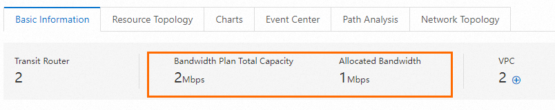
After the configuration is complete, you can view the bandwidth plan and allocated bandwidth on the Basic Information tab.
Connect to the source RDS instance and add the VPC CIDR block of the DR instance to an IP address whitelist of the source RDS instance. For more information, see Configure an IP address whitelist.
You can view the VPC CIDR block on the Database Connection page of the source RDS instance. Example: 192.168.0.0/16.
Step 2: Assess the feasibility of DR deployment
Go to the Instances page. In the top navigation bar, select the region in which the DR instance resides. Then, find the DR instance and click the instance ID.
In the left-side navigation pane, click Cloud Migration/DR Deployment. On the page that appears, click the Feasibility assessment tab.
Set the Scenario parameter to DR Construction and the Source parameter to ApsaraDB RDS Instance. Click Next.
Confirm the configuration of the DR instance and click Next.
In the Configure Source Instance step of the configuration wizard, select all listed items and click Next.
In the Start Feasibility Assessment step of the configuration wizard, configure information about the source instance. The following table describes the parameters.
Parameter
Description
DR Construction Task Name
The name of the DR deployment task. The system automatically generates a name for the DR deployment task. You do not need to modify the generated name.
Region of Source RDS Instance
The region in which the source RDS instance resides. In this example, China (Beijing) is selected.
Name of Source RDS Instance
The ID of the source RDS instance.
IP Address/Domain Name of Source Instance
The internal endpoint of the source RDS instance. You can view the internal endpoint on the Database Connection page of the source RDS instance.
Username
The username of the account that is used to create a DR relationship. In this example, replicatoraccount is used.
Password
The password of the account that is used to create a DR relationship.
Click Create Feasibility Assessment Task.
NoteDuring the feasibility assessment, the status of the DR instance changes to Maintaining Instance.
In the DR Construction section of the page, you can view the status of the feasibility assessment task.
If the status of the feasibility assessment task is Successful, you can perform the operations in Step 3: Create a DR deployment task.
If the status of the feasibility assessment task is Failed, you can click View Report in the Actions column to view and handle the reported errors. For more information about the common errors, see Analyze the feasibility assessment report of DR deployment.
Step 3: Create a DR deployment task
You can perform the following operations only when the status of the feasibility assessment task is Successful.
Go to the Instances page. In the top navigation bar, select the region in which the DR instance resides. Then, find the DR instance and click the ID of the instance.
In the left-side navigation pane, click Cloud Migration/DR Deployment. On the page that appears, click the DR Construction tab.
Click Create DR Relationship.
In the Create DR Relationship dialog box, select the successful feasibility assessment task.
Click Create DR Relationship to create a DR deployment task.
When the DR deployment task is being created, the destination RDS for PostgreSQL instance changes to the Maintaining Instance state. You can view information about the DR deployment task in the task list on the DR Construction tab.
Click the value in the Construction Phase column of the DR deployment task to view the phases that are required to complete the DR deployment task.
If Incremental Data Synchronization is displayed in the Construction Phase column, the DR deployment task is complete.
Click View Logs in the Actions column to view the log details of the DR deployment task.
Optional. Connect to the source RDS instance and execute the
TABLE pg_stat_replication;statement to view statistics on primary/secondary replication.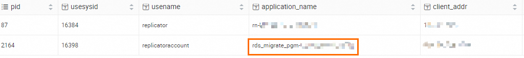
Step 4: (Optional) Configure Private DNS
After you configure Private DNS, you can resolve an internal domain name to the internal endpoint of the source RDS instance or the DR instance in the VPCs of the instances. The internal endpoint can be an IP address or a domain name. For more information, see What is Private DNS? This way, you can use the internal domain name to connect to your database system. If the source RDS instance fails, you can quickly promote the DR instance as the primary instance and map the internal domain name to the DR instance to implement seamless failovers.
Log on to the Alibaba Cloud DNS console.
In the left-side navigation pane, click Private DNS (PrivateZone).
On the Private DNS (PrivateZone) page, choose Built-in Authoritative Module > User Defined Zones.
Click Add New Zone. In the Add Built-in Authoritative Zone panel, configure the required parameters.
Built-in Authoritative Zone: In this example, pg_test_1106 is used.
Alibaba Cloud VPC in Effective Scope of Zone: Select the VPCs of the source RDS instance and the DR instance.
NoteYou can view the VPC on the Database Connection page of the required instance.
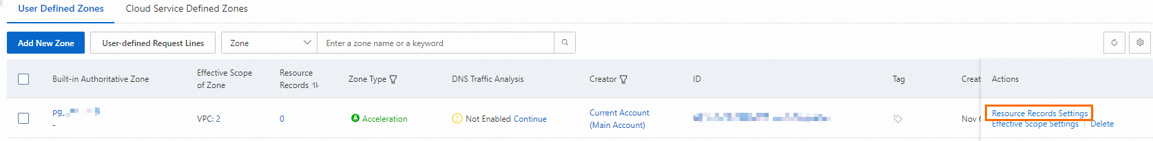
Find the new zone and click Resource Records Settings in the Actions column. The Resource Records Settings page appears.
Click Add Record. In the Add Record panel, configure the required parameters and click OK.
Record Type: Select CNAME.
Hostname: Enter the prefix of a subdomain name. In this example, an at sign (@) is specified for this parameter because the domain pg_test_1106 is used as the subdomain and no prefix is required.
NoteYou can configure subdomains by specifying different prefixes. For example, you can configure a subdomain
api.<domain>for API services and a subdomainpay.<domain>for your payment system. For more information, see Configure a subdomain.Request Line: specifies the source from which DNS queries are sent. In most cases, Default is selected. If you want to return different IP addresses for different DNS requests, you can add other DNS request sources, such as ISP and outbound DNS lines. For more information, see Intelligent DNS resolution.
ImportantYou must add a DNS record for which the Request Line parameter is set to Default. This helps prevent resolution failures when specific DNS requests are not sent from the source specified by the Request Line parameter.
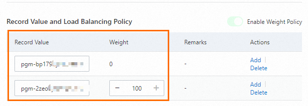
Record Value: In this example, the internal endpoints of the source RDS instance and the DR instance are added as two record values. The weight of the source RDS instance is set to 100, and the weight of the DR instance is set to 0.
In the Change Resource Record Confirmation message, confirm the settings and click OK.
Verify the configuration result of the internal domain name.
Log on to the Elastic Compute Service (ECS) instance that resides in the same VPC as the source RDS instance.
Run the
pingcommand to verify the connectivity of the internal domain name.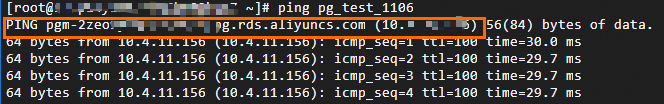
The internal domain name points to the internal endpoint of the source RDS instance.
You can also use the internal domain name to connect to the source RDS instance. If the connection is successful, the internal domain name is configured. For more information, see Connect to an ApsaraDB RDS for PostgreSQL instance.
If the source RDS instance fails, you can modify the DNS records to change the weight of the DR instance to 100 and the weight of the source RDS instance to 0. This way, the internal domain name points to the DR instance to implement seamless failovers. For more information, see Modify DNS records.
Verify the configuration result after modification.
Log on to the ECS instance that resides in the same VPC as the source RDS instance.
Run the
pingcommand to verify the connectivity of the internal domain name.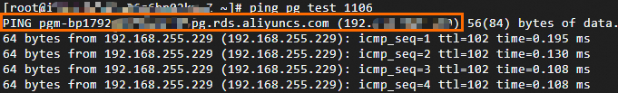
The internal domain name points to the internal endpoint of the DR instance.
You can also use the internal domain name to connect to the DR instance. If the connection is successful, the internal domain name is configured. For more information, see Connect to an ApsaraDB RDS for PostgreSQL instance.