This guide explains how to encrypt traffic on an Express Connect circuit by creating a private IPsec-VPN connection between a customer gateway device and a transit router -- combining static routing on the virtual border router (VBR) with BGP dynamic routing over the VPN connection.
Background information
Before you start, we recommend that you learn about how private traffic is encrypted and transmitted over Express Connect circuits. For more information, see Encrypt Express Connect traffic.
If your customer gateway device supports BGP dynamic routing, we recommend that you configure BGP dynamic routing for both VBRs and private IPsec-VPN connections to encrypt and transmit private traffic over Express Connect circuits. For more information, see Encrypt private traffic over Express Connect with BGP.
Scenario
The following figure shows a use scenario. An enterprise owns a data center in Hangzhou and has a VPC deployed in the China (Hangzhou) region. Applications are deployed on Elastic Compute Service (ECS) instances in the VPC. To expand businesses, the enterprise wants to connect the data center to the cloud. To meet security compliance requirements, the enterprise needs to use Express Connect circuits and transit routers to exchange data between the data center and VPC through private connections. In addition, to prevent data breaches and data tampering, the enterprise wants to encrypt data before transmitting the data to Alibaba Cloud over the Express Connect circuit.
After establishing private connectivity between the on-premises data center and the VPC, the enterprise can create a private IPsec-VPN connection between its customer gateway device and the transit router. This private IPsec-VPN connection encrypts traffic passing through the physical connection, meeting the enterprise's security requirements.

Network plan
When planning the CIDR blocks for your on-premises data center and related network instances, ensure the CIDR blocks do not overlap.
Routing mechanism
You can encrypt private traffic over a physical connection by controlling route selection:
Traffic from the VPC to the on-premises data center:
The transit router learns routes to the data center from both the VBR and the private IPsec-VPN connection. By default, the transit router prefers the VBR route, so traffic flows unencrypted over the physical connection.
To route traffic through the encrypted VPN path instead, use different subnet masks. Add a broader CIDR block (shorter mask) to the VBR, and advertise a more specific CIDR block (longer mask) over the IPsec-VPN connection.
For example, if the data center uses
192.168.0.0/16and the client subnet is192.168.20.0/24, add192.168.0.0/16to the VBR and advertise192.168.20.0/24over the IPsec-VPN connection. The transit router selects the more specific route, directing traffic through the encrypted tunnel.Traffic from the on-premises data center to the VPC:
The data center automatically learns routes to the VPC through the IPsec-VPN connection. You also add a static route for the VPC CIDR block on the customer gateway device with the next hop pointing to the physical connection, then lower its priority so the dynamically learned VPN route takes precedence. Traffic then flows through the encrypted IPsec-VPN connection.
This ensures that the data center and VPC can still exchange data through the Express Connect circuit and transit router when the private IPsec-VPN connection is closed. However, the data is not encrypted in this case.
Basic CIDR block planning
Resource | CIDR block | IP address |
VPC |
|
|
VBR |
|
|
On-premises data center | Client CIDR block: | Client IP address: 192.168.20.6 |
Customer gateway device CIDR blocks:
|
|
BGP CIDR block planning
The CIDR block of the BGP tunnel must fall within 169.254.0.0/16. The mask of the CIDR block must be 30 bits in length. The CIDR block cannot be 169.254.0.0/30, 169.254.1.0/30, 169.254.2.0/30, 169.254.3.0/30, 169.254.4.0/30, 169.254.5.0/30, 169.254.6.0/30, or 169.254.169.252/30. The two tunnels of an IPsec-VPN connection must use different CIDR blocks.
| Resource | Tunnel | BGP tunnel CIDR block | BGP IP address | BGP local ASN |
|---|---|---|---|---|
| IPsec-VPN connection | Tunnel 1 | 169.254.10.0/30 |
169.254.10.1 |
65534 |
| Tunnel 2 | 169.254.20.0/30 |
169.254.20.1 |
||
| Customer gateway device | Tunnel 1 | 169.254.10.0/30 |
169.254.10.2 |
65530 |
| Tunnel 2 | 169.254.20.0/30 |
169.254.20.2 |
Prerequisites
Before you begin, verify that you have:
-
A VPC in the China (Hangzhou) region with applications running on ECS instances. See Create a VPC with an IPv4 CIDR block
-
A customer gateway device that supports IKEv1 and IKEv2. Contact your gateway vendor to confirm
Procedure
Step 1: Connect the data center to a VPC
Step 1a: Deploy an Express Connect circuit
-
Apply for an Express Connect circuit in the China (Hangzhou) region. See Requesting Classic Mode or Overview of hosted connections. This example uses a dedicated physical connection.
-
Create a VBR.
-
Log on to the Express Connect console.
-
In the left navigation pane, click Virtual Border Routers (VBRs).
-
In the top navigation bar, select China (Hangzhou). The VBR and Express Connect circuit must be in the same region.
-
Click Create VBR.
-
In the Create VBR panel, set the following parameters and click OK. For all other parameters, use the default values. See Create and manage VBRs.
Parameter Example value Name VBRPhysical connection information Select Dedicated Physical Connection and choose the Express Connect circuit you deployed VLAN ID 0Alibaba Cloud side IPv4 address 10.0.0.1Data center side IPv4 address 10.0.0.2IPv4 subnet mask 255.255.255.252 -
-
Add a route pointing to the data center on the VBR.
-
On the Virtual Border Routers (VBRs) page, click the VBR ID.
-
Click the Routes tab, then the Custom route entry tab, and click Add route.
-
In the Add route panel, configure the following parameters and click OK.
ImportantUse a short mask (
/16) here. This lets the more specific IPsec-VPN routes (/24) take priority over this route when the tunnel is active.Parameter Example value Next hop type Express Connect Circuit Destination CIDR block 192.168.0.0/16Next hop The Express Connect circuit you deployed -
-
Add a route pointing to the VPC on the customer gateway device. Verify that the interfaces are already configured on the Cisco firewall:
NoteThis example uses Cisco Adaptive Security Appliance (ASA) software version 9.19.1. Commands may vary across versions — refer to your vendor's documentation for your environment. See Configure local gateways. The following Cisco configuration is provided for reference only. Alibaba Cloud makes no guarantees about the performance or reliability of third-party products.
ciscoasa> enable
Password: ********             # Enter the enable mode password.
ciscoasa# configure terminal   # Enter configuration mode.
ciscoasa(config)#

ciscoasa(config)# show running-config interface
!
interface GigabitEthernet0/0                # Connects to the VBR.
 nameif VBR
 security-level 0
 ip address 10.0.0.1 255.255.255.252
!
interface GigabitEthernet0/2                # Connects to the data center.
 nameif private
 security-level 100                         # Must be lower than the interface connecting to Alibaba Cloud.
 ip address 192.168.50.215 255.255.255.0
!
interface GigabitEthernet0/3                # Connects to private IPsec-VPN tunnel 1.
 nameif VPN-IP1
 security-level 0
 ip address 192.168.10.136 255.255.255.0
!
interface GigabitEthernet0/4                # Connects to private IPsec-VPN tunnel 2.
 nameif VPN-IP2
 security-level 0
 ip address 192.168.40.159  255.255.255.0
!

# Static route to the VPC (172.16.0.0/16).
route VBR 172.16.0.0 255.255.0.0 10.0.0.2

# Route to the data center client subnet.
route private 192.168.0.0 255.255.0.0 192.168.50.216
Step 1b: Configure a transit router
-
Create a Cloud Enterprise Network (CEN) instance. In the Create CEN instance dialog box, click Create CEN Only, enter a name, and keep the default settings.
-
Create an Enterprise Edition transit router in the China (Hangzhou) region to connect the VBR and VPC. Keep the default settings.
-
Create a VPC connection.
-
Click Create More Connections to return to the Connection with peer network instance page.
Parameter Value Instance type Virtual Private Cloud (VPC) Region China (Hangzhou) Attachment name VPC-AttachmentNetwork instance Your VPC vSwitch vSwitch 2 and vSwitch 3. If the region has multiple zones, select at least two zones with one vSwitch each. Use idle vSwitches. Advanced settings Default (all advanced features enabled) -
-
Create a VBR connection on the same page. Configure the following parameters and click OK. See Connect a VBR to a transit router.
Parameter Value Instance type Virtual Border Router (VBR) Region China (Hangzhou) Attachment name VBR-AttachmentNetwork instance VBR Advanced settings Default (all advanced features enabled)
Step c: Test the connectivity
After you complete the preceding configuration, the data center is connected to the VPC. You can perform the following steps to test the connectivity.
Make sure that you are familiar with the security group rules for the ECS instances in the VPC and the access control rules for the client in the data center. Make sure that the rules allow the ECS instances in the VPC to communicate with the client in the data center. For more information, see View security group rules and Add a security group rule.
The access control rules for the data center must allow ICMP messages and access from the VPC. The security group rules for the ECS instances must allow ICMP messages and access from the CIDR block of the data center.
Connect to ECS 1 in the VPC. For more information, see Connection method overview.
Run the ping command to ping a client in the data center.
ping <the IP address of a client in the data center>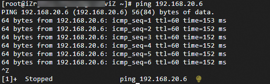
As displayed in the preceding figure, if ECS 1 can receive the response, the data center and VPC are connected.
Step 2: Encrypt private network traffic
After you establish a private connection between the data center and the VPC, create a private IPsec-VPN connection between your customer gateway device and the transit router. Then, configure routes to direct traffic through the IPsec-VPN connection to encrypt the private network traffic.
Step 2a: Create a private IPsec-VPN connection
Add the CIDR block 10.10.10.0/24 for the transit router. For more information, see Transit router CIDR blocks.
A gateway IP address will be allocated from the transit router CIDR block to create a private IPsec-VPN connection. The transit router CIDR block must not overlap with the CIDR blocks of the data center and VPC used for communication.
Create two customer gateways to register the two VPN IP addresses and BGP ASN of the customer gateway device with Alibaba Cloud.
- Log on to the VPN gateway console.
In the left-side navigation pane, choose .
On the Customer Gateway page, click Create Customer Gateway.
In the Create Customer Gateway panel, set the following parameters and click OK.
The following table describes only some of the parameters. Other parameters use the default values. For more information, see Customer Gateway.
Customer Gateway 1
Name: Enter Customer-Gateway1.
IP Address: Enter one of the VPN IP addresses of the customer gateway device, which is 192.168.10.136.
ASN: Enter the BGP ASN of the customer gateway device, which is 65530.
Customer Gateway 2
Name: Enter Customer-Gateway2.
IP Address: Enter the other VPN IP address of the customer gateway device, which is 192.168.40.159.
ASN: Enter the BGP ASN of the customer gateway device, which is 65530.
Create an IPsec-VPN connection.
In the left-side navigation pane, choose .
On the IPsec Connections page, click Bind CEN.
Configure parameters and click OK. The following table describes the parameters.
The following table describes only the key parameters. The default values are used for the other parameters. For more information, see Create and manage dual-tunnel IPsec connections.
Parameter
IPsec-VPN connection
Name
Enter IPsecConnection.
Region
Select the region where the transit router is deployed.
The ipsec-vpn connection is created in the same region as the transit router.
Gateway Type
Select Private.
Bind CEN
Select Same Account.
CEN Instance ID
In this example, the CEN instance that connects the data center and VPC is selected.
The system displays the ID and address range of the transit router that is created in the region. The ipsec-vpn connection attaches to this transit router.
Transit Router
The system automatically displays the transit router of the CEN instance in the current region.
Routing Mode
Destination Routing Mode is selected in this example to control traffic routing.
Enable BGP
Enable BGP.
Local ASN
Enter the BGP ASN of the IPsec-VPN connection, which is 65534.
Tunnel 1
Customer Gateway
Select Customer-Gateway1.
Pre-Shared Key
fddsFF111**** is used in this example.
ImportantThe pre-shared key of the IPsec-VPN connection must be the same as the pre-shared key of the peer gateway device. Otherwise, the IPsec-VPN connection cannot be established.
Encryption Configuration
Use the default values of parameters except for the following parameters.
Set the DH Group parameter in the IKE Configurations section to group14.
Set the DH Group parameter in the IPsec Configurations section to group14.
NoteYou need to select encryption parameters based on the on-premises gateway device to ensure that the encryption configurations for the IPsec connection are the same as those for the on-premises gateway device.
BGP Configuration
Tunnel CIDR Block: Enter 169.254.10.0/30.
Local BGP IP address: Enter 169.254.10.1.
Tunnel 2
Customer Gateway
Select Customer-Gateway2.
Pre-Shared Key
fddsFF222**** is used in this example.
Encryption Configuration
Use the default values of parameters except for the following parameters.
Set the DH Group parameter in the IKE Configurations section to group14.
Set the DH Group parameter in the IPsec Configurations section to group14.
NoteYou need to select encryption parameters based on the on-premises gateway device to ensure that the encryption configurations for the IPsec connection are the same as those for the on-premises gateway device.
BGP Configuration
Tunnel CIDR Block: Enter 169.254.20.0/30.
Local BGP IP address: Enter 169.254.20.1.
Advanced Configuration
In this example, the default settings are used. All advanced features are enabled.
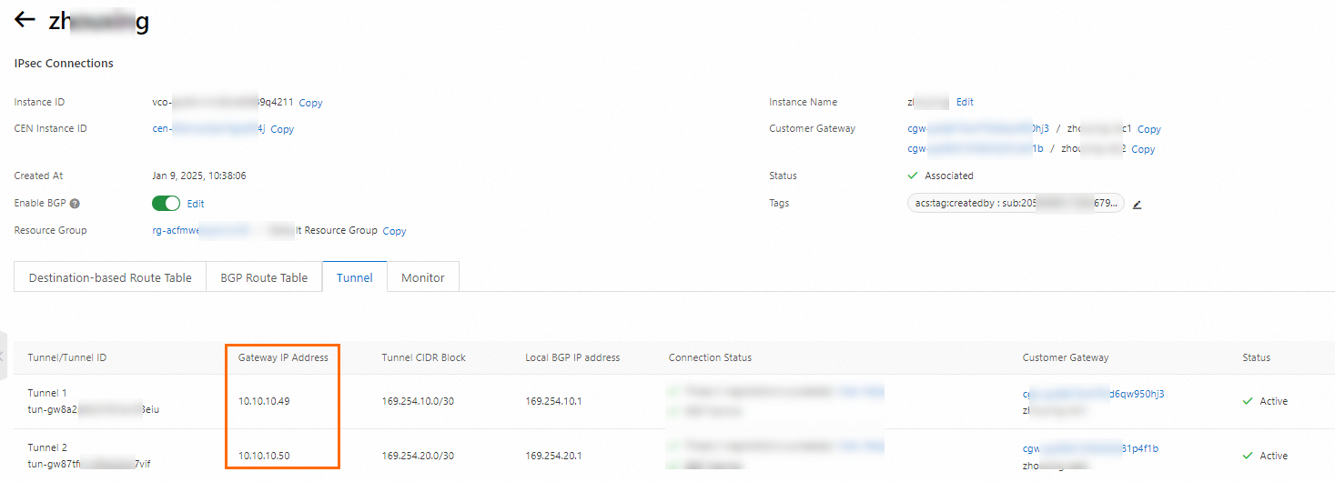
On the details page of the IPsec-VPN connection, you can find that the gateway IP addresses are used to create private IPsec-VPN connections to the customer gateway device.
On the IPsec Connections page, find the IPsec-VPN connection that you create and click Generate Peer Configuration in the Actions column.
The configurations of the IPsec peer refer to the VPN configurations that you need to add when you create the IPsec-VPN connection. In this example, you need to add the VPN configurations to the gateway device of the data center.
In the IPsec Connection Configuration dialog box, copy and save the configurations to an on-premises machine. The configurations are required when you configure the gateway device of the data center.
Configure the customer gateway device.
After you create the IPsec-VPN connection, add the VPN configuration to your customer gateway device to establish a private IPsec-VPN connection with Alibaba Cloud.
After you complete these configurations, your customer gateway device establishes a private IPsec-VPN connection with Alibaba Cloud, but BGP peering is not yet established. You can check the status on the IPsec connection details page in the Alibaba Cloud console. If the connection fails, see IPsec-VPN self-service diagnostics.

Step 2b: Configure routing
After you create the private IPsec-VPN connection, traffic between the data center and the VPC still flows over the unencrypted physical connection. Configure routes to direct traffic through the encrypted IPsec-VPN connection.
Add BGP configurations to your customer gateway device to establish a BGP peering relationship with the IPsec connection. This allows the on-premises data center and the VPC to automatically learn each other's routes through BGP dynamic routing.
#Add BGP configurations to establish BGP peering between the customer gateway device and the IPsec connection.
router bgp 65530
 address-family ipv4 unicast
  neighbor 169.254.10.1 remote-as 65534       #Specify the BGP peer, which is the IP address of Tunnel 1 on the Alibaba Cloud side.
  neighbor 169.254.10.1 activate              #Activate the BGP peer.
  neighbor 169.254.20.1 remote-as 65534       #Specify the BGP peer, which is the IP address of Tunnel 2 on the Alibaba Cloud side.
  neighbor 169.254.20.1 activate              #Activate the BGP peer.
  network 192.168.10.0 mask 255.255.255.0     #Advertise a CIDR block of the on-premises data center. This CIDR block must be more specific than the CIDR block that is added to the VBR instance.
  network 192.168.20.0 mask 255.255.255.0
  network 192.168.40.0 mask 255.255.255.0
  maximum-paths 5                             #Increase the number of BGP ECMP equal-cost routes.
 exit-address-family

#Change the administrative distance of the static route to the Alibaba Cloud VPC (172.16.0.0/16) to a value higher than the BGP route's administrative distance. A higher administrative distance indicates a lower priority. The default administrative distance for eBGP is 20.
route VBR 172.16.0.0 255.255.0.0 10.0.0.2 30
Add custom routes for the transit router.
After you add the preceding routes, the private IPsec-VPN connections will be interrupted. In this case, you need to add specific routes pointing to the VPN IP addresses of the customer gateway device to the route table of the transit route, and set the next hops to the VBR to recreate the private IPsec-VPN connections.
On the Route Table tab of the CEN console, click the Route Entry tab and click Add Route Entry.
In the Add Route Entry dialog box, configure the parameters and click OK. The following table describes the parameters.
Parameter
CIDR block 1
CIDR block 2
Destination CIDR
Enter one of the VPN IP addresses of the customer gateway device, which is 192.168.10.136/32.
Enter the other VPN IP address of the customer gateway device, which is 192.168.40.159/32.
Whether it is a black hole route
Select No.
Next Hop Connection
Select VBR-Attachment.
Add a routing policy to the transit router route table to prevent the private IPsec-VPN connection from advertising VPN IP address routes back to the data center, which would create a routing loop.
Log on to the Cloud Enterprise Network console.
On the CEN Instance page, find the CEN instance that you created and click the instance ID.
On the instance details page, click the transit router ID for the China (Hangzhou) region.
On the transit router details page, click the Forwarding router routing table tab, and then click Routing Policy.
On the Routing Policy tab, click Add Route Map. Configure the route policy and click OK.
This topic describes only the parameters that are relevant to this scenario. For the other parameters, use the default values. See Route policies (Legacy) (for TR only).
Policy Priority: Enter 40.
Associated Route Table: Use the default value.
Direction: Select Egress Regional Gateway.
Match Conditions:
Destination Instance IDs: The ID of the VBR is selected.
Route Prefix: Enter the VPN IP addresses 192.168.10.136/32 and 192.168.40.159/32, and select Exact Match.
Policy Action: Select Reject.
Step 2c: Verify encryption
After completing the configuration, confirm that traffic is flowing through the encrypted tunnel.
-
Connect to ECS 1 and send sustained traffic to a client in the data center:
-
-s 1000: Send 1,000 bytes per packet. -
-c 10000: Send 10,000 requests.
ping <IP address of a client in the data center> -s 1000 -c 10000 -
-
Log on to the VPN Gateway consoleVPN Gateway console.
-
In the top navigation bar, select China (Hangzhou).
-
In the left navigation pane, choose Interconnections > VPN > IPsec Connections.
-
On the IPsec Connections page, click the ID of the IPsec-VPN connection.
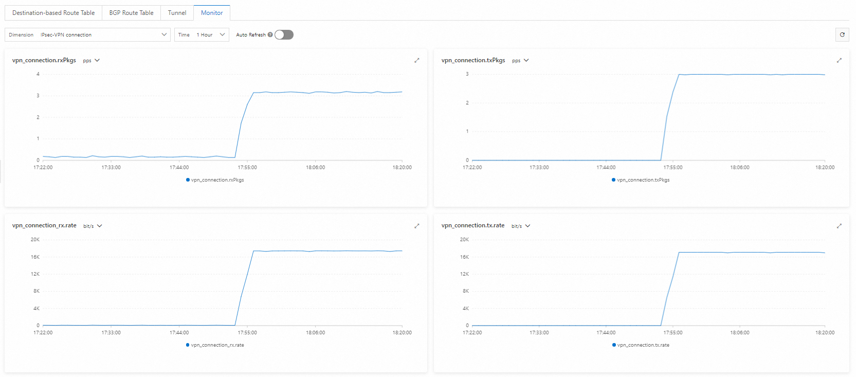
If the details page shows data transfer activity, traffic is encrypted and flowing through the private IPsec-VPN connection.