Logic nodes can help you set the interaction logic between components and components, components and variables, or variables and variables to implement the interaction of all elements in the kanban. This topic describes how to configure and use logical nodes in Blueprint Editor.
Configure logical nodes
Node configuration panel
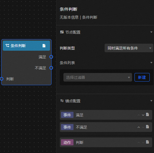
On the blueprint canvas, click the  icon or drag a logical node to the canvas. In the Node Configuration panel on the right, configure the interaction logic for the node. You do not need to configure the global node.
Parameter | Description |
Endpoint Name | The name of the logical node. Different logical nodes have different icons. |
Judgment Type | You can select one of the following types: All conditions are met or Any condition is met. |
Conditions | Set different data filters to achieve the purpose of setting conditions. For more information, see Manage data filters. |
Anchor configuration panel
This topic describes the parameters and operations that are required to configure an anchor point. You can add multiple anchor points to Add Event or Add Action to facilitate interaction with other components. You can click the  icon to rename the anchor point name, click the
  icon and the
  icon to sort the anchor points, click the
  icon to view parameter tips, or click the
  icon to delete an anchor point.
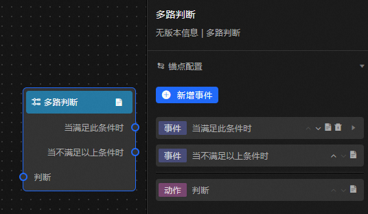
Event /Action | Description |
Judgment | Enter the output of the upstream node for judgment. |
Satisfy | The output result of the upstream node meets the specified conditions. |
Not satisfied | The output result of the upstream node does not meet the specified conditions. |
If Add Event or Add Action is dimmed, the node cannot be added. Add another node or delete the anchor.
Use logical nodes
Log on to the DataV console.
On the console page, select a dashboard and click Edit. The Canvas Editor page appears.
Switch to the Blueprint page.
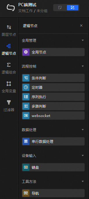
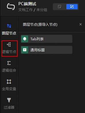
In the left-side navigation pane, click Logical Nodes.
 Note
NoteBefore configuring logical nodes, make sure that you have added corresponding layer nodes. For more information about how to add a layer node, see Configure layer nodes.
In the Logical Nodes panel, drag the required logical node to the canvas.
Logical nodes include Global Management, Flow Control, Data Processing, Device Input, and Tools. For more information about how to use each node and the parameters, see Global Management, Process Control, Data Processing, Device Input, and Tools.