Flow control logic nodes include Single-Path Condition, Conditional Judgment, Multi-Path Judgment, Timer, Serial Execution, WebSocket, and WebSocket-pro. You can configure these nodes in the blueprint editor.
Single condition
The Single-Path Condition node works as an If-condition node. When the configured condition is met, it triggers the Satisfied event.
Triggering an event means that the system runs the logic connected to the event node. The term "trigger" carries this meaning throughout this topic.
Scenarios
For example, to display a layer based on the state of a switch, you can use the Single-Path Condition node to evaluate the current switch state. If the switch is on, the layer is displayed.
Usage
Add the Single-Path Condition node to the blueprint canvas. You can then view its events, actions, and configuration parameters. For more information, see Use Logic Nodes.
Node configuration
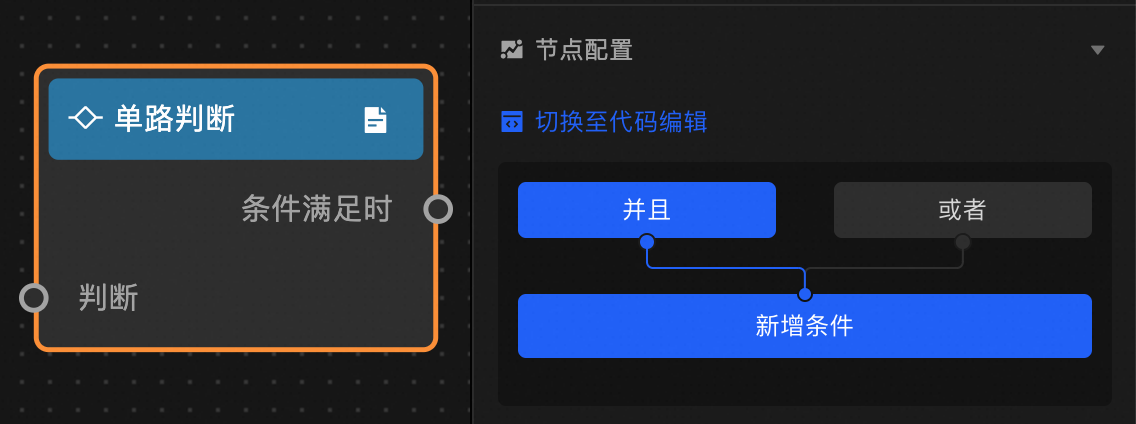
Configure the judgment condition using the visual editor or the code editor.
-
Visual editor: Select the AND pattern to require all conditions to be met, or select the OR pattern to require any condition to be met.
-
Code editor: Add a new data filter and write a filter condition. The condition must return a boolean value. If the result is TRUE, the Condition Met event is triggered. You can add multiple data filters.
Anchor point configuration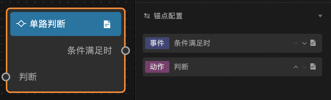
Event and action descriptions
|
Event/Action |
Description |
|
When condition is met |
Triggered when the output from the ancestor node meets the configured condition. You can customize the event name. |
|
Evaluate |
Takes the output from the ancestor node as input for conditional evaluation. You can customize the action name. |
Conditional judgment
The Conditional Judgment node works as an If-Else conditional node. If the specified condition is met, it triggers the Met event. Otherwise, it triggers the Not Met event.
Scenarios
For example, to show or hide two layers based on the state of a switch, you can use a Conditional Judgment node to evaluate the current switch state. If the switch is on, only Layer A is displayed. If the switch is off, only Layer B is displayed.
Usage
Add a Conditional Judgment node to the blueprint canvas. You can then view its events, actions, and configuration parameters. For more information, see Use logic nodes.
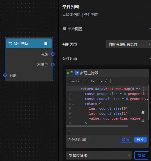
Node configuration
Configuration item descriptions
|
Parameter |
Description |
|
Judgment type |
|
|
Condition list |
Write filter conditions by adding data filters. The filter returns a BOOLEAN value. If the returned value is TRUE, the When Met event is triggered. If the returned value is FALSE, the When Not Met event is triggered. You can add multiple data filters. |
Anchor point configuration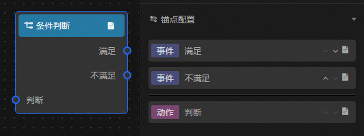
Event and action descriptions
|
Event/Action |
Description |
|
Met |
Triggered when the output from the ancestor node meets the configured condition. You can customize the event name. |
|
Not Met |
Triggered when the output from the ancestor node does not meet the configured condition. You can customize the event name. |
|
Evaluate |
Takes the output from the ancestor node as input for conditional evaluation. You can customize the action name. |
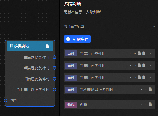
Multi-path judgment
The Multi-path Judgment node works as a Case-When node. It evaluates the output from an ancestor node and triggers an action on the first descendant node whose condition is met.
Scenarios
For example, you can set the color of scatter points on a map based on the current value in a Digital Input Box. Use a Multi-path Judgment node to determine which range the input value falls into and trigger the corresponding color setting, such as red for values greater than 100, yellow for values between 50 and 100, and blue for values less than 50.
Usage
Add the Multi-path Judgment node to the blueprint canvas. You can then view its events, actions, and configuration parameters. For more information, see Use Logic Nodes.
Event and action descriptions
|
Event/Action |
Description |
|
When this condition is met |
Triggered when the condition is met. You can add multiple handlers in the configuration panel. After adding them, the Multi-path Judgment node displays the handlers you added. Different handlers can be connected to different descendant nodes to implement multi-path judgment. |
|
When none of the above conditions are met |
Triggered when none of the configured handler conditions are met. |
|
Evaluate |
Takes the output from the ancestor node as input for multi-path evaluation. |
Configuration item descriptions
|
Parameter |
Description |
|
Procedure |
Create a processing method by adding a new data filter. The method returns a BOOLEAN value. If the result is TRUE, the When This Condition Is Met event is triggered, and no subsequent processing methods are executed. If none of the configured conditions are met, the When The Above Conditions Are Not Met event is triggered. |
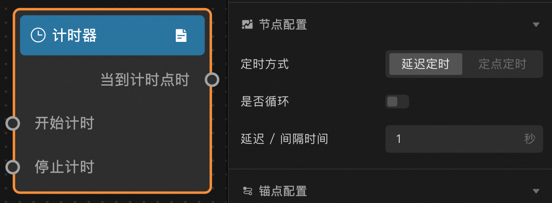
Timer
The Timer node supports delayed timing, fixed-point timing, looped delay timing, and looped periodic timing.
Scenarios
The timer suits any scenario that requires timed execution. When the configured time is reached, the timer node triggers the When time is reached event, outputs the result from the ancestor node, and triggers subsequent actions.
Usage
Add the Timer node to the blueprint canvas to view its events, actions, and configuration parameters. For more information, see Use logical nodes.
Node configuration
Configuration item descriptions
|
Parameter |
Description |
|
Timing mode |
The available modes are Delayed timing and Fixed-point timing. |
|
Loop |
Specifies whether to repeat the timer. When Timing mode is set to Fixed-point timing and Loop is enabled, you can set the start time, interval, and unit in the Fixed-point period. |
|
Delay/Interval time |
The countdown time in seconds. This parameter is valid only when Timing mode is set to Delayed timing. |
|
Fixed-point time |
Counts down to a specific time point and triggers an event. This parameter is valid only when Timing mode is set to Fixed-point timing and Loop timer is disabled. |
Anchor point configuration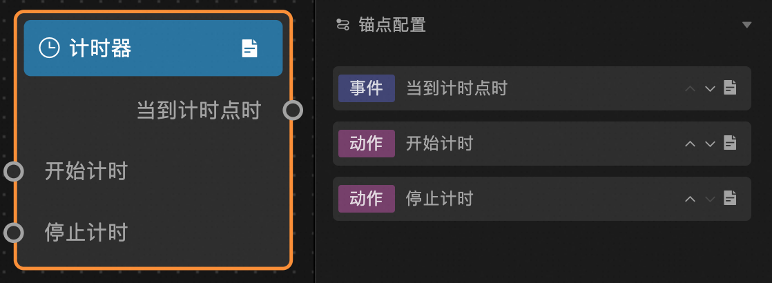
Event and action descriptions
|
Event/Action |
Description |
|
When time is reached |
Triggered when the specified time is reached, causing the descendant node to run an action. If looping is enabled, this event is triggered repeatedly. |
|
Start timer |
Starts the timer. |
|
Stop timer |
Stops the timer. The next time the Start timer action is triggered, the timer restarts from the beginning. This is typically used with a loop timer. |
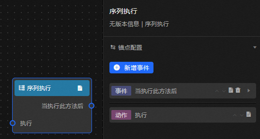
Serial execution
The Serial Execution node processes the output from an ancestor node through its handlers in sequence, triggering a corresponding action for each handler.
Scenarios
For example, when switching between data panels for different scenarios where each scenario has many panels, you might need to first hide the panels for Scenario A and then show the panels for Scenario B. You can use the Serial Execution node to group the data panels by scenario and switch them in sequence: first A, then B.
Usage
Add the Serial Execution node to the blueprint canvas to view its events, actions, and configuration parameters. For more information about how to add nodes, see Use Logic Nodes.
Event and action descriptions
|
Event or Action |
Description |
|
After this handler is executed |
A data handler for the Serial Execution node. You can add multiple handlers in the configuration panel. After adding them, the Serial Execution node displays the handlers you added. The handlers process data in sequence. |
|
Execute |
Takes the output from the ancestor node as input for processing. |
Configuration item descriptions
|
Parameter |
Description |
|
Processing Method |
You can write a processing method by adding a new data filter. The method returns a Boolean value. If the return value is TRUE, the After This Method Is Executed event is triggered. You can add multiple processing methods. Each processing method is calculated independently. The input for all methods is the output from the previous node. The output of each method is its own calculated result, and the methods do not affect each other. |
WebSocket node
The WebSocket node enables inter-screen communication. Each message consists of a custom message name and data from the ancestor node's output.
Scenarios
The WebSocket node transmits commands and data between multiple clients, such as between a large screen and a mobile client, or between a large screen and a touch screen client.
Usage
Add the WebSocket node to the blueprint canvas to view its events, actions, and configuration parameters. For more information about how to add a node, see Use logic nodes.
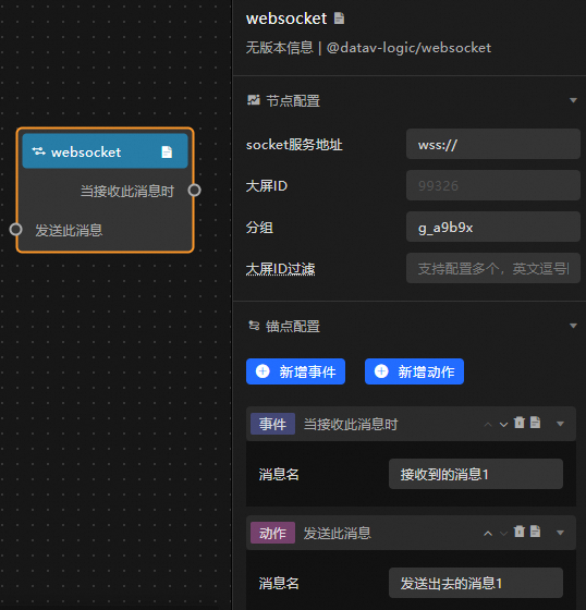
Node configuration
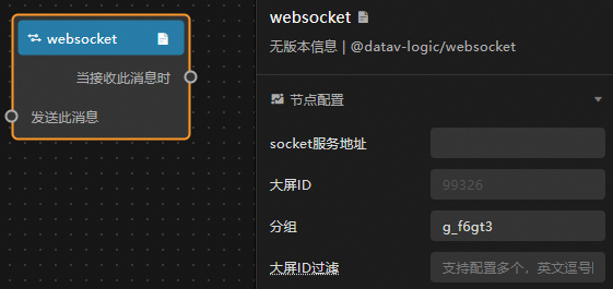
Configuration item descriptions
|
Parameter |
Description |
|
socket service endpoint |
The endpoint of the backend socket service. |
|
Screen ID |
The ID of the screen where this WebSocket node is located. The platform automatically detects and fills this in. |
|
Group |
WebSocket node messages are broadcast only within the same group under the same socket service. Typically, a single group name is used for the same project. To ensure the group name is unique, the platform automatically generates a default group name. You can also change it as needed. |
|
Screen ID filter |
By default, messages sent by a WebSocket node are received by all screens within the same group. You can use this parameter to specify which screens should filter out WebSocket node messages. The configured screens will not receive the message. Note
You can enter multiple screen IDs, separated by commas (,). |
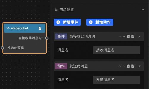
Anchor point configuration
Event and action descriptions
|
Event/Action |
Description |
|
When this message is received |
This event is triggered when the WebSocket node receives a message with the same name from another client. You can edit the received message name in the configuration panel. Click the add event button on the right to add a received message. Click the |
|
Send this message |
Inputs the output from the ancestor node and sends it to other clients. You can edit the sent message name in the configuration panel. Click the add action button on the right to add a sent message. Click the |
 icon on the right to delete a received message.
Configuration example
Message Registration
The WebSocket node sends messages in the following format.
{
  event: "register",
  data: {
    sid: "99326",                                      // Screen ID
    group: "g_a9b9x"                                  // Auto-generated group name
  },
  callback: "callback_15832235175585251131307383912" // Current registration timestamp, auto-generated
}
After the WebSocket service receives the registration message, it must return the following message to complete the registration.
{
  event: "callback_15832235175585251131307383912",   // Return the same registration timestamp
  data: {
    isError: false,                                  // Set to false
    data: "ok"
  }
}
Send a message
The WebSocket node sends messages in the following format.
{
  event: 'broadcast',
  data: {
    event: "sent_message_1",                         // Sent message name
    data: {}                                         // data can be in any format
  }
}
Receive a message
The WebSocket node receives messages in the following format.
{
  event: "broadcast_received_message_1",                  // broadcast_${received_message_name}
  data: {}                                          // data can be in any format
}
Troubleshooting
If you cannot connect to the WebSocket service, troubleshoot the issue as follows:
-
A WS service cannot be accessed directly over the HTTPS protocol. You must use a WSS service. After you use your own SSL Certificate to proxy the WS service endpoint, you can access the service over HTTPS.
-
Press F12 to open the browser's developer tools. On the Network tab, view the connection information on the WS tab. Check for cross-domain configuration errors and verify that the `Sec-WebSocket-Protocol` header in the connection response is set to `echo-protocol`.
-
After a successful connection, pass parameters according to the message format described in this document.
WebSocket-pro node
The WebSocket-pro node enables inter-screen communication with more granular configuration options than the WebSocket node. Each message consists of a custom message name and data from the ancestor node's output.
Scenarios
Like the WebSocket node, the WebSocket-pro node transmits commands and data between multiple clients.
Usage
Add the WebSocket-pro node to the blueprint canvas to view its configuration parameters. For more information about how to add nodes, see Work with logical nodes.
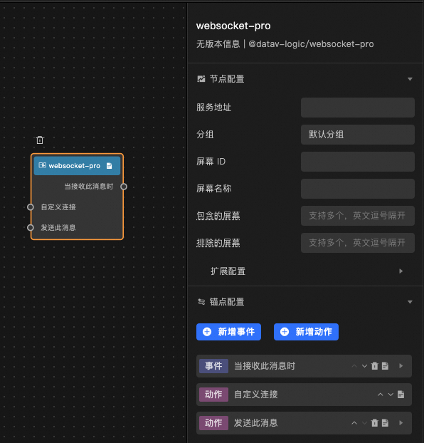
Node configuration
 Configuration item descriptions
|
Parameter |
Description |
|
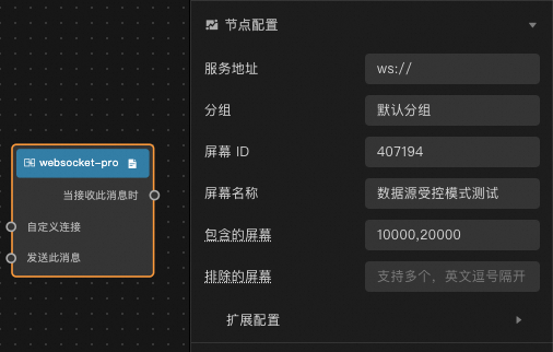
Service endpoint |
The endpoint of the backend socket service. |
|
Group |
WebSocket-pro node messages are broadcast only within the same group under the same socket service. Typically, a single group name is used for the same project. |
|
Screen ID |
The ID of the screen where this WebSocket-pro node is located. Enter a custom ID. |
|
Screen name |
The name of the screen where this Websocket-pro node is located. Enter a custom name. |
|
Included screens |
When a message is sent, all screens in the same group can receive it by default. You can add screen IDs to this configuration to specify which screens should receive the message. |
|
Excluded screens |
When a message is sent, all screens in the same group can receive it by default. You can add screen IDs here to specify screens that should not receive the message. This has a higher priority than Included screens. |
|
Receive Message |
Specifies the name of the message that the websocket-pro node sends to other endpoints. Click the Add Event button on the right to add a received message. Click the Received Message ID: Equivalent to the event field in the WebSocket message content. If the field is matched, the corresponding message is accepted. Received Message Alias: The name displayed for the anchor on the blueprint node. Processing Method: A serial data processing method. You can add multiple processing methods in the configuration panel. After you add the methods, the Serial Data Processing node displays the methods that you added. These methods work together to process data, where the input of each method is the message response content and the output serves as the input for descendant nodes. Received Message Alias: The name displayed for the anchor point on the blueprint node. Processing Method: The serial data processing method. You can add multiple processing methods in the configuration panel. After you add the methods, they are displayed in the Serial Data Processing node. The methods work together to process data, where the input for each method is the returned message content and the output is the input for descendant nodes. |
|
Send Message |
The name of the message that this WebSocket-pro node sends to other clients. Click the add action button on the right to add a sent message. Click the Sent message ID: The value of this configuration item is used as the `event` value in the message body when sending a message. Sent message alias: The name displayed on the anchor point of the blueprint node. Handler: A serial data processing method. You can add multiple handlers in the configuration panel. After adding them, the Serial Data Processing node displays the handlers you added. The handlers work together to process data. The input for the handlers is the message response content, and the output is the input for the descendant node. |
|
Advanced settings |
Other configurations for the screen where the WebSocket-pro node is located. Register broadcast message: Registers a broadcast message for the current screen to facilitate communication. Disconnect after no response: Sets the time after which the connection is automatically disconnected if the network service does not respond. Heartbeat detection: Sets up heartbeat detection for the network communication to ensure the connection is always active. Heartbeat detection interval: Sets the time interval for checking the communication connection status. |
Anchor point configuration
 Event and action descriptions
|
Event/Action |
Description |
|
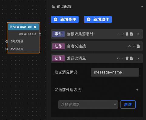
When this message is received |
The event that is triggered when this message is received. Set the Received message ID and Post-receive handler to receive messages from other screens. |
|
Custom connection |
Sets a custom connection for network communication. |
|
Send this message |
When sending this message, set the Sent message ID and Pre-send handler to send it to different screens. |
Configuration example
Message registration
The WebSocket-pro node sends messages in the following format.
{
	"source":"407194",
	"target":["10000","20000"]
	"data":{
		"name":"Data source controlled mode test",
		"group":"Default group",
		"hasCbMsg":true,
		"disconnectTime":60000
	},
	"event":"register"
}
After the WebSocket-pro service receives the registration message, it must process the message internally. If the registration is successful, the client's `hasCbMsg` parameter determines whether to send an acknowledgement to the accepter. If the client fails to register within 10 s, the connection to that client is disconnected. The acknowledgement message has the following format:
{
  "event":"register",
  "source":"407194",
  "data":{
    "isError":false,
    "data":"ok"
  }
}
Heartbeat detection
If heartbeat detection is enabled for the WebSocket-pro node, the required acknowledgement format is as follows.
{
  "event": "heartbeat",
  "data": {
    "group": "Default group",
    "hasCbMsg":true,
    "disconnectTime": 60000
  }
}
Send/Receive messages
The WebSocket-pro node uses the same structure for sending and receiving messages. The format is as follows.
{
  "event":"send_test",
  "source":"407194",
  "target":["10000","20000"],
  "data":{
    "zoom":12
  }
}For the heartbeat, disconnect and reconnect, included screens, and excluded screens configurations of the WebSocket-pro node to take effect, the server-side must be customized to handle the message body structure sent by the client.