X-Engine is an Alibaba proprietary online transaction processing (OLTP) database storage engine. It is widely used in Alibaba's core businesses, including DingTalk, core transactions, and Alimama. This engine significantly reduces storage overheads while providing high performance.
After being tested and optimized in high-load scenarios such as Alibaba Double 11, RDS for MySQL with X-Engine will soon provide services to external customers on Alibaba Cloud, bringing its technical benefits to Alibaba Cloud users. The paper, "X-Engine: An Optimized Storage Engine for Large-scale E-Commerce Transaction Processing" introduces the system architecture and core design of X-Engine. This paper was presented in the SIGMOD 2019 Industrial Track.
Recently, FPGA-Accelerated Compactions for LSM-based Key-Value Store, another project from the X-Engine team, was accepted by the Research Track in the 18th USENIX Conference on File and Storage Technologies (FAST'20). FAST'20 is a CCF class-A conference and a top conference in the storage field, with a 16% acceptance rate in 2020.
This article will give a brief introduction to this new project. X-Engine adopts the log-structured merge-tree (LSM-tree) architecture and is extensively optimized for modern multi-core, large-memory, and high-speed storage servers. For example, it adopts a large number of lock-free designs internally, which provides high scalability.
Before explaining the paper, let's analyze the development trends of server-side hardware in the era of X-Engine and the server computing and storage resource requirements of storage engines based on the LSM-tree architecture. This information will make it easier for you to understand why it is necessary to introduce dedicated computing devices other than CPUs for databases.
In recent years, server-side hardware, including processors and storage, has developed rapidly. In terms of CPUs, Intel's Xeon CPU family has been upgraded under the first round of the "Process-Architecture-Iteration" model in the 14 nanometer (nm) process. In the 10 nm process, a new Tiger Lake microarchitecture has been released.
With the common increase in the number of CPU cores today, Tiger Lake microarchitecture provides a clock frequency that is approximately 30% higher than that of Skylake microarchitecture, larger L1 and L2 caches and a greater cache line. It adopts an L4 cache based on high bandwidth memory (HBM) technology and provides faster I/O. These breakthroughs represent a sharp improvement in CPU processing capabilities. Looking ahead, Intel is expected to launch a new round of iteration in 2021 and release its 7 nm processor.
In addition to CPUs, new field-programmable gate arrays (FPGAs), GPUs, and various AI processors have emerged one after another. In 2019, Alibaba released the Hanguang 800 processor with a peak inference performance of 78,563 images per second (IPS). In addition to constant iterations and upgrades, conventional heterogeneous accelerators have also developed increasingly mature hybrid architectures, such as CPU FPGA (for example, Intel Arria series FPGAs) and FPGA-accelerated NVMe SSDs (for example, BittWare 250). In terms of storage, the development and application of the 3D XPoint technology, which is nearly a thousand times faster than the conventional NAND flash memory, has greatly improved the performance of both non-volatile memories (NVMs) and SSDs.
The latest Intel Optane SSDs provide a random read and write performance of 550,000 input/output operations per second (IOPS), sequential read and write speeds of 2,500 MB/s and 2,200 MB/s respectively, and a read and write latency of 10 µs. The following figure shows the peak I/O performance of the new Intel SSDs released each year over the last decade. We see great improvements in both the sequential I/O and random I/O performance.
In our industrial practices, the typical server used three years ago could only provide a sequential read speed of 2.4 GB/s. On our latest servers purchased this year, the sequential read speed reached 12 GB/s during testing.
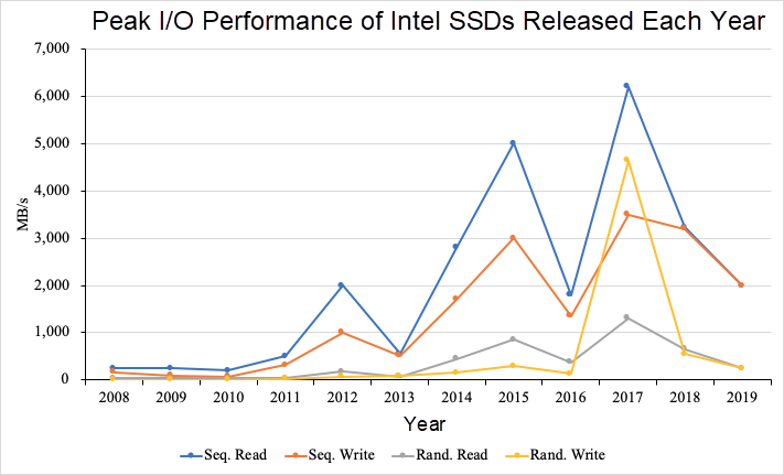
Peak I/O performance of Intel SSDs released over the last decade
New trends in hardware and changes in underlying hardware performance often change performance limits in upper-layer software, especially the basic software devices that directly interface with storage hardware devices, such as database storage engines. With the continuous improvement in I/O performance, database algorithms that used to be restricted by I/O performance gradually become restricted by computing resources, and vice versa. In this project, we found that the compaction operation in the LSM-tree storage engine provides an exact example of shifting the cause of performance limit from I/O to computing resources. The following section discusses this in detail.
In the LSM-tree architecture, write operations are first inserted into the memory. When the usage of the memory reaches the threshold, data is written to the disk and merged with the data in the disk, whose process is similar to that of the merge sort algorithm. The data in the disk is organized hierarchically. When the data at a level reaches the threshold, it is merged with the data at the next lower level, as shown in part (a) of the following figure.
This method has two benefits:
1) Write operations, including insert, update, and delete operations, are converted to append operations. The original data is not updated, so the write performance is superior to storage engines such as InnoDB.
2) The data is stored and sorted hierarchically. Each block is compact and free of holes. This facilitates compression and has remarkable storage cost advantages.
The data hierarchy of X-Engine is similar to that of LevelDB and RocksDB storage engines that use the LSM tree. Data is first written to the memtable. After the memtable is filled with written data, the memtable is converted to an immutable memtable. Then, the immutable memtable is flushed to the disk for persistent storage.
In X-Engine, the data in the disk is also organized by levels. Each level is generally divided into multiple sequential segments of a fixed size. X-Engine uses Extents, which are similar to SSTables in RocksDB. Each Extent is further divided into multiple data blocks. Data in data blocks is generally stored through prefix encoding, and each Extent uses an index block to index the data blocks, as shown in part (b) of the following figure.
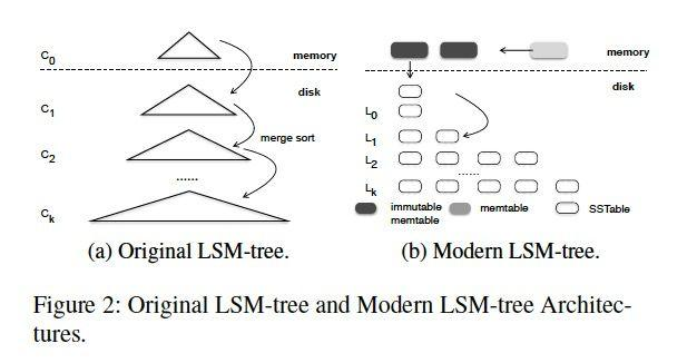
The flush and compaction threads in the background merge memory data with disk data. When the volume of data at each level reaches its threshold, the data is merged with the data at the next lower level. This process is called compaction.
Prompt compaction is very important. The LSM-tree architecture may be deformed due to too many accumulated levels under high loads of continuous highly intensive data writes. This causes serious problems for read operations. When a piece of data is associated with multiple sequence numbers (SNs), read operations need to sequentially scan each level and merge the data to generate the results. The compaction operation merges multi-SN data in a timely manner and deletes the data with earlier SNs, to maintain a healthy read path length. This effectively releases storage space and improves system performance.
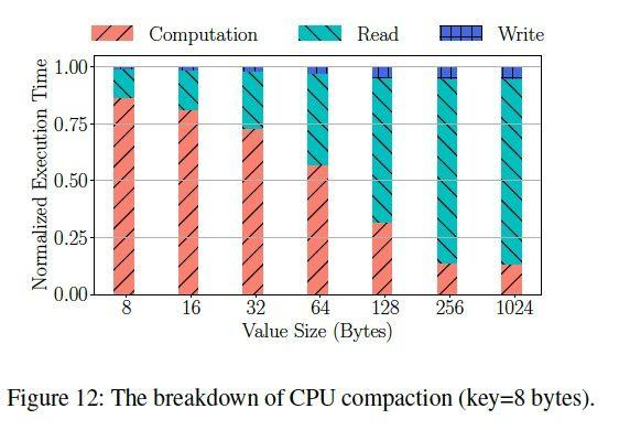
The following figure shows a breakdown of the compaction execution time for different key-value (KV) lengths. When a KV is less than or equal to 64 bytes in length, the computing time accounts for more than 50% of the total execution time of a compaction operation. In recent years, the read and write performance of storage devices has improved rapidly, but the CPU clock speed increased slowly. As a result, the computing time accounts for an increasingly larger proportion of the total execution time of a compaction operation. Additionally, in X-Engine, all data blocks are compressed for storage. The CPU usage of compression makes the performance limit caused by computing resources even more severe.
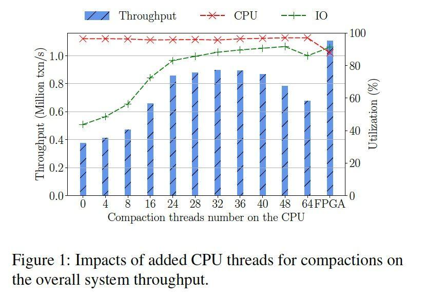
The following figure shows the long-term operating performance and resource utilization in X-Engine. The key is 8 bytes and the value is 32 bytes. The ramp-up period is 1 hour, and the observation window is 2 hours. According to the figure, when the read to write ratio is 3:1, the system may reach the peak performance with 32 compaction threads.
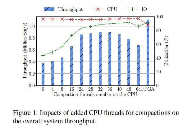
As the number of compaction threads increases in the background, the performance change is parabolic. This illustrates two issues:
1) Prompt compaction is necessary to keep the system performance at a high level. Otherwise, the accumulation of LSM-tree levels will seriously deteriorate the system performance. When 32 threads are configured, X-Engine provides approximately twice the performance as with 8 threads.
2) When CPU resources are limited, the compaction operation needs to contend with transaction processing threads in the foreground for computing resources. System performance deteriorates severely due to resource contention when more than 32 compaction threads are configured.
To process compaction tasks in a timely manner, we can set more compaction threads. However, when excessive compaction threads contend for computing resources, this adversely affects transaction processing threads in the foreground, which decreases the throughput. When the speed at which transaction processing threads in the foreground generate new data is balanced with the speed at which compaction threads in the background eliminate accumulated data, the system achieves balanced performance. However, this performance is usually far lower than the peak performance of databases.
Compaction is required but not necessarily done by the CPU. A compaction task includes the reading, decoding, merge sort, encoding, and write-back stages of multiple data blocks. For a single compaction task, the later stages depend on the data of earlier stages. However, there are no data dependencies between multiple tasks. Therefore, the throughput is increased through a pipeline.
By offloading the compaction operations to an FPGA that is suitable for processing pipeline tasks, the CPU is fully used to process complex transactions, releasing computing resources from background tasks. In this way, the database system always processes transactions at peak performance.
The FPGA programmable acceleration card (PAC) that we use is connected to the server through the PCIe interface. It cannot gain access to the memory and disks as easily as the CPU on the server. In addition, an FPGA has powerful computing capabilities, but the latency of each access is similar to that of an I/O device. These features indicate that we cannot directly apply the preceding CPU-specific compaction algorithm to an FPGA.
To adapt this solution to the FPGA PAC, we first deployed the CPU-specific streaming compaction operation to a batch mode. The CPU splits a compaction operation into tasks of a specific size, each of which can be executed concurrently. In this way, we fully utilize the concurrent processing capabilities of multiple compaction units (CUs) on the FPGA PAC.
In X-Engine, we designed a task queue to cache compaction tasks to be executed and used a driver to deliver the tasks to the CUs on the FPGA for execution. The execution results are cached in the result queue and wait for the CPU to write it back to the persistent storage.
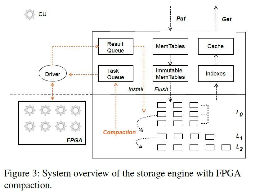
The scheduler creates compaction tasks, distributes these tasks to the CUs for execution, and writes the compaction results back to the disk. We have designed three types of threads to complete the entire process:
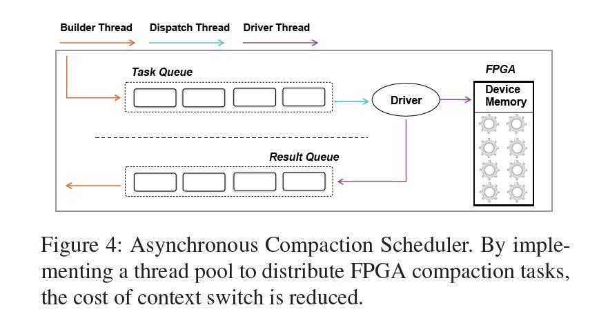
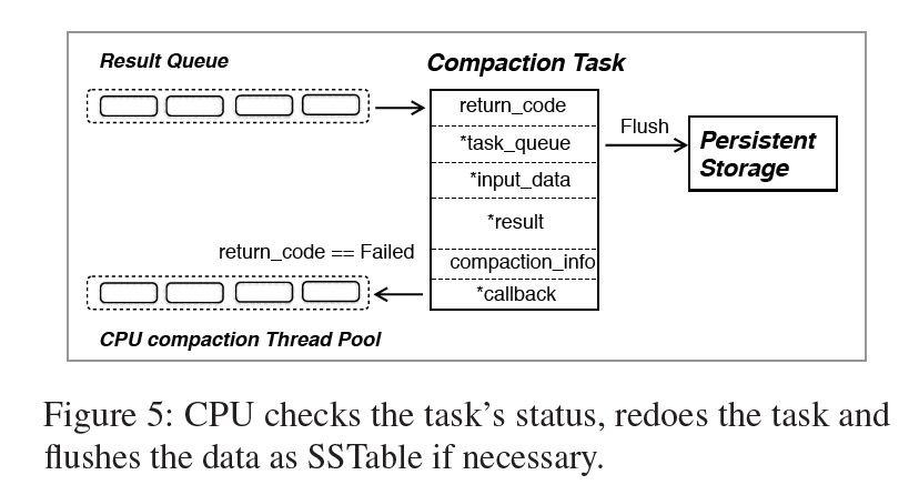
1) Builder Thread: This thread splits the to-be-merged Extents into compaction tasks by range. The structure of each compaction task maintains required metadata, including the task queue pointer, the start address of input data (this is required during cyclic redundancy check (CRC), which is performed to ensure data correctness when the data is transmitted to the FPGA), the write-back address of the compaction result, and the callback function pointer of the subsequent logic.
In addition, each task contains a return code that indicates whether the compaction task was successful. When a failure code is returned, the CPU is called to execute the task again. According to data from online operations, only about 0.03% of tasks have to be re-executed by the CPU, and these tasks are mainly caused by an excessively long KV.
2) Dispatcher Thread: An FPGA contains multiple CUs, so we need to design corresponding distribution algorithms. Currently, we adopt a simple round-robin distribution policy. The sizes of distributed compaction tasks are similar. Tests have shown that this method balances the utilization of different CUs.
3) Driver Thread: The driver thread transmits data to the FPGA and notifies the CUs to start working. After completing the tasks, the CUs are interrupted. Then, the driver thread transfers the results back to the memory and adds the tasks to the result queue.
A CU in an FPGA corresponds to the implementation logic of compaction in CPU. Multiple CUs can be deployed on one FPGA and scheduled by a driver. A CU consists of a decoder, a KV ring buffer, a KV transfer, a key buffer, a merger, an encoder, and a controller.
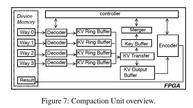
The design of the decoder module is related to the compaction policy of the LSM tree. Currently, a CU contains four decoders. X-Engine adopts a tiering policy, to ensure that multi-way merging is possible. According to actual cases, 2- to 4-way merging is most common, and the design with 4-way merging is more efficient than that with 2-way merging, with the performance being improved by three times, and the hardware resource consumption being increased by about 40%. The decoder module decodes the preamble-encoded KV pairs and then caches them to the KV ring buffer.
A KV ring buffer consists of thirty-two 8 KB slots. In each slot, 6 KB is used to store KV data, and 2 KB is used to store KV metadata such as the KV length. Each KV ring buffer has three states: FLAG_EMPTY, FLAG_HALF_FULL, and FLAG_FULL, which identify whether the ring buffer is empty, semi-full, or full respectively. Based on the number of cached KVs, we can decide whether to continue the pipeline or temporarily suspend the decoder until downstream consumption ends.
The KV transfer and key buffer transfer KVs. Value comparison is not required during merge sort, and therefore, only key values need to be cached. The merger merges the keys in the key buffer. As shown in the following figure, the key of way-2 is the smallest. The controller instructs the KV transfer to transfer the corresponding KV from the KV ring buffer to the KV output buffer (which is similar to the KV ring buffer in terms of structures) and moves the read pointer of the KV ring buffer forward to obtain the next KV. Then, the controller instructs the merger to perform a comparison for other keys.
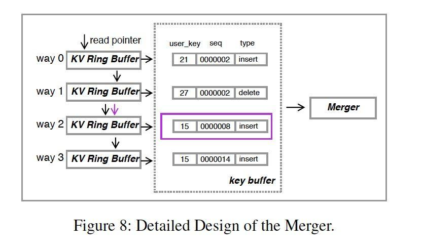
The encoder module preamble-encodes the KV output by the merger, organizes the KV into the data block format, and writes it to the FPGA storage.
To control the processing speed at each stage, we introduced the controller module. The control module maintains the read and write pointer of the KV ring buffer and detects any discrepancy between the upstream and downstream processing speeds of the pipeline based on the status of the KV ring buffer. It can pause or resume the corresponding module to ensure that the pipeline operates efficiently.
Ensuring data consistency is the basic function of a database engine. However, heterogeneous computing devices bring additional variables together with new risks. In the overall architecture design of X-Engine, we considered risks such as FPGA computing device failure and bit changes during transmission. In terms of disaster recovery, we have done the following for X-Engine:
1) X-Engine detects whether any FPGA PAC is deployed on the server and whether the current FPGA PAC is available. X-Engine detects whether the compaction, compression, and decompression firmware are loaded to the current FPGA PAC and whether the current FPGA PAC is alive. The compaction logic and compression logic of X-Engine for CPUs can serve as a backup. If the FPGA suddenly becomes disconnected during operating, X-Engine can smoothly failover to the CPU mode. In this case, the peak performance is slightly lower, but the stability is not affected. After failing over to the CPU mode, X-Engine periodically detects the availability of the FPGA PAC and switches to the FPGA acceleration mode once possible.
2) CRC values are saved in all steps of a CU. After the input and output of the compaction task are transmitted between the FPGA storage and the system memory, the CRC values are verified for consistency. This ensures that no bit-changes occur during the transfer.
3) X-Engine is robust to the failure of some compaction tasks. If a single task fails due to a memory read or write timeout error, X-Engine retrieves the execution result, re-executes the failed task by using the CPU and obtains the execution result. This design also provides another advantage. The implementation of the compaction firmware logic of the FPGA PAC involves register allocation and logical wiring on the chip. Processing records with a particularly long key or value makes the logic computing on the FPGA less efficient.
Therefore, our implementation based on the FPGA only supports KV records of a specific length. When a KV record is ultra-long, an error is directly returned and the task is handed over to the CPU. This prevents the FPGA from processing long fields, such as TEXT and BLOB fields that appear in some databases. In this way, we can process long KVs while ensuring high performance. According to the online operating results of X-Engine, only approximately 0.03% of tasks failed. This proves that our ideas work in practice.
All the experiments in this article were performed on two Intel Xeon Platinum 8163, 2.5 GHz, 24-core, two-way hyper-threading processors with 512 GB DDR4 2133 memory. The disk contains a RAID-0 array that consists of 10 SSDs. The host runs on Linux OS 4.9.79. The FPGA FAC model is 200 MHz Xilinx VU9P. The FPGA provides 16 GB of memory and is connected to the host through PCIe Gen3 x16. A total of eight CUs are configured on the FPGA.
We designed a unit test to compare the throughput during compaction when a single CU is used and when a single CPU is used. We loaded four paths with a total of 4 million records and triggered compaction. In different KV scenarios, the acceleration rate of the FPGA ranges from 200% to 500% during compaction.
To help quantitatively evaluate the throughput of each module in the pipeline, we also modeled the processing speed of the CU. In fact, it is very important to precisely control the execution time of compaction in the FPGA and the CPU. Based on the theoretical model, we can estimate the number of CUs required for a specified compaction throughput. The difference between the result calculated by the model and the result of the unit test was less than 20%.

To evaluate the performance, we use DbBench, with workloads distributed through zipf 1.0 and a default read-write ratio of 3:1. We load 32 subtables corresponding to an LSM tree, with each subtable containing 200 million data entries. We set the memory size to 70 GB, the key size to 8 bytes, and the value size to 32 bytes. This configuration is a common online configuration. The ramp-up period is 3,600 seconds and the evaluation period is 7,200 seconds for each test.
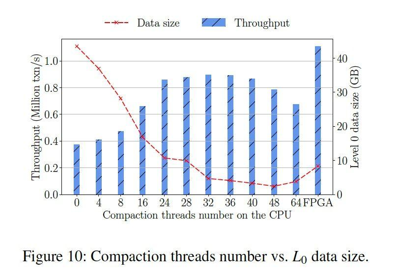
When the FPGA PAC is used, the performance of X-Engine is improved by approximately 25% as compared with that when a 32-thread CPU is used, but CPU usage is reduced by about 10%. Although the throughput during compaction based on a CPU containing over 32 threads is higher than that based on an FPGA PAC, the contention for computing resources occurs. The contention accelerates data digestion in terms of data volume but deteriorates the performance.
As application loads are constantly changing and the hardware environment is constantly evolving, storage engine development is seeking for the optimal balance between cost and performance.
The prosperity of the LSM-tree ecosystem is the result of the two factors described previously. On the one hand, user loads gradually become write and point read-intensive (WPI). The explosive growth in data volumes and the increase in the proportion of writes promote the widespread of LSM-tree storage engines. On the other hand, the rapid development of storage medium technology, such as SSDs and NVMes, has increased the throughput of the persistence levels to new heights. The cause of the performance limit of the storage engine has begun to shift from I/O to the CPU, which also brings many new challenges.
By using new hardware to overcome the performance limit of storage systems, we have only taken a small step forward. There are still many significant problems to be figured out in better ways:
Is faster compaction better? Between timely compaction and the avoidance of cache misses caused by the compaction of hotspot data, timely compaction seems to be an apparently better solution. However, this needs careful consideration.
Dedicated resources are a double-edged sword. To increase the resource utilization of an FPGA when the compaction load is low, we can consider sharing hardware resources among multiple instances and IP addresses. But the critical issue is to determine which solution is more practical. It will take the more practical experience to find the answer to this question.
In a word, the road ahead is long and difficult.
This project was completed with support from the X-Engine team of Alibaba Database Product, the custom computing team of Alibaba Infrastructure Service (AIS), Damo Academy Database, Storage Lab, and Alibaba-Zhejiang University Joint Research Institute of Frontier Technologies (AZFT). I would like to express my gratitude to the researchers who participated in this work and the instructors who provided guidance on this paper. I believe that more cooperative achievements are forthcoming in the future.
Read-only Instance Learner in the 3-node Enterprise Edition of RDS for MySQL
Learn How PolarDB Is Supporting Business Expansion in the Gaming Industry
ApsaraDB - May 14, 2020
ApsaraDB - October 21, 2020
ApsaraDB - November 16, 2020
ApsaraDB - October 22, 2020
ApsaraDB - November 17, 2020
ApsaraDB - December 26, 2023
 ApsaraDB for OceanBase
A financial-grade distributed relational database that features high stability, high scalability, and high performance.
Learn More ApsaraDB for Cassandra
A database engine fully compatible with Apache Cassandra with enterprise-level SLA assurance.
Learn More ApsaraDB for HBase
ApsaraDB for HBase is a NoSQL database engine that is highly optimized and 100% compatible with the community edition of HBase.
Learn More Storage Capacity Unit
Plan and optimize your storage budget with flexible storage services
Learn MoreMore Posts by ApsaraDB