Route internet-bound traffic from multiple virtual private clouds (VPCs) through a single Internet NAT gateway. Traffic from spoke VPCs flows to a transit router, which forwards it to the hub VPC where the NAT gateway translates addresses and sends packets to the internet. This lets you centralize internet egress without deploying a separate NAT gateway in each VPC.
How it works
Spoke VPCs (those without a NAT gateway) send all outbound traffic to the transit router via a 0.0.0.0/0 route in their VPC route table. The transit router holds a static route that points 0.0.0.0/0 to the hub VPC connection. Traffic arriving at the hub VPC reaches the Internet NAT gateway, which applies Source Network Address Translation (SNAT) rules to translate private IP addresses to an Elastic IP Address (EIP) before forwarding packets to the internet.

Example scenario
A company has two VPCs in the China (Chengdu) region: VPC-A hosts the Internet NAT gateway and ECS1, while VPC-B hosts ECS2. Both VPCs need internet access. Rather than deploying a separate NAT gateway in VPC-B, the company attaches both VPCs to a transit router, making VPC-A the centralized internet egress point for both.
| VPC | vSwitch | Zone and CIDR block | Deployed resource |
|---|---|---|---|
| VPC-A | vSwitch-A1 | Chengdu Zone A, 192.168.10.0/24 | Internet NAT gateway |
| VPC-A | vSwitch-A2 | Chengdu Zone B, 192.168.20.0/24 | ECS1 |
| VPC-B | vSwitch-B1 | Chengdu Zone A, 172.16.10.0/24 | ECS2 |
| VPC-B | vSwitch-B2 | Chengdu Zone B, 172.16.20.0/24 | — |
Prerequisites
Before you begin, make sure you have:
VPC-A and VPC-B with the vSwitches listed above. For details, see Create and manage a VPC
ECS1 deployed in vSwitch-A2 and ECS2 deployed in vSwitch-B1. For details, see Create an instance on the Custom Launch tab
A Cloud Enterprise Network (CEN) instance. For details, see Create a CEN instance
An Enterprise Edition transit router in the China (Chengdu) region. For details, see Create a transit router
Step 1: Create an Internet NAT gateway
Create the NAT gateway in VPC-A (the hub VPC). ECS instances in VPC-A and traffic forwarded from VPC-B will use this gateway to access the internet.
Log on to the NAT Gateway console.
On the Internet NAT Gateway page, click Create Internet NAT Gateway.
On the NAT Gateway page, configure the following parameters and click Buy Now.
Each EIP associated with a NAT gateway uses one private IP address from the vSwitch. Make sure vSwitch-A1 has enough available private IP addresses before associating additional EIPs.
Parameter Description Region Select the region where you want to create the Internet NAT gateway. Network And Zone Select VPC-A and vSwitch-A1. The VPC and vSwitch cannot be changed after creation. Network Type Select Internet NAT Gateway. This type supports EIP association, enabling ECS instances to access the internet. VPC NAT Gateway provides address translation within private networks only and cannot be associated with EIPs. Elastic IP Address Select Purchase And Associate EIP. This creates a pay-by-traffic Border Gateway Protocol (BGP) (Multi-ISP) EIP by default. To use a different line type or billing method, first apply for an EIP and then select Select Existing EIP Instance.
After creation, the NAT gateway appears on the Internet NAT Gateway page.

Step 2: Create VPC connections and a transit router route
Attach both VPC-A and VPC-B to the transit router, then add a static route so the transit router forwards all outbound internet traffic to VPC-A.
Log on to the CEN console, locate your CEN instance, and click its ID.
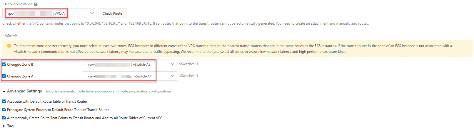
On the Basic Settings > Transit Router tab, find the transit router in the China (Chengdu) region and click Create Connection in the Actions column. Create VPC connections for both VPC-A and VPC-B.
For supported regions and zones, see Transit router editions.
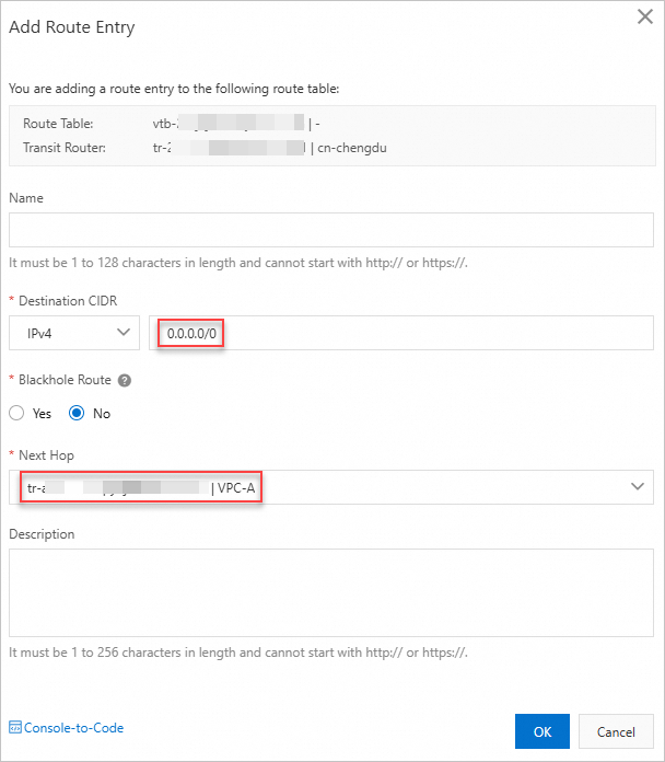
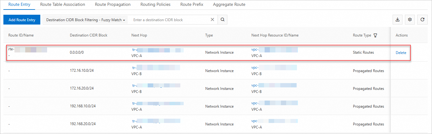
On the Transit Router Route Table tab, click Create Route Entry. Add a static route entry with destination 0.0.0.0/0 pointing to VPC-A Connection. This tells the transit router to forward all internet-bound IPv4 traffic from any attached spoke VPC to VPC-A, where the NAT gateway handles address translation. Without this route, spoke VPC traffic has no path to the internet.
Step 3: Add a route entry to VPC-B's route table
Add a 0.0.0.0/0 route in VPC-B's route table pointing to the transit router. Without this route, VPC-B's outbound traffic stays within the VPC and never reaches the transit router or NAT gateway.
Log on to the VPC console.
In the left-side navigation pane, click Route Tables.
On the Route Tables page, find the system route table of VPC-B and click its ID.
Click the Route Entry List > Custom Route tab, then click Add Route Entry.
In the Add Route Entry panel, configure the following parameters and click OK.
Parameter Value Name Enter a name for the route entry. Destination CIDR Block Select IPv4 CIDR Block and enter 0.0.0.0/0. Next Hop Type Select Transit Router. Forwarding Router Select VPC-B Connection.
The custom route entry appears on the Custom Route tab.
Step 4: Create an SNAT entry
Configure an SNAT entry on the NAT gateway. This determines which source resources can access the internet through the associated EIP.
On the Internet NAT Gateway page, find the NAT gateway and click Configure SNAT in the Actions column.
On the SNAT Management tab, click Create SNAT Entry.
On the Create SNAT Entry page, configure the following parameters and click OK.
Selecting multiple vSwitches or ECS instances/ENIs creates one SNAT entry per selection, all sharing the same EIP.
Parameter Description SNAT Entry Select VPC. This covers all ECS instances in VPC-A, plus instances in other VPCs or data centers connected through CEN with a 0.0.0.0/0 route pointing to VPC-A — including ECS2 in VPC-B. Use vSwitch or ECS/ENI for finer-grained control over which specific resources have internet access. Use Custom CIDR Block to specify any IP range across VPCs or on-premises environments. Select EIP Select the EIP to use for internet access.
Verify internet access
Log on to ECS1 and ECS2 through the Workbench console.
On each instance, run:
ping 223.5.5.5
Both ECS1 and ECS2 should receive responses, confirming that they can reach the internet through the shared Internet NAT gateway.
