By Ren Xijun (Zhejian).
This article explains the forwarding modes of Linux Virtual Server (LVS) and their working processes. It describes the causes, advantages, and disadvantages of the network packet forwarding principle and illustrates the merits and demerits taking into account the Alibaba Cloud Server Load Balancer (SLB).
Let's take a quick look at the various terms and acronyms used in the article.
cip:Client IP,客户端地址
vip:Virtual IP,LVS实例IP
rip:Real IP,后端RS地址
RS: Real Server 后端真正提供服务的机器
LB: Load Balance 负载均衡器
LVS: Linux Virtual Server
sip: source ip
dip: destination
The Linux Virtual Server helps in load balancing by eliminating single point of failure (SPOF). There are multiple ways to forward packets;
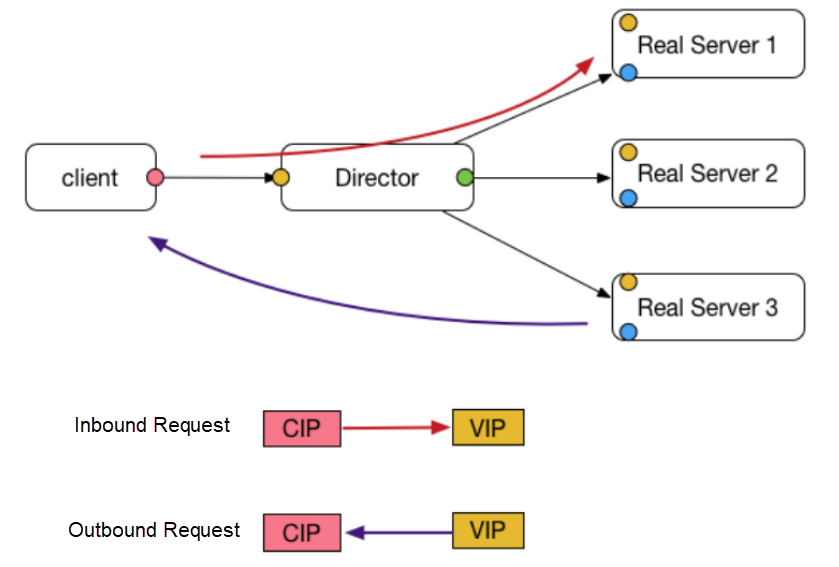
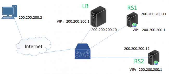
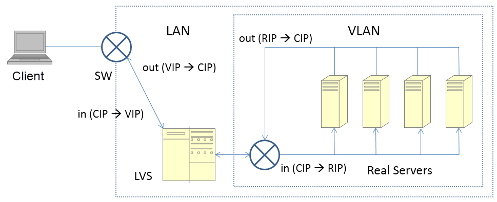
The preceding diagram illustrates how DR mode of LVS works. Now, let's consider the following example to understand the process.
Assume that the CIP is 200.200.200.2 and the VIP is 200.200.200.1.
As shown in the preceding process, after the request packet arrives at LVS, it just changes the destination MAC address of the packet, and forwards the response packet directly to the client.
Besides, note that multiple RSs and LVS share the same IP address but use different MAC addresses. L2 routes do not require IP addresses, and therefore, the RSs and LVS are on the same VLAN.
The RS configures the VIP on the LO loopback network interface controller (NIC) and adds the corresponding rule to the route, so that the operating system (OS) processes the packets received at step 4.
Advantages
Disadvantages
In DR mode, multiple RSs and LVS share the same VIP, and packets route between LVS and the RSs on the basis of the MAC address. Therefore, LVS and the RSs must belong to the same VLAN or L2 network.
Response packets do not pass through LVS. In most cases, request packets are small and response packets are large, which easily leads to a traffic bottleneck on the LVS. In addition, in DR mode, LVS only changes the MAC addresses of inbound packets.
RSs and LVS share the same VIP. Therefore, an RS correctly sets its SIP to the VIP while replying to a packet withoutLVS needing to change the SIP. In contrast, LVS changes the SIP during NAT and full NAT modes.
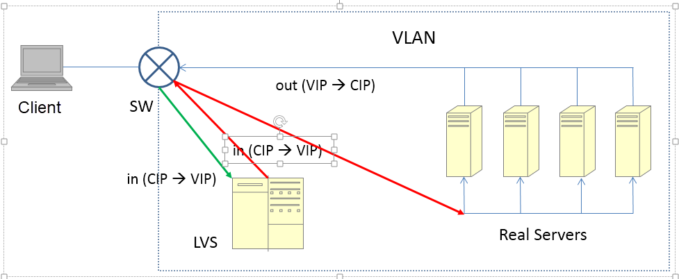
The above diagram shows the overall structure in DR mode. The green arrow indicates the inbound request packet, and the red arrow indicates the request packet with the changed MAC address.
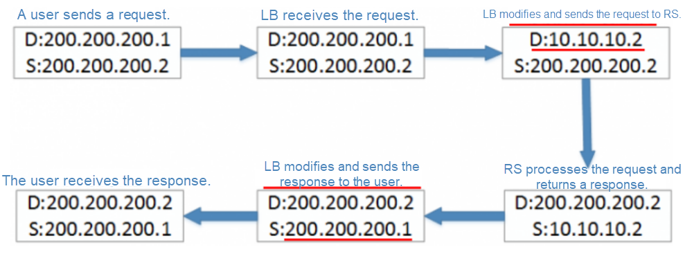
The following figure shows the structure in NAT mode.
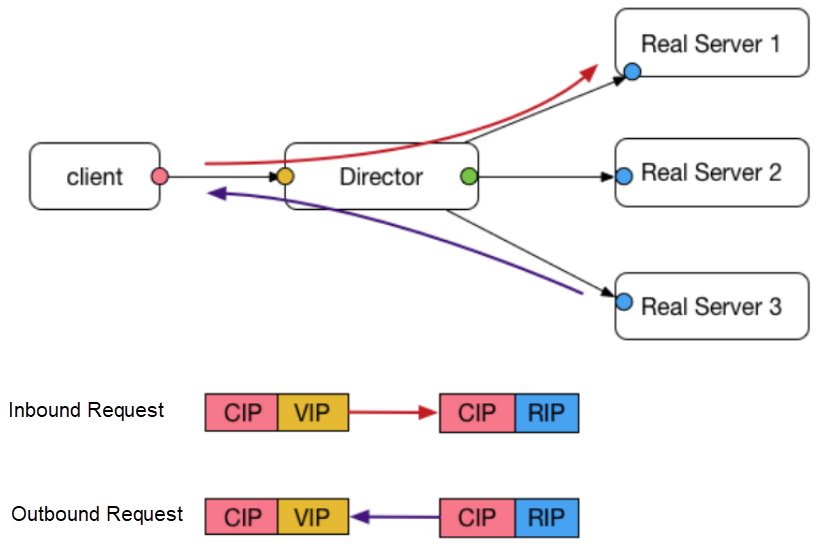
The general process for this mode is as follows.
Advantages
Disadvantages
The client recognizes the response packet only after LVS changes the SIP to the VIP. If the response packet's SIP is not the DIP (or VIP) of the request packet sent by the client, the connection is reset. Secondly, if LVS is not a gateway, the response packet is forwarded on other routes, because the DIP of the response packet is a CIP. In this case, LVS cannot change the SIP of the response packet.
Since, LVS only changes either the SIP or DIP of inbound and outbound packets, the full NAT mode emerges as a supplement. The greatest disadvantage of the NAT mode is that LVS and RSs must belong to the same VLAN, which limits the flexibility of deploying the LVS cluster and the RS cluster. NAT is basically impractical in commercial public cloud environments such as Alibaba Cloud.
This mode is similar to the NAT mode. The general process for this mode is as follows.
Advantages
Disadvantages
Taking cue from it's name, Full NAT LVS changes both, SIP and DIP of the inbound packet. Besides, the DIP of the response packet from the RS is the VIP (which is the CIP in NAT mode). Therefore, LVS and RSs can belong to different VLANs, provided that the L3 network between the VIP and RSs is available. In other words, LVS no longer needs to be a gateway, and LVS and RSs can be deployed in a more complex network environment.
Since the CIP changes in the Full NAT mode, the RS can only see the VIP of LVS. In Alibaba, the Option field of a TCP packet carries the CIP. On receiving the packet,RS usually deploys a self-defined TOA module to read the CIP from Option. In this case, the RS can see the CIP. However, this is not a universal open-source solution.
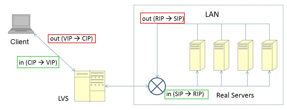
It is significant to note the IP address changes for the green inbound packet and the red outbound packet in the preceding figure.
So far, full NAT meets the same-VLAN requirement as in NAT mode, and is basically ready for the public cloud. However, this still does not resolve the problem that all inbound and outbound traffic passes through LVS, which implies that LVS needs to modify the inbound and outbound packets.
The concern here is to determine if there is a solution that doesn't restrict the network relationship between LVS and RSs prevailing in full NAT mode, and allows outbound traffic to bypass LVS as in DR mode.
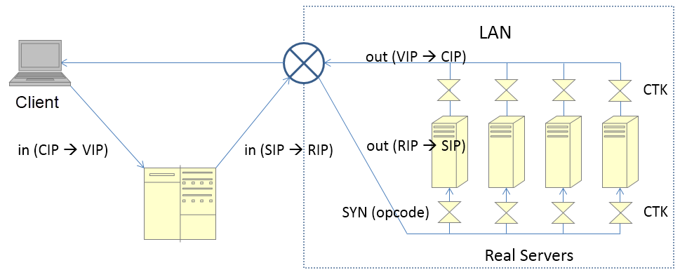
The Enhanced NAT (ENAT) mode is also known as triangle mode or DNAT mode. The general process for this mode is as follows:
Advantages
Disadvantages
In full NAT mode, LVS has to change the IP address in the response packet, and therefore the response packet must route back to LVS. However, in ENAT mode, the CTK module on the RS changes the IP in the response packet in advance.
The reason is the same as discussed earlier for the full NAT mode.
Finally, let's take a look at the less-used IP TUN mode. The general process for this mode is as follows:
Advantages
Disadvantages
Note: In DR mode, LVS changes the destination MAC address.
The MAC address remains unchanged in IP TUN mode. Therefore, cluster nodes may belong to different VLANs, given that the communication between the IP addresses of LVS and RSs is available. Broadcasts between LVS and RSs must be available in DR mode.
The response packet bypasses LVS. However, compared to the processing in DR mode, this mode allows additional encapsulation and decapsulation of the response packet.
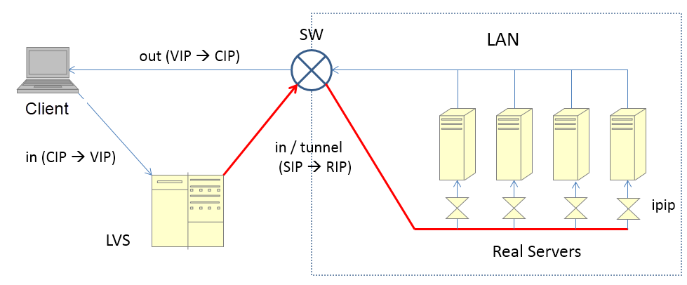
In the preceding figure, the red line indicates the re-encapsulated packet whereas the IPIP module indicates a kernel module of the OS.
This article throws light on various modes of Linux Virtual Server (LVS). It covers the fairly popular DR mode along with the lesser known IP TUN mode. Further, it also highlights the other three modes which are analogous and more popular. Hope you find the working process of each LVS mode explained in this article pragmatic.

2,593 posts | 791 followers
FollowAlibaba Clouder - December 31, 2020
Alibaba Developer - June 19, 2020
Alibaba Clouder - December 19, 2019
Alibaba Cloud Community - August 6, 2024
Alibaba Developer - June 22, 2020
oceanbaseworld - November 29, 2019

2,593 posts | 791 followers
Follow Server Load Balancer
Respond to sudden traffic spikes and minimize response time with Server Load Balancer
Learn More Alibaba Cloud Linux
Alibaba Cloud Linux is a free-to-use, native operating system that provides a stable, reliable, and high-performance environment for your applications.
Learn More Function Compute
Alibaba Cloud Function Compute is a fully-managed event-driven compute service. It allows you to focus on writing and uploading code without the need to manage infrastructure such as servers.
Learn More Simple Application Server
Cloud-based and lightweight servers that are easy to set up and manage
Learn MoreMore Posts by Alibaba Clouder