This topic describes how to create multiple IPsec-VPN connections over the Internet between a data center and a virtual private cloud (VPC). These connections form an Equal-Cost Multipath Routing (ECMP) link to load-balance traffic between the data center and the VPC.
Scenario

This topic uses the scenario in the preceding figure as an example. An enterprise has a data center in the China (Hangzhou) region and a VPC in the China (Shanghai) region. Applications are deployed on an Elastic Compute Service (ECS) instance in the VPC. The enterprise wants to use VPN Gateway to establish encrypted connections to Alibaba Cloud for communication with the VPC. The enterprise also wants to create multiple encrypted tunnels between the data center and the VPC. These tunnels form an ECMP link to load-balance traffic.
The enterprise can create multiple IPsec-VPN connections between the data center and Alibaba Cloud to establish encrypted connections. Then, the enterprise can use Cloud Enterprise Network (CEN) to connect the IPsec-VPN connections and the VPC. After the IPsec-VPN connections are added to the CEN instance, they automatically form an ECMP link. This enables communication and traffic load balancing between the data center and the VPC.
Network planning
Network features
The following network features are used in this scenario:
Establish IPsec-VPN connections between the data center and Alibaba Cloud over the Internet. In this scenario, the Gateway Type of the IPsec-VPN connections is set to Public.
The resource type attached to the IPsec-VPN connections is CEN. This allows the multiple IPsec-VPN connections to form an ECMP link.
Use Border Gateway Protocol (BGP) dynamic routing between the IPsec-VPN connections and the data center.
CIDR block planning
When you plan CIDR blocks, make sure that the CIDR blocks of the data center and the VPC do not overlap.
Resource | CIDR blocks and IP addresses |
VPC | Primary CIDR block: 10.0.0.0/16
|
IPsec-VPN connection | BGP configuration:
|
On-premises gateway device | Public IP addresses of the on-premises gateway devices:
|
BGP configuration for on-premises gateway devices:
| |
Data center | CIDR blocks to communicate with the VPC:
|
Preparations
Before you start, make sure that you have completed the following operations:
You have created a VPC in the China (Shanghai) region and deployed applications on an ECS instance in the VPC. For more information, see Create a VPC with an IPv4 CIDR block.
You have created a CEN instance and created an Enterprise Edition transit router in both the China (Hangzhou) and China (Shanghai) regions. For more information, see Create a CEN instance and Create a transit router.
ImportantWhen you create a transit router, you must configure a CIDR block for the transit router. Otherwise, IPsec connections cannot be associated with the transit router.
If you have created a transit router, you can configure a CIDR block for the transit router. For more information, see Transit router CIDR blocks.
You are familiar with the security group rules applied to the ECS instance in the VPC. Make sure that the security group rules allow the data center and the ECS instance to communicate with each other. For more information, see Query security group rules and Add a security group rule.
Configuration procedure
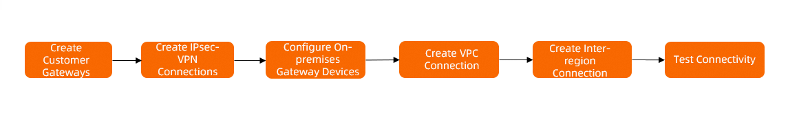
Step 1: Create customer gateways
Before you create an IPsec-VPN connection, you must create customer gateways to register the on-premises gateway devices with Alibaba Cloud.
Log on to the VPN Gateway console.
In the navigation pane on the left, choose .
In the top navigation bar, select the region where you want to create the customer gateways.
Select the region closest to your data center. In this topic, China (Hangzhou) is selected.
On the Customer Gateway page, click Create Customer Gateway.
In the Create Customer Gateway panel, configure the parameters and click OK.
Create three customer gateways in the China (Hangzhou) region with the following configurations. Keep the default values for other parameters. For more information, see Create and manage a customer gateway.
Parameter
Description
Customer Gateway 1
Customer Gateway 2
Customer Gateway 3
Name
Enter a name for the customer gateway.
Enter Customer-Gateway1.
Enter Customer-Gateway2.
Enter Customer-Gateway3.
IP Address
Enter the public IP address of the on-premises gateway device.
Enter the public IP address of on-premises gateway device 1: 11.XX.XX.1.
Enter the public IP address of on-premises gateway device 2: 11.XX.XX.2.
Enter the public IP address of on-premises gateway device 3: 11.XX.XX.3.
ASN
Enter the BGP Autonomous System Number (ASN) of the on-premises gateway device.
Enter 65530.
Step 2: Create IPsec-VPN connections
After you create the customer gateways, create IPsec-VPN connections on the Alibaba Cloud side.
Log on to the VPN Gateway console.
In the left navigation pane, choose .
On the IPsec Connections page, click Bind CEN.
On the Create IPsec-VPN Connection page, configure the IPsec-VPN connections and click OK.
Create three IPsec-VPN connections in the China (Hangzhou) region with the following configurations. Keep the default values for other parameters. For more information, see Manage a single-tunnel IPsec-VPN connection.
Parameter
Description
IPsec-VPN Connection 1
IPsec-VPN Connection 2
IPsec-VPN Connection 3
Name
Enter a name for the IPsec-VPN connection.
Enter IPsec-VPN Connection 1.
Enter IPsec-VPN Connection 2.
Enter IPsec-VPN Connection 3.
Region
Select the region of the transit router to attach.
The IPsec-VPN connection is created in the same region as the transit router.
Select China (Hangzhou).
Gateway Type
Select the network type of the IPsec-VPN connection.
Select Public.
Bind CEN
Select the account that owns the transit router.
Select Same Account.
CEN Instance ID
Select a CEN instance.
Select the CEN instance that you created in the "Preparations" section.
The system displays the instance ID and CIDR block of the transit router that is created by the CEN instance in the current region. The IPsec-VPN connection will be attached to the transit router.
Zone
Select a zone in which to deploy the IPsec-VPN connection. The zone must be supported by the transit router.
Select Hangzhou Zone H.
Routing Mode
Select a routing mode.
Select Destination Routing Mode.
NoteIf you use BGP dynamic routing, we recommend that you select Destination Routing Mode.
Effective Immediately
Select whether the configuration of the IPsec-VPN connection takes effect immediately. Valid values:
Yes. Start negotiations after the configuration is completed.
No. Start negotiations when inbound traffic is detected.
Select Yes.
Customer Gateway
Select the customer gateway to associate with the IPsec-VPN connection.
Select Customer-Gateway1.
Select Customer-Gateway2.
Select Customer-Gateway3.
Pre-Shared Key
Enter the authentication key for the IPsec-VPN connection. This key is used for identity authentication between the on-premises gateway device and the IPsec-VPN connection.
The key must be 1 to 100 characters in length. It can contain digits, letters, and the following special characters:
~`!@#$%^&*()_-+={}[]\|;:',.<>/?. The key cannot contain spaces.If you do not specify a pre-shared key, the system generates a random 16-character string. After the IPsec-VPN connection is created, you can click Edit for the tunnel to view the system-generated pre-shared key.
ImportantThe pre-shared key of the IPsec-VPN connection must be the same as the pre-shared key of the peer gateway device. Otherwise, the IPsec-VPN connection cannot be established.
Enter fddsFF123****.
Enter fddsFF456****.
Enter fddsFF789****.
Enable BGP
Select whether to enable BGP. BGP is disabled by default.
Enable BGP.
Local ASN
Enter the ASN for the IPsec-VPN connection.
Enter 65531.
Enter 65531.
Enter 65531.
Encryption Configuration
Specify the encryption configurations, such as the IKE and IPsec configurations.
Keep the default values for all parameters except for the following ones.
In the IKE Configurations section, set DH Group to group14.
In the IPsec Configurations section, set DH Group to group14.
NoteYou need to select encryption parameters based on the on-premises gateway device to ensure that the encryption configurations for the IPsec connection are the same as those for the on-premises gateway device.
BGP Configuration
Tunnel CIDR Block
Enter the CIDR block for the encrypted tunnel.
The tunnel CIDR block must be a /30 subnet within 169.254.0.0/16. It cannot be 169.254.0.0/30, 169.254.1.0/30, 169.254.2.0/30, 169.254.3.0/30, 169.254.4.0/30, 169.254.5.0/30, 169.254.6.0/30, or 169.254.169.252/30.
Enter 169.254.10.0/30.
Enter 169.254.11.0/30.
Enter 169.254.12.0/30.
Local BGP IP address
Enter the BGP IP address for the IPsec-VPN connection.
This address must be an IP address within the tunnel CIDR block.
Enter 169.254.10.1.
Enter 169.254.11.1.
Enter 169.254.12.1.
Advanced Configuration
Select whether to enable advanced configurations to automatically distribute and learn routes for the IPsec-VPN connection. Advanced configurations are enabled by default.
Keep the default value. All advanced configurations are enabled.
After the IPsec-VPN connections are created, the system automatically assigns a gateway IP address to each connection. This address is used to establish the connection with the on-premises gateway device. You can view the gateway IP address on the details page of the IPsec-VPN connection, as shown in the following figure.
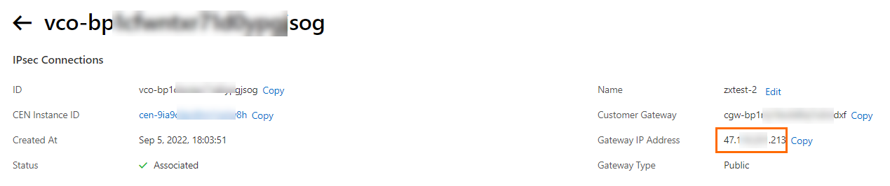
In this topic, the system assigns the gateway IP addresses shown in the following table to the three IPsec-VPN connections.
IPsec-VPN connection
Gateway IP address
IPsec-VPN connection 1
120.XX.XX.191
IPsec-VPN connection 2
47.XX.XX.213
IPsec-VPN connection 3
47.XX.XX.161
NoteThe system assigns a gateway IP address to an IPsec-VPN connection only after the connection is attached to a transit router.
Return to the IPsec-VPN connection page. Find the IPsec-VPN connections that you created. In the Actions column, choose Generate Peer Configuration.
Download the configurations for the three IPsec-VPN connections and save them to your computer. You will use these configurations to configure the on-premises gateway devices.
Step 3: Configure on-premises gateway devices
After you create the IPsec-VPN connections, use the downloaded configurations to add VPN and BGP configurations to the three on-premises gateway devices. This establishes the IPsec-VPN connections between the data center and Alibaba Cloud.
In this example, the software Adaptive Security Appliance (ASA) 9.19.1 is used to describe how to configure a Cisco firewall. The commands may vary with software versions. Consult the documentation or your vendor based on your actual environment during operations. For more information, see Configure local gateways.
The following content contains third-party product information, which is only for reference. Alibaba Cloud does not make guarantees or other forms of commitments for the performance and reliability of third-party products, or the potential impacts of operations performed by using these products.
Configure the on-premises gateway devices.
Configuration example for on-premises gateway device 1
Log on to the CLI of the Cisco firewall and enter the configuration mode.
ciscoasa> enable
Password: ********             # Enter the password for entering the enable mode.
ciscoasa# configure terminal   # Enter the configuration mode.
ciscoasa(config)#
View the interface configuration.
Make sure that the Cisco firewall has a complete interface configuration and that the interfaces are enabled. The following is an example of the interface configuration used in this topic.
# View the interface configuration of on-premises gateway device 1.
ciscoasa(config)# show running-config interface
!
interface GigabitEthernet0/0                # The interface that connects to the Internet.
 nameif outside1                            # The name of the GigabitEthernet0/0 interface.
 security-level 0
 ip address 11.XX.XX.1 255.255.255.255      # The public IP address configured for the GigabitEthernet0/0 interface.
!
interface GigabitEthernet0/1                # The interface that connects to the data center.
 nameif private                             # The name of the GigabitEthernet0/1 interface.
 security-level 100                         # Specify that the security level of the private interface connected to the data center is lower than that of the public interface.
 ip address 192.168.50.216 255.255.255.0    # The IP address configured for the GigabitEthernet0/1 interface.
!
Enable the IKEv2 feature for the public interface.
# Add the following configuration to on-premises gateway device 1.
crypto ikev2 enable outside1 # Enable the IKEv2 feature for the outside1 interface (public interface) of on-premises gateway device 1.
Create an IKEv2 policy. Specify the authentication algorithm, encryption algorithm, DH group, and SA lifetime for the IKE phase. These must be consistent with the configurations on the Alibaba Cloud side.
# Add the following configuration to on-premises gateway device 1.
crypto ikev2 policy 10
 encryption aes             # Specify the encryption algorithm.
 integrity sha              # Specify the authentication algorithm.
 group 14                   # Specify the DH group.
 prf sha                    # The prf must be consistent with integrity. On the Alibaba Cloud side, prf is consistent with the authentication algorithm by default.
 lifetime seconds 86400     # Specify the SA lifetime.
Create an IPsec proposal and profile. Specify the encryption algorithm, authentication algorithm, DH group, and SA lifetime for the IPsec phase on the Cisco firewall. These must be consistent with the configurations on the Alibaba Cloud side.
# Add the following configuration to on-premises gateway device 1.
crypto ipsec ikev2 ipsec-proposal ALIYUN-PROPOSAL    # Create an IPsec proposal.
 protocol esp encryption aes                         # Specify the encryption algorithm. The protocol is ESP. The Alibaba Cloud side uses the ESP protocol by default.
 protocol esp integrity sha-1                        # Specify the authentication algorithm. The protocol is ESP. The Alibaba Cloud side uses the ESP protocol by default.
crypto ipsec profile ALIYUN-PROFILE
 set ikev2 ipsec-proposal ALIYUN-PROPOSAL            # Create an IPsec profile and apply the created proposal.
 set ikev2 local-identity address                    # Specify that the local ID uses the IP address format, which must be consistent with the RemoteId format on the Alibaba Cloud side.
 set pfs group14                                     # Specify the PFS and DH group.
 set security-association lifetime seconds 86400     # Specify the time-based SA lifetime.
 set security-association lifetime kilobytes unlimited # Disable the traffic-based SA lifetime.
Create a tunnel group. Specify the pre-shared key for the tunnel. This must be consistent with the key on the Alibaba Cloud side.
# Add the following configuration to on-premises gateway device 1.
tunnel-group 120.XX.XX.191 type ipsec-l2l                  # Specify the tunnel encapsulation mode as l2l.
tunnel-group 120.XX.XX.191 ipsec-attributes
 ikev2 remote-authentication pre-shared-key fddsFF123****  # Specify the pre-shared key of the tunnel peer, which is the pre-shared key on the Alibaba Cloud side.
 ikev2 local-authentication pre-shared-key fddsFF123****   # Specify the local pre-shared key for the tunnel, which must be consistent with the key on the Alibaba Cloud side.
!
Create a tunnel interface.
# Add the following configuration to on-premises gateway device 1.
interface Tunnel1                                  # Create a tunnel interface.
 nameif ALIYUN1
 ip address 169.254.10.2 255.255.255.252           # Specify the IP address of the interface.
 tunnel source interface outside1                  # Specify the tunnel source address as the public interface GigabitEthernet0/0.
 tunnel destination 120.XX.XX.191                   # Specify the tunnel destination address as the public IP address of IPsec-VPN connection 1 on the Alibaba Cloud side.
 tunnel mode ipsec ipv4
 tunnel protection ipsec profile ALIYUN-PROFILE    # Apply the IPsec profile ALIYUN-PROFILE to the tunnel.
 no shutdown                                       # Enable the tunnel interface.
!
Configure routes.
# Add the following configuration to on-premises gateway device 1.
route outside1 120.XX.XX.191 255.255.255.255 192.XX.XX.172   # Configure a route to access the public IP address of IPsec-VPN connection 1 on the Alibaba Cloud side. The next hop is an external IP address.
route private 192.168.0.0 255.255.255.0 192.168.50.215         # Configure a route to the data center.
route private 192.168.1.0 255.255.255.0 192.168.50.215
route private 192.168.2.0 255.255.255.0 192.168.50.215

router bgp 65530
 address-family ipv4 unicast
  neighbor 169.254.10.1 remote-as 65531       # Specify the BGP peer, which is the BGP IP address of IPsec-VPN connection 1 on the Alibaba Cloud side.
  neighbor 169.254.10.1 ebgp-multihop 255
  neighbor 169.254.10.1 activate              # Activate the BGP peer.
  network 192.168.0.0 mask 255.255.255.0        # Advertise the CIDR block of the data center.
  network 192.168.1.0 mask 255.255.255.0
  network 192.168.2.0 mask 255.255.255.0
 exit-address-family
Configuration example for on-premises gateway device 2
Log on to the CLI of the Cisco firewall and enter the configuration mode.
ciscoasa> enable
Password: ********             # Enter the password for entering the enable mode.
ciscoasa# configure terminal   # Enter the configuration mode.
ciscoasa(config)#
View the interface configuration.
Make sure that the Cisco firewall has a complete interface configuration and that the interfaces are enabled. The following is an example of the interface configuration used in this topic.
# View the interface configuration of on-premises gateway device 2.
ciscoasa(config)# show running-config interface
!
interface GigabitEthernet0/0                # The interface that connects to the Internet.
 nameif outside1                            # The name of the GigabitEthernet0/0 interface.
 security-level 0
 ip address 11.XX.XX.2 255.255.255.255      # The public IP address configured for the GigabitEthernet0/0 interface.
!
interface GigabitEthernet0/1                # The interface that connects to the data center.
 nameif private                             # The name of the GigabitEthernet0/1 interface.
 security-level 100                         # Specify that the security level of the private interface connected to the data center is lower than that of the public interface.
 ip address 192.168.50.218 255.255.255.0    # The IP address configured for the GigabitEthernet0/1 interface.
!
Enable the IKEv2 feature for the public interface.
# Add the following configuration to on-premises gateway device 2.
crypto ikev2 enable outside1 # Enable the IKEv2 feature for the outside1 interface (public interface) of on-premises gateway device 2.
Create an IKEv2 policy. Specify the authentication algorithm, encryption algorithm, DH group, and SA lifetime for the IKE phase. These must be consistent with the configurations on the Alibaba Cloud side.
# Add the following configuration to on-premises gateway device 2.
crypto ikev2 policy 10
 encryption aes             # Specify the encryption algorithm.
 integrity sha              # Specify the authentication algorithm.
 group 14                   # Specify the DH group.
 prf sha                    # The prf must be consistent with integrity. On the Alibaba Cloud side, prf is consistent with the authentication algorithm by default.
 lifetime seconds 86400     # Specify the SA lifetime.
Create an IPsec proposal and profile. Specify the encryption algorithm, authentication algorithm, DH group, and SA lifetime for the IPsec phase on the Cisco firewall. These must be consistent with the configurations on the Alibaba Cloud side.
# Add the following configuration to on-premises gateway device 2.
crypto ipsec ikev2 ipsec-proposal ALIYUN-PROPOSAL    # Create an IPsec proposal.
 protocol esp encryption aes                         # Specify the encryption algorithm. The protocol is ESP. The Alibaba Cloud side uses the ESP protocol by default.
 protocol esp integrity sha-1                        # Specify the authentication algorithm. The protocol is ESP. The Alibaba Cloud side uses the ESP protocol by default.
crypto ipsec profile ALIYUN-PROFILE
 set ikev2 ipsec-proposal ALIYUN-PROPOSAL            # Create an IPsec profile and apply the created proposal.
 set ikev2 local-identity address                    # Specify that the local ID uses the IP address format, which must be consistent with the RemoteId format on the Alibaba Cloud side.
 set pfs group14                                     # Specify the PFS and DH group.
 set security-association lifetime seconds 86400     # Specify the time-based SA lifetime.
 set security-association lifetime kilobytes unlimited # Disable the traffic-based SA lifetime.
Create a tunnel group. Specify the pre-shared key for the tunnel. This must be consistent with the key on the Alibaba Cloud side.
# Add the following configuration to on-premises gateway device 2.
tunnel-group 47.XX.XX.213 type ipsec-l2l                  # Specify the tunnel encapsulation mode as l2l.
tunnel-group 47.XX.XX.213 ipsec-attributes
 ikev2 remote-authentication pre-shared-key fddsFF456****  # Specify the pre-shared key of the tunnel peer, which is the pre-shared key on the Alibaba Cloud side.
 ikev2 local-authentication pre-shared-key fddsFF456****   # Specify the local pre-shared key for the tunnel, which must be consistent with the key on the Alibaba Cloud side.
!
Create a tunnel interface.
# Add the following configuration to on-premises gateway device 2.
interface Tunnel1                                  # Create a tunnel interface.
 nameif ALIYUN1
 ip address 169.254.11.2 255.255.255.252           # Specify the IP address of the interface.
 tunnel source interface outside1                  # Specify the tunnel source address as the public interface GigabitEthernet0/0.
 tunnel destination 47.XX.XX.213                   # Specify the tunnel destination address as the public IP address of IPsec-VPN connection 2 on the Alibaba Cloud side.
 tunnel mode ipsec ipv4
 tunnel protection ipsec profile ALIYUN-PROFILE    # Apply the IPsec profile ALIYUN-PROFILE to the tunnel.
 no shutdown                                       # Enable the tunnel interface.
!
Configure routes.
# Add the following configuration to on-premises gateway device 2.
route outside1 47.XX.XX.213 255.255.255.255 192.XX.XX.173   # Configure a route to access the public IP address of IPsec-VPN connection 2 on the Alibaba Cloud side. The next hop is an external IP address.
route private 192.168.0.0 255.255.255.0 192.168.50.217         # Configure a route to the data center.
route private 192.168.1.0 255.255.255.0 192.168.50.217
route private 192.168.2.0 255.255.255.0 192.168.50.217

router bgp 65530
 address-family ipv4 unicast
  neighbor 169.254.11.1 remote-as 65531       # Specify the BGP peer, which is the BGP IP address of IPsec-VPN connection 2 on the Alibaba Cloud side.
  neighbor 169.254.11.1 ebgp-multihop 255
  neighbor 169.254.11.1 activate              # Activate the BGP peer.
  network 192.168.0.0 mask 255.255.255.0        # Advertise the CIDR block of the data center.
  network 192.168.1.0 mask 255.255.255.0
  network 192.168.2.0 mask 255.255.255.0
 exit-address-family
Configuration example for on-premises gateway device 3
Log on to the CLI of the Cisco firewall and enter the configuration mode.
ciscoasa> enable
Password: ********             # Enter the password for entering the enable mode.
ciscoasa# configure terminal   # Enter the configuration mode.
ciscoasa(config)#
View the interface configuration.
Make sure that the Cisco firewall has a complete interface configuration and that the interfaces are enabled. The following is an example of the interface configuration used in this topic.
# View the interface configuration of on-premises gateway device 3.
ciscoasa(config)# show running-config interface
!
interface GigabitEthernet0/0                # The interface that connects to the Internet.
 nameif outside1                            # The name of the GigabitEthernet0/0 interface.
 security-level 0
 ip address 11.XX.XX.3 255.255.255.255      # The public IP address configured for the GigabitEthernet0/0 interface.
!
interface GigabitEthernet0/1                # The interface that connects to the data center.
 nameif private                             # The name of the GigabitEthernet0/1 interface.
 security-level 100                         # Specify that the security level of the private interface connected to the data center is lower than that of the public interface.
 ip address 192.168.50.213 255.255.255.0    # The IP address configured for the GigabitEthernet0/1 interface.
!
Enable the IKEv2 feature for the public interface.
# Add the following configuration to on-premises gateway device 3.
crypto ikev2 enable outside1 # Enable the IKEv2 feature for the outside1 interface (public interface) of on-premises gateway device 3.
Create an IKEv2 policy. Specify the authentication algorithm, encryption algorithm, DH group, and SA lifetime for the IKE phase. These must be consistent with the configurations on the Alibaba Cloud side.
# Add the following configuration to on-premises gateway device 3.
crypto ikev2 policy 10
 encryption aes             # Specify the encryption algorithm.
 integrity sha              # Specify the authentication algorithm.
 group 14                   # Specify the DH group.
 prf sha                    # The prf must be consistent with integrity. On the Alibaba Cloud side, prf is consistent with the authentication algorithm by default.
 lifetime seconds 86400     # Specify the SA lifetime.
Create an IPsec proposal and profile. Specify the encryption algorithm, authentication algorithm, DH group, and SA lifetime for the IPsec phase on the Cisco firewall. These must be consistent with the configurations on the Alibaba Cloud side.
# Add the following configuration to on-premises gateway device 3.
crypto ipsec ikev2 ipsec-proposal ALIYUN-PROPOSAL    # Create an IPsec proposal.
 protocol esp encryption aes                         # Specify the encryption algorithm. The protocol is ESP. The Alibaba Cloud side uses the ESP protocol by default.
 protocol esp integrity sha-1                        # Specify the authentication algorithm. The protocol is ESP. The Alibaba Cloud side uses the ESP protocol by default.
crypto ipsec profile ALIYUN-PROFILE
 set ikev2 ipsec-proposal ALIYUN-PROPOSAL            # Create an IPsec profile and apply the created proposal.
 set ikev2 local-identity address                    # Specify that the local ID uses the IP address format, which must be consistent with the RemoteId format on the Alibaba Cloud side.
 set pfs group14                                     # Specify the PFS and DH group.
 set security-association lifetime seconds 86400     # Specify the time-based SA lifetime.
 set security-association lifetime kilobytes unlimited # Disable the traffic-based SA lifetime.
Create a tunnel group. Specify the pre-shared key for the tunnel. This must be consistent with the key on the Alibaba Cloud side.
# Add the following configuration to on-premises gateway device 3.
tunnel-group 47.XX.XX.161 type ipsec-l2l                  # Specify the tunnel encapsulation mode as l2l.
tunnel-group 47.XX.XX.161 ipsec-attributes
 ikev2 remote-authentication pre-shared-key fddsFF789****  # Specify the pre-shared key of the tunnel peer, which is the pre-shared key on the Alibaba Cloud side.
 ikev2 local-authentication pre-shared-key fddsFF789****   # Specify the local pre-shared key for the tunnel, which must be consistent with the key on the Alibaba Cloud side.
!
Create a tunnel interface.
# Add the following configuration to on-premises gateway device 3.
interface Tunnel1                                  # Create a tunnel interface.
 nameif ALIYUN1
 ip address 169.254.12.2 255.255.255.252           # Specify the IP address of the interface.
 tunnel source interface outside1                  # Specify the tunnel source address as the public interface GigabitEthernet0/0.
 tunnel destination 47.XX.XX.161                   # Specify the tunnel destination address as the public IP address of IPsec-VPN connection 3 on the Alibaba Cloud side.
 tunnel mode ipsec ipv4
 tunnel protection ipsec profile ALIYUN-PROFILE    # Apply the IPsec profile ALIYUN-PROFILE to the tunnel.
 no shutdown                                       # Enable the tunnel interface.
!
Configure routes.
# Add the following configuration to on-premises gateway device 3.
route outside1 47.XX.XX.161 255.255.255.255 192.XX.XX.174   # Configure a route to access the public IP address of IPsec-VPN connection 3 on the Alibaba Cloud side. The next hop is an external IP address.
route private 192.168.0.0 255.255.255.0 192.168.50.214         # Configure a route to the data center.
route private 192.168.1.0 255.255.255.0 192.168.50.214
route private 192.168.2.0 255.255.255.0 192.168.50.214

router bgp 65530
 address-family ipv4 unicast
  neighbor 169.254.12.1 remote-as 65531       # Specify the BGP peer, which is the BGP IP address of IPsec-VPN connection 3 on the Alibaba Cloud side.
  neighbor 169.254.12.1 ebgp-multihop 255
  neighbor 169.254.12.1 activate              # Activate the BGP peer.
  network 192.168.0.0 mask 255.255.255.0        # Advertise the CIDR block of the data center.
  network 192.168.1.0 mask 255.255.255.0
  network 192.168.2.0 mask 255.255.255.0
 exit-address-family
After you complete these configurations, IPsec-VPN connections are established between the data center and Alibaba Cloud. Routes from the data center are propagated to the BGP Route Table of the IPsec-VPN connections through BGP dynamic routing.
Add route configurations to your data center as needed based on your network environment. This ensures that traffic from clients in the data center to the VPC can be transmitted through all three on-premises gateway devices simultaneously. For specific commands, consult your device vendor.
Step 4: Create a VPC connection
The IPsec-VPN connections are automatically attached to the transit router after they are created. You must also create a VPC connection in the CEN console to attach the VPC to the transit router. This enables communication between the data center and the VPC.
Log on to the CEN console.
On the Instances page, click the ID of the CEN instance that you want to manage.
On the tab, find the transit router in the China (Shanghai) region. In the Actions column, click Create Connection.
On the Connection with Peer Network Instance page, configure the parameters and click OK.
Connect the VPC in the China (Shanghai) region to the transit router using the following configurations. Keep the default values for other parameters. For more information, see Create a VPC connection.
Parameter
Description
VPC connection
Instance Type
Select the network instance type.
Select Virtual Private Cloud (VPC).
Region
Select the region where the network instance is deployed.
Select China (Shanghai).
Transit Router
The system automatically displays the ID of the transit router in the current region.
Resource Owner ID
Select whether the network instance belongs to your current Alibaba Cloud account.
Select Your Account.
Billing Method
The billing method for the VPC connection. The default value is Pay-As-You-Go. For more information about the billing rules for transit routers, see Billing.
Attachment Name
Enter a name for the VPC connection.
Enter VPC-connection.
Network Instance
Select a network instance.
Select the VPC in the China (Shanghai) region.
VSwitch
Select vSwitches in the zones that the transit router supports.
If the transit router supports only one zone in the current region, you must select a vSwitch in that zone.
If the transit router supports multiple zones in the current region, you must select vSwitches in at least two different zones. This provides disaster recovery across zones for traffic between the VPC and the transit router.
Select a vSwitch in each zone to reduce traffic detours and transmission delays, and to improve performance.
Make sure that each selected vSwitch has an idle IP address. If the VPC does not have a vSwitch in the zones supported by the transit router, or if the vSwitches do not have idle IP addresses, you must create a vSwitch. For more information, see Create and manage vSwitches.
Select vSwitch 1 in Zone F and vSwitch 2 in Zone G.
Advanced Settings
Select whether to enable all advanced configuration options. By default, all advanced configuration options are enabled.
Keep the default configuration. All advanced configuration options are enabled.
Step 5: Create an inter-region connection
The transit router attached to the IPsec-VPN connections and the transit router attached to the VPC are in different regions. By default, the data center cannot communicate with the VPC. You must create an inter-region connection between the transit router in the China (Hangzhou) region and the transit router in the China (Shanghai) region to enable cross-region communication.
On the Instances page, find the destination CEN instance and click its ID.
On the tab, click Allocate Bandwidth for Inter-region Communication.
On the Connection with Peer Network Instance page, configure the inter-region connection and click OK.
Create an inter-region connection using the following configurations. Keep the default values for other parameters. For more information, see Create an inter-region connection.
Parameter
Description
Instance Type
Select Inter-region Connection.
Region
Select a region to connect.
Select China (Hangzhou).
Transit Router
The system automatically displays the ID of the transit router in the current region.
Attachment Name
Enter a name for the inter-region connection.
Enter Cross-Region-test.
Peer Region
Select the peer region to connect.
Select China (Shanghai).
Transit Router
The system automatically displays the ID of the transit router in the current region.
Bandwidth Allocation Mode
An inter-region connection supports the following bandwidth allocation modes:
Allocate from Bandwidth Plan: Bandwidth is allocated from a purchased bandwidth plan.
Pay-By-Data-Transfer: You are charged for the actual data transfer over the inter-region connection.
Select Pay-By-Data-Transfer.
Default Line Type
Use the default link type.
Bandwidth
Enter a bandwidth value for the inter-region connection. Unit: Mbit/s.
Advanced Settings
Keep the default configuration. All advanced configuration options are selected.
After you create the inter-region connection, the system automatically distributes and learns routes. The IPsec-VPN connections use BGP dynamic routing to propagate the VPC routes to the data center. They also propagate the data center routes to the transit router. This enables network communication between the data center and the VPC. For more information about the routes, see Routing description at the end of this topic.
Step 6: Test the connectivity
After you create the inter-region connection, the data center and the VPC can use the three IPsec-VPN connections to load-balance traffic. This section describes how to test network connectivity and verify that traffic is load-balanced across the connections.
Test the network connectivity.
Log on to the ECS instance in the VPC. For more information, see Connect to an ECS instance.
On the ECS instance, run the ping command to access a client in the data center.
ping <IP address of the client in the data center>If you receive a response message, a network connection is established between the data center and the VPC, and they can access each other's resources.
Verify traffic load balancing.
Continuously send access requests from multiple clients in the data center to the ECS instance. If you can view traffic monitoring data on the details pages of all three IPsec-VPN connections, the traffic between the data center and the VPC is load-balanced across the connections.
Log on to the VPN Gateway console.
In the top navigation bar, select the region where the IPsec-VPN connection is deployed.
In the navigation pane on the left, choose .
On the IPsec Connections page, find the destination IPsec-VPN connection and click its ID.
Go to the details page of the IPsec-VPN connection and view the traffic monitoring data on the Monitor tab.
Routing description
In this topic, the default route configurations are used when the IPsec-VPN connections, VPC connection, and inter-region connection are created. With the default configurations, CEN automatically distributes and learns routes to enable communication between the data center and the VPC. The default route configurations are described as follows:
IPsec-VPN connections
When you create an IPsec-VPN connection, you attach it directly to a transit router and enable all advanced configurations. The system automatically applies the following route configurations to the IPsec-VPN connection:
By default, the IPsec-VPN connection is associated with the default route table of the transit router. The transit router forwards traffic from the IPsec-VPN connection by looking up the default route table.
The destination-based routes that you add for the IPsec-VPN connection, or the on-premises routes learned by the IPsec-VPN connection through BGP dynamic routing, are automatically propagated to the default route table of the transit router.
The transit router automatically propagates other routes in its default route table to the BGP route table of the IPsec-VPN connection.
The IPsec-VPN connection automatically propagates the learned cloud routes to the data center through BGP dynamic routing.
VPC instances
If you enable all advanced configurations when creating a VPC connection, the system automatically applies the following route configurations to the VPC:
Associate with Default Route Table of Transit Router
After this feature is enabled, the VPC connection is automatically associated with the default route table of the transit router. The transit router forwards traffic from the VPC by looking up the default route table.
Propagate System Routes to Default Route Table of Transit Router
After this feature is enabled, the VPC propagates its system routes to the default route table of the transit router. This enables communication between network instances.
Automatically Create Route That Points to Transit Router and Add to All Route Tables of Current VPC
When this feature is enabled, the system automatically adds three routes (10.0.0.0/8, 172.16.0.0/12, and 192.168.0.0/16) to all route tables of the VPC. The next hop of these routes points to the VPC connection.
ImportantIf a route with the destination CIDR block 10.0.0.0/8, 172.16.0.0/12, or 192.168.0.0/16 already exists in the VPC's route table, the system cannot automatically add the route again. You must manually add a route that points to the VPC connection in the VPC route table to enable traffic between the VPC and the transit router.
You can click Initiate Route Check to check whether these routes exist in the network instance.
Inter-region connections
If you enable all advanced configurations when creating an inter-region connection, the system automatically applies the following route configurations to the inter-region connection:
Associate with Default Route Table of Transit Router
After this feature is enabled, the inter-region connection is automatically associated with the default route table of the transit router. The transit router uses the default route table to forward network traffic across regions.
Propagate System Routes to Default Route Table of Transit Router
After this feature is enabled, the inter-region connection is associated with the default route tables of the transit routers in the connected regions.
Automatically Advertise Routes to Peer Region
After this feature is enabled, the routes in the route table of the transit router in the current region are automatically advertised to the route table of the peer transit router for cross-region communication. The route tables of the transit routers refer to the route tables that are associated with the inter-region connection.
Route entries
The following tables show the route entries for the transit routers, IPsec-VPN connections, VPC, and on-premises gateway devices in this topic. You can view the route entries for the corresponding instances in the Alibaba Cloud console:
To view the route entries of a transit router, see Enterprise Edition.
To view the route entries of a VPC, see Create and manage a route table.
To view the route entries of an IPsec-VPN connection, go to its details page:
Log on to the VPN Gateway console.
In the top navigation bar, select the region where the IPsec-VPN connection is deployed.
In the navigation pane on the left, choose .
On the IPsec Connections page, find the destination IPsec-VPN connection and click its ID.
Go to the details page of the IPsec-VPN connection and view the route entries on the BGP Route Table tab.