Transit routers can enable multiple virtual private clouds (VPCs) to share an Internet NAT gateway. This enables the VPCs to access the Internet.
Background information
Cloud Enterprise Network (CEN) is a highly available network built on the global private network of Alibaba Cloud. CEN uses transit routers to enable network communication between VPCs in different regions and between VPCs and data centers.
Transit routers are the core network elements that forward network traffic across regions. Transit routers are region-specific and support custom routing policies. For a CEN instance, you can create only one transit router in each region. You can attach network instances to Enterprise Edition transit routers. After network instances are attached to an Enterprise Edition transit router, routes of the network instances are stored in the route tables of the transit router. The Enterprise Edition transit router forwards traffic of the network instances based on the routes in the route tables.
For more information about transit routers, see How transit routers work.
Example scenario
A company deployed two VPCs (VPC-A and VPC-B) in the China (Chengdu) region. In VPC-A, the company created vSwitch-A1 and vSwitch-A2, deployed an Internet NAT gateway in vSwitch-A1, and created an ECS1 instance in vSwitch-A2. In VPC-B, the company created vSwitch-B1 and vSwitch-B2, and deployed an ECS2 instance in vSwitch-B1. Due to business requirements, both VPC-A and VPC-B require Internet access.
In this case, the company can deploy an Internet NAT gateway in VPC-A and configure Source Network Address Translation (SNAT) rules for the NAT gateway. Then, the company can attach the VPCs to a transit router and create a route table on the transit router to enable the VPCs to access the Internet through the Internet NAT gateway.

Prerequisites
VPCs and vSwitches are created as described in the following table. For more information, see Create and manage a VPC.
VPC name
Region
vSwitch name
Zone and CIDR block
VPC-A
China (Chengdu)
vSwitch-A1
Chengdu Zone A, 192.168.10.0/24
vSwitch-A2
Chengdu Zone B, 192.168.20.0/24
VPC-B
vSwitch-B1
Chengdu Zone A, 172.16.10.0/24
vSwitch-B2
Chengdu Zone B, 172.16.20.0/24
An ECS instance (ECS1) is deployed in vSwitch-A2, and an ECS instance (ECS2) is deployed in vSwitch-B1. For information about how to create an instance, see Create an instance on the Custom Launch tab.
A Cloud Enterprise Network (CEN) instance is created. For more information, see Create a CEN instance.
An Enterprise Edition transit router is created in the region of the VPC. For more information, see Create a transit router.
Procedure
Step 1: Create an Internet NAT gateway
Log on to the NAT Gateway console.
On the Internet NAT Gateway page, click Create Internet NAT Gateway.
On the NAT Gateway page, configure the following parameters and click Buy Now.
Parameter
Description
Region
Select the region where you want to create the Internet NAT gateway.
Network And Zone
Select the VPC and vSwitch to which the NAT gateway belongs. After the NAT gateway is created, you cannot change the VPC or vSwitch.
Network Type
In this example, Internet NAT Gateway is selected.
Internet NAT Gateway: provides Network Address Translation capabilities and can be associated with EIPs to allow ECS instances to access the Internet, enabling communication between private and public networks.
VPC NAT Gateway: also provides Network Address Translation capabilities but cannot be associated with EIPs. It can only provide address translation within private networks for ECS instances, suitable for scenarios such as hiding internal addresses and avoiding address conflicts.
Elastic IP Address
In this example, Purchase And Associate EIP is selected.
Select Existing
EIP Instance: Select an EIP that is Not Associated With An Instance.
Purchase And Associate EIP: By default, a pay-by-traffic BGP (Multi-ISP) EIP is created. You can select a Bandwidth Peak based on your business requirements.
NoteIf you want to associate an EIP with a different line type or billing method, first apply for an EIP, and then Select An Existing EIP to associate.
Each EIP that you associate with a NAT gateway occupies a private IP address of the vSwitch to which the NAT gateway belongs. Make sure that the vSwitch has sufficient available private IP addresses. Otherwise, you cannot associate new EIPs with the NAT gateway.
Configure Later: The created NAT gateway will not have Internet access capabilities. You need to manually associate an EIP with the NAT gateway.
You can find the Internet NAT gateway on the Internet NAT Gateway page.

Step 2: Create VPC connections and configure routes
Create VPC-A Connection and VPC-B Connection in the transit router in the China (Chengdu) region, and configure routes for the transit router.
Log on to the CEN console, find the target CEN instance, and click the instance ID.
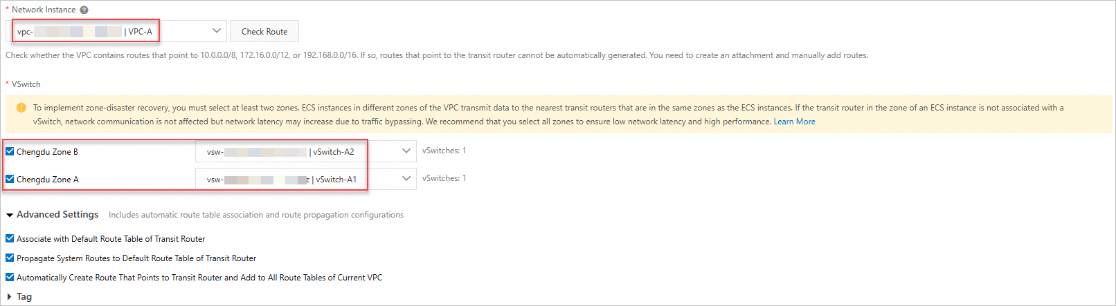
On the tab, find the transit router instance in the target region, and click Create Connection in the Actions column.
Create VPC connections for both VPC-A and VPC-B.
NoteFor information about regions and zones supported by Enterprise Edition transit routers, see Transit router editions.
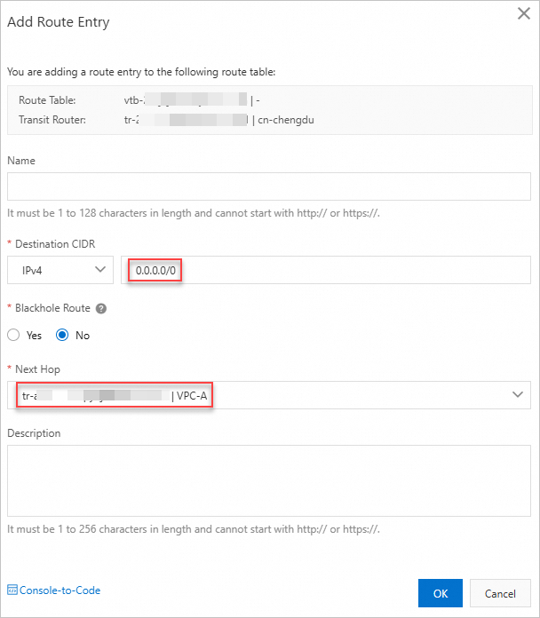
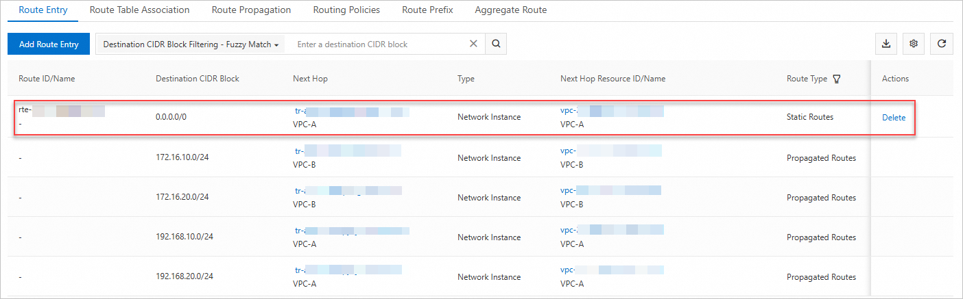
On the Transit Router Route Table tab, click Create Route Entry.
Add a route entry with destination 0.0.0.0/0 pointing to VPC-A to forward IPv4 traffic to VPC-A.
Step 3: Configure the VPC route table
Add a route entry with destination 0.0.0.0/0 pointing to the transit router in the route table to forward IPv4 traffic to the transit router.
Log on to the VPC console.
In the left-side navigation pane, click Route Tables.
On the Route Tables page, find the system route table of VPC-B and click its ID.
On the details page of the route table, click the tab, and then click Add Route Entry.
In the Add Route Entry panel, configure the following parameters and click OK.
Parameter
Description
Name
Enter a name for the route entry.
Destination CIDR Block
In this example, select IPv4 CIDR Block and set it to 0.0.0.0/0.
Next Hop Type
Select the next hop type.
In this example, select Transit Router.
Forwarding Router
In this example, select VPC-B Connection.
You can view the created route entry pointing to VPC-B Connection on the Custom Route tab.
Step 4: Create an SNAT entry
Configure SNAT entries on the NAT gateway to ensure that specified resources can access the Internet through the associated Elastic IP Address.
- On the Internet NAT Gateway page, find the NAT gateway that you want to manage and click Configure SNAT in the Actions column.
On the SNAT Management tab, click Create SNAT Entry.
On the Create SNAT Entry page, configure the following parameters and click OK.
Parameter
Description
SNAT Entry
In this example, VPC is selected. You can select an SNAT entry type based on your business requirements.
VPC: Suitable for scenarios where all ECS instances in the VPC, along with ECS instances in other VPCs or data centers that are connected through CEN or dedicated lines and have 0.0.0.0/0 routes pointing to this VPC, need to access the Internet through the same EIP.
VSwitch: Suitable for scenarios where fine-grained control over Internet access is required, allowing only specified vSwitches to have Internet access capabilities.
ECS/ENI: Suitable for scenarios where fine-grained control over Internet access is required, allowing only specified ECS instances or elastic network interfaces (ENIs) to have Internet access capabilities.
Custom CIDR Block: Suitable for scenarios where you need to flexibly specify any IP CIDR block to configure Internet access capabilities through NAT gateway. This can cover various network environments within a VPC, across VPCs, or across on-premises data centers, meeting the requirements of complex or customized network structures.
NoteIf you select multiple vSwitches or ECS instances/ENIs, multiple SNAT entries will be created using the same public IP address.
Select EIP
Select the EIP that is used to access the Internet.
Verification
Log on to ECS1 and ECS2 instances through the Workbench console.
Run the
ping 223.5.5.5command.The verification confirms that both ECS1 and ECS2 instances can successfully access the Internet.
