3FS is a high-performance distributed storage system developed by DeepSeek, specifically optimized for large-model AI training, big data analytics, and high-performance computing (HPC) workloads. 3FS combines modern SSD storage with RDMA network technology to overcome the performance bottlenecks of traditional networks. This topic describes how to deploy a 3FS cluster using Alibaba Cloud eRDMA, a cloud-native elastic RDMA network. The cluster provides low-latency, high-throughput data transmission to meet the high-performance demands of AI training and large-scale data analytics.
Deployment solution
This solution uses Alibaba Cloud's high-performance eRDMA network and the i4 instance family with local SSDs to build a 3FS cluster. AC2 provides a secure and reliable containerized access solution for the cluster.
Alibaba Cloud does not provide technical support for 3FS or guarantee the data integrity, data correctness, functionality, or performance of the 3FS software. If you encounter any issues, contact the 3FS community maintainers on GitHub.
eRDMA is an elastic Remote Direct Memory Access (RDMA) network developed by Alibaba Cloud for the cloud. eRDMA reuses virtual private clouds (VPCs) as the underlying link and uses a congestion control (CC) algorithm that is developed by Alibaba Cloud. eRDMA features high throughput and low latency based on RDMA supports. Compared with RDMA, eRDMA implements large-scale RDMA networking within seconds. eRDMA supports traditional HPC applications, AI applications, and Transmission Control Protocol/Internet Protocol (TCP/IP) applications.
For more information, see eRDMA.
The Alibaba Cloud i4 instance family with local SSDs uses PCIe Gen4 NVMe SSDs and the Cloud Infrastructure Processing Unit (CIPU) local disk virtualization architecture. This architecture results in almost zero degradation of SSD read and write bandwidth and provides I/O-level O&M and monitoring capabilities. For more information, see NVMe SSD local disks.
Alibaba Cloud AI Containers (AC2) is a collection of AI container images with built-in hardware acceleration libraries, AI runtimes, and AI frameworks — optimized for the Alibaba Cloud infrastructure to deliver better AI performance and experience across ECS, ACK, and ECI. AC2 images are free to use.
AC2 product images ensure end-to-end security and reliability throughout the production and release process. They are built with independently selected software and incorporate a CVE update policy and image security scanning mechanism to maximize the security of AI container images. For more information, see Alibaba Cloud AI Containers.
ImportantAll 3FS components mentioned in this topic are pre-built into the AC2 image. If you want to build them yourself, see the 3FS GitHub repository.
AC2 images are free of charge. You may be billed for other resources used alongside the images, such as vCPUs, memory, storage, public bandwidth, and snapshots.
To use AC2, you must first set up a Docker runtime environment. To enable eRDMA in a container, follow these instructions:
Use the Docker
--deviceoption to map the/dev/infiniband/rdma_cmand/dev/infiniband/uverbsXcharacter devices into the container. User mode programs can then bypass the kernel and access the eRDMA device directly./dev/infiniband/rdma_cm: Character device for eRDMA connection management, including creating and destroying connections and handling connection events./dev/infiniband/uverbsX: Character device for user space eRDMA operations, including opening the device, managing communication endpoints, and registering memory buffers.Note/dev/infiniband/uverbsX:Xis the device index number. Runls /dev/infiniband | grep uverbsto find the device name.
Key 3FS components
3FS consists of the following key components:
Metadata Service (Meta): A stateless service that handles file system metadata requests. It uses FoundationDB to perform atomic operations.
Storage Service (Storage): Runs on storage nodes. Data is stored in blocks on high-performance NVMe SSDs. It uses the Chain Replication with Apportioned Queries (CRAQ) protocol to manage replicas and provides write-all-read-any semantics.
Cluster manager (Mgmtd): Manages the cluster's configuration information and storage node status. It is responsible for electing a primary node and synchronizing updates to other components.
Client: 3FS provides two types of clients that balance compatibility and efficiency, making it an ideal storage interface for AI and big data workloads. One type uses Filesystem in Userspace (FUSE) for standardized access, and the other uses USRBIO for high-performance transport.
FUSE client: Mounts the storage cluster as a local directory through the user-space file system interface. It provides POSIX-compatible file operation interfaces such as
read,write, andmkdir, without requiring application code modifications.USRBIO high-performance client: Achieves microsecond-level latency and ultra-high throughput through a user-space I/O stack and RDMA, meeting the demands of AI and HPC.
All components communicate over an RDMA network, bypassing the kernel protocol stack to significantly reduce CPU load and network latency.
Deployment example
In this example, one g8i general-purpose instance (ecs.g8i.48xlarge) serves as a meta node to deploy meta, mgmtd, client, and monitoring services. Five i4 instances with local SSDs (ecs.i4.32xlarge) serve as storage nodes to provide high-performance NVMe SSD storage. All instances are in the same VPC and the same zone. eRDMA is configured on each node to enable elastic RDMA communication.
For simplicity, this example deploys the Meta, Mgmtd, client, and monitoring components on a single node. In a production environment, we recommend using a multi-node, distributed architecture to achieve service decoupling and resource isolation based on your business scale and high-availability requirements.

Step 1: Prepare the environment
Prepare the ECS instances for the 3FS nodes and configure eRDMA to enable elastic RDMA communication between them.
Create one ECS instance to serve as both the meta and client nodes, and create five ECS instances to serve as the storage nodes. All nodes must be able to communicate with each other over the internal network. Each node requires a public IP address to download AC2 image resources.
When you create all instances, note the following configurations. For other parameters, see Create an instance by using the wizard.
Region: This example uses the China (Hangzhou) region.
Instance Type: Select an instance type that supports eRDMA.
Meta node: ecs.g8i.48xlarge
Storage nodes: ecs.i4.32xlarge
Image: Select an Ubuntu 22 image that supports eRDMA.
eRDMA Interface: Enable the eRDMA interface for the instance's network interface to use the elastic RDMA communication mode.
ImportantThe IP addresses in this example are the primary private IP addresses of the primary network interface, which has eRDMA enabled.
In the Network configuration section, under Primary ENI, select Enable eRDMA.
Step 2: Deploy the meta node
Remotely connect to the meta node instance.
For more information, see Connect to a Linux instance by using Workbench.
Run the following commands on the instance to install the eRDMA driver.
curl -O http://mirrors.cloud.aliyuncs.com/erdma/env_setup.sh
sudo /bin/bash env_setup.sh > /var/log/erdma_install.log 2>&1
The installation script automatically installs the required software dependencies and the eRDMA driver. Wait for the script to finish.
Run the following command to verify that eRDMA is configured correctly.
ibv_devinfoThe following output indicates that eRDMA is enabled on the instance, meaning the eRDMA driver and network interface are configured correctly. The eRDMA driver installation may take some time. If an error is returned, see Verify the eRDMA configuration to resolve the error.
root@3fs-meta:~# ibv_devinfo
hca_id: erdma_0
	transport:			eRDMA (1)
	fw_ver:				0.2.0
	node_guid:			0216:3eff:fe08:cbeb
	sys_image_guid:			0216:3eff:fe08:cbeb
	vendor_id:			0x1ded
	vendor_part_id:			4223
	hw_ver:				0x0
	phys_port_cnt:			1
		port:	1
			state:			PORT_ACTIVE (4)
			max_mtu:		1024 (3)
			active_mtu:		1024 (3)
			sm_lid:			0
			port_lid:		0
			port_lmc:		0x00
			link_layer:		Ethernet
Run the following commands to set the RDMA connection establishment method to compatibility mode.
ImportantCurrently, for CPU-based instance types that support eRDMA, the default installation mode for the eRDMA kernel driver is Standard. This mode supports only the RDMA_CM connection establishment method.
eRDMA provides a compatibility mode (compat_mode) for applications in out-of-band (OOB) scenarios. In compatibility mode, an additional 16 TCP ports in the range of 30608 to 30623 are used.
sudo sh -c "echo 'options erdma compat_mode=Y' >> /etc/modprobe.d/erdma.conf"
sudo rmmod erdma
sudo modprobe erdma compat_mode=Y
Run the following commands to install Docker.
NoteTo use AC2, you must first set up a Docker runtime environment. Docker installation steps vary depending on the operating system. For more information, see Install and use Docker and Docker Compose on an ECS instance. This topic uses Ubuntu as an example.
apt update
apt install docker.io -y
After the installation is complete, run the following command to check the Docker version and verify that the installation was successful.
root@3fs-meta:~# docker -v
Docker version 26.1.3, build 26.1.3-0ubuntu1~22.04.1
Run the following command to deploy and start ClickHouse, which persists cluster runtime metrics such as node status, resource utilization, and I/O.
docker run -d --network=host --name clickhouse-server --ulimit nofile=262144:262144 ac2-registry.cn-hangzhou.cr.aliyuncs.com/ac2/clickhouse:25.3.1.2703-ubuntu22.04--net=host: Sets the container network mode tohost. Applications in the container share the host's network interfaces and configurations.--ulimit nofile: Sets the limit on the number of file descriptors for processes within the container (the maximum number of files a process can open simultaneously). This prevents system instability caused by a process consuming an excessive number of file handles.
Run the following command to deploy and start FoundationDB, which stores the cluster's transaction log configurations and data.
docker run -d --network=host --name fdb ac2-registry.cn-hangzhou.cr.aliyuncs.com/ac2/fdb:7.3.63-ubuntu22.04Run the following command to deploy and start the 3FS monitor, which collects and analyzes runtime metrics such as throughput, latency, and resource usage.
docker run -d --network=host --name monitor --ulimit memlock=-1 --privileged --device=/dev/infiniband/uverbs0 --device=/dev/infiniband/rdma_cm ac2-registry.cn-hangzhou.cr.aliyuncs.com/ac2/3fs:b71ffc55-fdb7.3.63-fuse3.16.2-ubuntu22.04 ./monitor.sh--ulimit memlock=-1: Setsmaxlockedmemorytounlimited, so non-root users can lock enough memory for eRDMA operations.--device=/dev/infiniband/uverbsXand--device=/dev/infiniband/rdma_cm: Expose the eRDMA user mode character devices to the container.View the character device name (the X in
uverbsX):ls /dev/infiniband | grep uverbs
Run the following command to deploy and start the 3FS cluster management service (mgmtd), which manages the storage nodes and resource allocation in the cluster.
docker run -d --network=host --name mgmtd --ulimit memlock=-1 --privileged --device=/dev/infiniband/uverbs0 --device=/dev/infiniband/rdma_cm --env FDB_CLUSTER=`docker exec fdb cat /etc/foundationdb/fdb.cluster` --env REMOTE_IP="172.16.20.172:10000" --env MGMTD_SERVER_ADDRESSES="RDMA://172.16.20.172:8000" ac2-registry.cn-hangzhou.cr.aliyuncs.com/ac2/3fs:b71ffc55-fdb7.3.63-fuse3.16.2-ubuntu22.04 ./mgmtd.sh--env REMOTE_IP: Set to the service address of the monitor. The IP address is the primary private IP address of the node where the monitor service is located (in this example, it is the same node as the meta node).--env MGMTD_SERVER_ADDRESSES: Set to the service address of mgmtd. The IP address is the primary private IP address of the node where the mgmtd service is started (in this example, it is the same node as the meta and monitor nodes).
Run the following command to deploy and start the 3FS metadata service (meta).
docker run -d --network=host --name meta --ulimit memlock=-1 --privileged --device=/dev/infiniband/uverbs0 --device=/dev/infiniband/rdma_cm --env FDB_CLUSTER=`docker exec fdb cat /etc/foundationdb/fdb.cluster` --env META_NODE_ID=100 --env REMOTE_IP="172.16.20.172:10000" --env MGMTD_SERVER_ADDRESSES="RDMA://172.16.20.172:8000" ac2-registry.cn-hangzhou.cr.aliyuncs.com/ac2/3fs:b71ffc55-fdb7.3.63-fuse3.16.2-ubuntu22.04 ./meta.sh--env META_NODE_ID: Set the sequential number of the meta node. In this example with one meta node, it is set to 100.--env REMOTE_IP: Set to the service address of the monitor. The IP address is the primary private IP address of the node where the monitor service is located (in this example, it is the same node as the meta node).--env MGMTD_SERVER_ADDRESSES: Set to the service address of mgmtd. The IP address is the primary private IP address of the node where the mgmtd service is started (in this example, it is the same node as the meta and monitor nodes).
Run the following command to view the running node services (Docker containers).
docker psroot@3fs-meta:~# docker ps CONTAINER ID IMAGE COMMAND CREATED STATUS PORTS NAMES 9bea3b0dc9bd ac2-registry.cn-hangzhou.cr.aliyuncs.com/ac2/3fs:b71ffc55-fdb7.3.63-fuse3.16.2-ubuntu22.04 "/bin/bash ./meta.sh" 2 minutes ago Up 2 minutes meta f7d8a2fc1513 ac2-registry.cn-hangzhou.cr.aliyuncs.com/ac2/3fs:b71ffc55-fdb7.3.63-fuse3.16.2-ubuntu22.04 "/bin/bash ./mgmtd.sh" 3 minutes ago Up 3 minutes mgmtd d98f5f6d5d46 ac2-registry.cn-hangzhou.cr.aliyuncs.com/ac2/fdb:7.3.63-ubuntu22.04 "/root/entrypoint.sh" 32 minutes ago Up 32 minutes fdb ef007f3e9ff8 ac2-registry.cn-hangzhou.cr.aliyuncs.com/ac2/3fs:b71ffc55-fdb7.3.63-fuse3.16.2-ubuntu22.04 "/bin/bash ./monitor…" 34 minutes ago Up 34 minutes monitor 9b369ddf877e ac2-registry.cn-hangzhou.cr.aliyuncs.com/ac2/clickhouse:25.3.1.2703-ubuntu22.04 "/root/entrypoint.sh" 34 minutes ago Up 34 minutes clickhouse-server
Step 3: Deploy storage nodes
Perform the following steps on each of the five storage nodes.
Remotely connect to the storage node instance.
For more information, see Connect to a Linux instance by using Workbench.
Run the following commands on the instance to install the eRDMA driver.
curl -O http://mirrors.cloud.aliyuncs.com/erdma/env_setup.sh
sudo /bin/bash env_setup.sh > /var/log/erdma_install.log 2>&1
The installation script automatically installs the required software dependencies and the eRDMA driver. Wait for the script to finish.
Run the following command to verify that eRDMA is configured correctly.
ibv_devinfoThe following output indicates that eRDMA is enabled on the instance, meaning the eRDMA driver and network interface are configured correctly. The eRDMA driver installation may take some time. If an error is returned, see Verify the eRDMA configuration to resolve the error.
root@3fs-storage-5:~# ibv_devinfo
hca_id: erdma_0
	transport:			eRDMA (1)
	fw_ver:				0.2.0
	node_guid:			0216:3eff:fe09:3bdb
	sys_image_guid:			0216:3eff:fe09:3bdb
	vendor_id:			0x1ded
	vendor_part_id:			4223
	hw_ver:				0x0
	phys_port_cnt:			1
		port:	1
			state:			PORT_ACTIVE (4)
			max_mtu:		1024 (3)
			active_mtu:		1024 (3)
			sm_lid:			0
			port_lid:		0
			port_lmc:		0x00
			link_layer:		Ethernet
Run the following commands to set the RDMA connection establishment method to compatibility mode.
ImportantCurrently, for CPU-based instance types that support eRDMA, the default installation mode for the eRDMA kernel driver is Standard. This mode supports only the RDMA_CM connection establishment method.
eRDMA provides a compatibility mode (compat_mode) for applications in out-of-band (OOB) scenarios. In compatibility mode, an additional 16 TCP ports in the range of 30608 to 30623 are used.
sudo sh -c "echo 'options erdma compat_mode=Y' >> /etc/modprobe.d/erdma.conf"
sudo rmmod erdma
sudo modprobe erdma compat_mode=Y
Run the following commands to format and mount the NVMe SSDs. In this example, eight local disks on the storage node are formatted with the XFS file system and then mounted. The XFS file system offers high performance and is suitable for large files.
mkdir -p /storage/data{0..7} for i in {0..7};do mkfs.xfs -L data${i} /dev/nvme${i}n1;mount -o noatime,nodiratime -L data${i} /storage/data${i};done; mkdir -p /storage/data{0..7}/3fsAfter mounting is complete, you can run the following command to view the partition status:
root@xxx:~# df -kh | grep nvme
/dev/nvme0n1      3.5T   25G  3.5T   1% /storage/data0
/dev/nvme1n1      3.5T   25G  3.5T   1% /storage/data1
/dev/nvme2n1      3.5T   25G  3.5T   1% /storage/data2
/dev/nvme3n1      3.5T   25G  3.5T   1% /storage/data3
/dev/nvme4n1      3.5T   25G  3.5T   1% /storage/data4
/dev/nvme5n1      3.5T   25G  3.5T   1% /storage/data5
/dev/nvme6n1      3.5T   25G  3.5T   1% /storage/data6
/dev/nvme7n1      3.5T   25G  3.5T   1% /storage/data7
Run the following commands to install Docker.
NoteTo use AC2, you must first set up a Docker runtime environment. Docker installation steps vary depending on the operating system. For more information, see Install and use Docker and Docker Compose on an ECS instance. This topic uses Ubuntu as an example.
apt update
apt install docker.io -y
After the installation is complete, run the following command to check the Docker version and verify that the installation was successful.
root@3fs-storage-5:~# docker -v
Docker version 26.1.3, build 26.1.3-0ubuntu1~22.04.1
Run the following command to start the storage service.
docker run -d --network=host --name storage --ulimit memlock=-1 --privileged -v /storage:/storage --device=/dev/infiniband/uverbs0 --device=/dev/infiniband/rdma_cm --env STORAGE_NODE_ID=10001 --env TARGET_PATHS="/storage/data0/3fs","/storage/data1/3fs","/storage/data2/3fs","/storage/data3/3fs","/storage/data4/3fs","/storage/data5/3fs","/storage/data6/3fs","/storage/data7/3fs" --env REMOTE_IP="172.16.20.172:10000" --env MGMTD_SERVER_ADDRESSES="RDMA://172.16.20.172:8000" ac2-registry.cn-hangzhou.cr.aliyuncs.com/ac2/3fs:b71ffc55-fdb7.3.63-fuse3.16.2-ubuntu22.04 ./storage.sh--device=/dev/infiniband/uverbsXand--device=/dev/infiniband/rdma_cm: Expose the eRDMA user mode character devices to the container.View the character device name (the X in
uverbsX):ls /dev/infiniband | grep uverbs--env STORAGE_NODE_ID: The sequential ID of the storage node. For five storage nodes, the IDs are 10001, 10002, 10003, 10004, and 10005. You must replace this value with the correct ID for each storage node.--env TARGET_PATHS: The storage directories for 3FS. In this example, these are the directories previously created on the local disks.--env REMOTE_IP: Set to the service address of the monitor. The IP address is the primary private IP address of the node where the monitor service is located (in this example, it is the same node as the meta node).--env MGMTD_SERVER_ADDRESSES: Set to the service address of mgmtd. The IP address is the primary private IP address of the node where the mgmtd service is started (in this example, it is the same node as the meta and monitor nodes).
Run the following command to view the running node services (Docker containers).
docker psroot@3fs-storage-5:~# docker ps CONTAINER ID IMAGE COMMAND CREATED STATUS PORTS NAMES 48335a374a26 ac2-registry.cn-hangzhou.cr.aliyuncs.com/ac2/3fs:b71ffc55-fdb7.3.63-fuse3.16.2-ubuntu22.04 "/bin/bash ./storage…" 3 minutes ago Up 3 minutes storage
Step 4: View connected storage nodes
Remotely connect to the meta node instance.
For more information, see Connect to a Linux instance by using Workbench.
Run the following command to view the status of the currently connected nodes.
docker exec -it meta /opt/3fs/bin/admin_cli -cfg /opt/3fs/etc/admin_cli.toml --config.mgmtd_client.mgmtd_server_addresses '["RDMA://172.16.20.172:8000"]' "list-nodes"Replace the IP address with the address of the mgmtd service that you configured.
root@3fs-meta:~# docker exec -it meta /opt/3fs/bin/admin_cli -cfg /opt/3fs/etc/admin_cli.toml --config.mgmtd_client.mgmtd_server_addresses '["RDMA://172.16.20.172:8000"]' "list-nodes" Id Type Status Hostname Pid Tags LastHeartbeatTime ConfigVersion ReleaseVersion 1 MGMTD PRIMARY_MGMTD 3fs-meta 19 [] N/A 1(UPTODATE) 250228-dev-1-999999-b71ffc55 100 META HEARTBEAT_CONNECTED 3fs-meta 40 [] 2025-04-14 07:12:19 1(UPTODATE) 250228-dev-1-999999-b71ffc55 10001 STORAGE HEARTBEAT_CONNECTED 3fs-storage-1 44 [] 2025-04-14 07:12:20 6(UPTODATE) 250228-dev-1-999999-b71ffc55 10002 STORAGE HEARTBEAT_CONNECTED 3fs-storage-2 44 [] 2025-04-14 07:12:21 6(UPTODATE) 250228-dev-1-999999-b71ffc55 10003 STORAGE HEARTBEAT_CONNECTED 3fs-storage-3 44 [] 2025-04-14 07:12:19 6(UPTODATE) 250228-dev-1-999999-b71ffc55 10004 STORAGE HEARTBEAT_CONNECTED 3fs-storage-4 44 [] 2025-04-14 07:12:19 6(UPTODATE) 250228-dev-1-999999-b71ffc55 10005 STORAGE HEARTBEAT_CONNECTED 3fs-storage-5 44 [] 2025-04-14 07:12:21 6(UPTODATE) 250228-dev-1-999999-b71ffc55admin_cliis a command-line tool for managing and maintaining 3FS. You can use it to perform operations such as cluster configuration, status monitoring, and troubleshooting. You can view detailed information by running the following command:docker exec -it meta /opt/3fs/bin/admin_cli -cfg /opt/3fs/etc/admin_cli.toml --config.mgmtd_client.mgmtd_server_addresses '["RDMA://172.16.20.172:8000"]' "help"
Step 5: Configure parameters
Configure storage node information, such as the number of replicas and the number of disks per storage node.
Remotely connect to the meta node instance.
For more information, see Connect to a Linux instance by using Workbench.
Run the following command to configure 3FS.
docker exec \
  --env STORAGE_NODE_NUM=5 \
  --env STORAGE_NODE_BEGIN=10001 \
  --env STORAGE_NODE_END=10005 \
  --env REPLICATION_FACTOR=3 \
  --env NUM_DISKS_PER_NODE=8 \
  --env MGMTD_SERVER_ADDRESSES="RDMA://172.16.20.172:8000" \
  meta \
  ./config_3fs.sh
--env STORAGE_NODE_NUM: The number of storage nodes. In this example, the value is 5.--env STORAGE_NODE_BEGIN: The starting sequential ID for storage nodes. In this example, the value is 10001.--env STORAGE_NODE_END: The ending sequential ID for storage nodes. In this example, the value is 10005.--env REPLICATION_FACTOR: The number of data replicas. The value 3 specifies that three replicas are used.--env NUM_DISKS_PER_NODE: The number of disks per storage node. In this example, the value is 8.--env MGMTD_SERVER_ADDRESSES: The address of the mgmtd service that you configured.--env NUM_TARGETS_PER_DISK: The expected number of storage targets to be created on a single physical disk. The default value is 12, which means each SSD is divided into 12 storage targets.--env MIN_TARGETS_PER_DISK: The minimum number of storage targets that must be guaranteed on a single physical disk. The default value is 12, which means each SSD must maintain at least 12 available storage targets.
The
config_3fs.shscript performs the following operations:The administrator user
rootis created and an authentication token is generated, which is then extracted and saved to/opt/3fs/etc/token.txtfor authenticating subsequent operations.A data distribution policy is generated based on incoming parameters such as
STORAGE_NODE_NUMandREPLICATION_FACTOR. A chained storage table is then generated based on this policy and uploaded to the mgmtd management server to complete the deployment of the target and chain structure for the storage nodes.
Run the following command to confirm that the chains were created successfully and are in a normal state.
docker exec -it meta /opt/3fs/bin/admin_cli -cfg /opt/3fs/etc/admin_cli.toml --config.mgmtd_client.mgmtd_server_addresses '["RDMA://172.16.20.172:8000"]' "list-chains"Replace the IP address with the address of the mgmtd service that you configured.
A successful command returns chain information, including columns such as ChainId, ReferencedBy, ChainVersion, Status, PreferredOrder, and Targets. A normal chain status is critical for the subsequent FIO tests.
Step 6: Configure the FUSE client
Configure the FUSE client on the meta node. The client mounts the remote storage, allowing you to perform file operations as if on a local file system.
Remotely connect to the meta node instance.
For more information, see Connect to a Linux instance by using Workbench.
Run the following command to obtain a token for secure client access.
docker exec meta cat /opt/3fs/etc/token.txtRun the following command to start the FUSE client.
docker run -d --network=host --name fuse --shm-size=200g --ulimit memlock=-1 --privileged \ --device=/dev/infiniband/uverbs0 --device=/dev/infiniband/rdma_cm \ --env REMOTE_IP="172.16.20.172:10000" \ --env MGMTD_SERVER_ADDRESSES="RDMA://172.16.20.172:8000" \ --env TOKEN=${token} \ ac2-registry.cn-hangzhou.cr.aliyuncs.com/ac2/3fs:b71ffc55-fdb7.3.63-fuse3.16.2-ubuntu22.04 \ ./fuse.sh--shm-size: Sets the size of the/dev/shmshared memory area inside the container.When testing with FUSE only, you can set --shm-size to a smaller value, such as 2g.
When testing with the USRBIO module, the test process needs to share the I/O buffer with the FUSE process through shared memory to achieve zero-copy. We recommend increasing
--shm-sizeto a value such as200g.
--device=/dev/infiniband/uverbsXand--device=/dev/infiniband/rdma_cm: Expose the eRDMA user mode character devices to the container.View the character device name (the X in
uverbsX):ls /dev/infiniband | grep uverbs--env REMOTE_IP: Set to the service address of the monitor. The IP address is the primary private IP address of the node where the monitor service is located (in this example, it is the same node as the meta node).--env MGMTD_SERVER_ADDRESSES: Set to the service address of mgmtd. The IP address is the primary private IP address of the node where the mgmtd service is started (in this example, it is the same node as the meta and monitor nodes).--env TOKEN: Set this to the token string that you obtained in the previous step.
Run the following command to view the running node services (Docker containers).
docker psroot@3fs-meta:~# docker ps CONTAINER ID IMAGE COMMAND CREATED STATUS PORTS NAMES 920f01360548 ac2-registry.cn-hangzhou.cr.aliyuncs.com/ac2/3fs:b71ffc55-fdb7.3.63-fuse3.16.2-ubuntu22.04 "/bin/bash ./fuse.sh" 3 minutes ago Up 3 minutes fuse 9bea3b0dc9bd ac2-registry.cn-hangzhou.cr.aliyuncs.com/ac2/3fs:b71ffc55-fdb7.3.63-fuse3.16.2-ubuntu22.04 "/bin/bash ./meta.sh" About an hour ago Up About an hour meta f7d8a2fc1513 ac2-registry.cn-hangzhou.cr.aliyuncs.com/ac2/3fs:b71ffc55-fdb7.3.63-fuse3.16.2-ubuntu22.04 "/bin/bash ./mgmtd.sh" About an hour ago Up About an hour mgmtd d98f5f6d5d46 ac2-registry.cn-hangzhou.cr.aliyuncs.com/ac2/fdb:7.3.63-ubuntu22.04 "/root/entrypoint.sh" About an hour ago Up About an hour fdb ef007f3e9ff8 ac2-registry.cn-hangzhou.cr.aliyuncs.com/ac2/3fs:b71ffc55-fdb7.3.63-fuse3.16.2-ubuntu22.04 "/bin/bash ./monitor…" 2 hours ago Up 2 hours monitor 9b369ddf877e ac2-registry.cn-hangzhou.cr.aliyuncs.com/ac2/clickhouse:25.3.1.2703-ubuntu22.04 "/root/entrypoint.sh" 2 hours ago Up 2 hours clickhouse-serverRun the following command to check the file system mount and disk usage in the FUSE container.
docker exec fuse df -hT | grep 3fsroot@3fs-meta:~# docker exec fuse df -hT | grep 3fs hf3fs.stage fuse.hf3fs 140T 18T 123T 13% /3fs
FIO performance tests
After deployment, the FUSE node's Docker container provides a high-performance distributed file system based on 3FS that uses eRDMA for inter-node communication.
Flexible I/O Tester (FIO) is an open-source storage performance benchmark tool designed to evaluate the I/O capabilities of storage systems such as hard drives, SSDs, and distributed file systems. Its core value lies in its ability to simulate real-world workload models and accurately quantify key performance indicators such as throughput, IOPS, and latency through highly configurable test parameters.
The following sections describe how to use FIO to test the performance of the deployed 3FS file system.
USRBIO
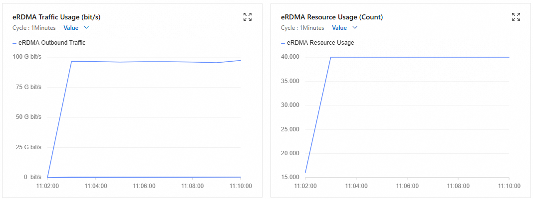
In a FUSE container, 100 jobs are started to simulate a workload scenario of high-concurrency sequential writes to large files, testing the peak performance of 3fs on an eRDMA network. The hf3fs_usrbio.so engine enables user-space RDMA communication. Compared with kernel-space FUSE, it implements zero-copy RDMA optimization, resulting in a significant performance improvement.
Remotely connect to the meta node instance.
For more information, see Connect to a Linux instance by using Workbench.
Run the following command to start the test.
docker exec -it fuse \ fio -numjobs=100 -fallocate=none \ -ioengine=external:/usr/lib/hf3fs_usrbio.so \ -direct=1 \ -rw=write \ -bs=4MB \ --group_reporting \ -filesize=500MB \ --nrfiles=100 \ -iodepth=1 \ -name=/3fs/test \ -mountpoint=/3fs \ -ior_depth=1-numjobs=100: Starts 100 concurrent jobs (threads/processes) to simulate a multi-threaded concurrent write scenario, testing the system's throughput and lock contention under high concurrency.-ioengine=external:/usr/lib/hf3fs_usrbio.so: Uses the dedicated 3FS RDMA engine.-direct=1: Enables direct I/O, which bypasses the operating system cache.-rw=write: Sets the test mode to sequential write to evaluate continuous write bandwidth.-bs=4M: Sets the block size to 4 MB to simulate large-block data write scenarios, such as video streaming or batch data processing.--group_reporting: Merges the results of all jobs into a summary output, making it easier to view the overall performance rather than individual job data.-filesize=500MB: Each job writes 500 MB of data. The total data volume is 500 MB × 100 jobs = 50 GB.--nrfiles=100: Creates a total of 100 files (one file per job) to test concurrent write performance for multiple files.-iodepth=1: The I/O queue depth for each job is 1, which means each job submits only one I/O request at a time.-mountpoint=/3fs: Specifies the 3FS file system mount path as the/3fsdirectory.-ior_depth=1: Specifies the RDMA send queue depth. A value of 1 indicates synchronous I/O mode.
During the test, you can view the instance's eRDMA traffic on the monitoring page for the FUSE client's node. For more information, see View monitoring information of network interfaces.
Wait for the test to complete and view the results.
jobs: 16 (f=227): [w(16)] [100.0% done] [0KB/11.2GiB/0KB /s] [0/2871/0 iops] [eta 00m:00s]
write: IOPS=2621, BW=10.2GiB/s (11.0GB/s)(153GiB/15002msec); 0 zone resets
  slat (usec): min=69, max=3031, avg=382.71, stdev=164.92, samples=78316
  clat (msec): min=6, max=2023, avg=93.97, stdev=32.35, samples=78194
   lat (msec): min=7, max=2023, avg=94.35, stdev=32.28, samples=78194
  clat percentiles (msec):
   |  1.00th=[   59],  5.00th=[   68], 10.00th=[   73], 20.00th=[   79],
   | 30.00th=[   83], 40.00th=[   87], 50.00th=[   91], 60.00th=[   95],
   | 70.00th=[  100], 80.00th=[  106], 90.00th=[  118], 95.00th=[  132],
   | 99.00th=[  180], 99.50th=[  203], 99.90th=[  338], 99.95th=[  502],
   | 99.99th=[ 1854]
  bw (  MiB/s): min=7406.80, max=12116.67, per=100.00%, avg=10551.79, stdev=52.38, samples=464
  iops        : min= 1846, max= 3026, avg=2633.48, stdev=13.07, samples=464
  lat (msec)  : 10=0.01%, 20=0.03%, 50=0.40%, 100=70.32%, 250=29.02%
  lat (msec)  : 500=0.17%, 750=0.02%, 1000=0.01%, 2000=0.02%, >=2000=0.01%
  cpu         : usr=1.21%, sys=0.02%, ctx=64898, majf=0, minf=8190
The core metrics are as follows:
Throughput:
IOPS=2621: 2,621 4-MB write operations per second.BW=10.2GiB/s (11.0GB/s): The actual test bandwidth reached 10.2 GiB/s.
System resource consumption:
cpu: usr=1.21%, sys=0.02%: Ultra-low CPU usage, highlighting the advantage of eRDMA.
POSIX
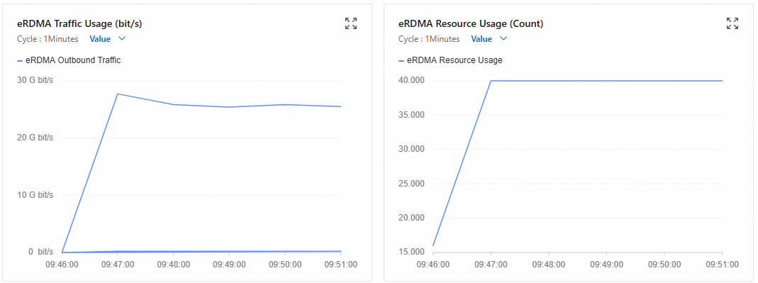
This test uses the Linux asynchronous I/O engine in the FUSE container to simulate concurrent writes with two jobs. It uses a 4 MB block size to test sequential write bandwidth and runs for 5 minutes to measure stability.
Remotely connect to the meta node instance.
For more information, see Connect to a Linux instance by using Workbench.
Run the following command to start the test.
docker exec -it fuse \ fio -numjobs=2 -fallocate=none \ -iodepth=2 \ -ioengine=libaio \ -direct=1 \ -rw=write \ -bs=4M \ --group_reporting \ -size=100M \ -time_based \ -runtime=300 \ -name=2depth_128file_4M_direct_write_bw \ -directory=/3fs-numjobs=2: Starts two concurrent jobs (threads/processes) to simulate a multi-threaded concurrent write scenario, testing the system's throughput and lock contention.-iodepth=2: The I/O queue depth for each job is 2, which means each job submits two I/O requests simultaneously.-ioengine=libaio: Uses the Linux asynchronous I/O engine (libaio), which supports non-blocking I/O.-direct=1: Enables direct I/O, which bypasses the operating system cache.-rw=write: Sets the test mode to sequential write to evaluate continuous write bandwidth.-bs=4M: Sets the block size to 4 MB to simulate large-block data write scenarios, such as video streaming or batch data processing.--group_reporting: Merges the results of all jobs into a summary output, making it easier to view the overall performance rather than individual job data.-size=100M: Each job writes 100 MB of data (total data volume = 100 MB × 2 jobs = 200 MB).-time_basedand-runtime=300: Set the run time to 300 seconds (5 minutes). The test runs for the full duration to measure long-term write stability, even if the initial data write completes early.-directory=/3fs: Specifies the 3FS file system mount path as the/3fsdirectory.
During the test, you can view the instance's eRDMA traffic on the monitoring page for the FUSE client's node. For more information, see View monitoring information of network interfaces.
Wait for the test to complete and view the results.
jobs: 16 (f=227): [w(16)] [100.0% done] [0KB/3016MiB/0KB /s] [0/753/0 iops] [eta 00m:00s]
write: IOPS=715, BW=2862MiB/s (3001MB/s)(41.9GiB/15005msec); 0 zone resets
  slat (usec): min=77, max=4938, avg=390.86, stdev=142.53
  clat (msec): min=15, max=2605, avg=344.39, stdev=117.27
   lat (msec): min=16, max=2605, avg=344.78, stdev=117.23
  clat percentiles (msec):
   |  1.00th=[  182],  5.00th=[  218], 10.00th=[  239], 20.00th=[  268],
   | 30.00th=[  292], 40.00th=[  313], 50.00th=[  334], 60.00th=[  355],
   | 70.00th=[  380], 80.00th=[  414], 90.00th=[  464], 95.00th=[  510],
   | 99.00th=[  659], 99.50th=[  751], 99.90th=[ 1586], 99.95th=[ 1904],
   | 99.99th=[ 2601]
  bw (  MiB/s): min= 1219.31, max=3419.18, per=100.00%, avg=2901.15, stdev=24.14
  iops        : min=  304, max=  854, avg= 724.37, stdev= 6.02
  lat (msec)  : 20=0.01%, 50=0.02%, 100=0.10%, 250=13.41%, 500=80.87%
  lat (msec)  : 750=5.10%, 1000=0.31%, 2000=0.15%, >=2000=0.03%
  cpu         : usr=18.66%, sys=2.55%, ctx=64898, majf=0, minf=8190
The core metrics are as follows:
Throughput:
IOPS=715: 715 4-MB write operations per second (715 × 4 MB ≈ 2,860 MB/s).BW=2862MiB/s (3001MB/s): The actual bandwidth reached approximately 2.8 GiB/s.
System resource consumption:
cpu: usr=18.66%, sys=2.55%: High user-space CPU consumption, caused by the overhead of the libaio engine.