Data Integration supports real-time synchronization from a single Hologres table to another Hologres table. When the task starts, it creates a destination table based on the source table's schema, runs a full initialization to copy existing data, then continuously applies incremental changes — inserts, updates, and deletes — as they arrive.
Limits
Not all Hologres tables and data types are supported. Check the following before you configure the task.
| Capability | Supported |
|---|---|
| Hologres instance version V2.1 or later (source) | Required |
| Single table synchronization | Yes |
| Partitioned table incremental synchronization | No — use a full offline sync instead |
| DDL change synchronization | No |
Supported incremental data types:
INTEGER, BIGINT, TEXT, CHAR(n), VARCHAR(n), REAL, JSON, SERIAL, OID, INT4[], INT8[], FLOAT8[], BOOLEAN[], TEXT[]
Prerequisites
Before you begin, make sure you have:
-
A serverless resource group purchased
-
Two Hologres data sources added to DataWorks — one as the source, one as the destination. For setup instructions, see Data source configuration
-
Network connectivity established between the serverless resource group and both data sources. See Overview of network connectivity solutions
-
Binary logging enabled on the source Hologres table. See Subscribe to Hologres binlogs
Create and run a synchronization task
Step 1: Select synchronization type
-
Log on to the DataWorks console. In the top navigation bar, select your region. In the left-side navigation pane, choose Data Integration > Data Integration, then select your workspace and click Go to Data Integration.
-
In the left-side navigation pane, click Synchronization Task. At the top of the page, select source and destination types and click Create Synchronization Task.
-
Configure the following basic settings:
Parameter Value Source And Destination Select Hologresfor both source and destinationNew Node Name Enter a name for the task Synchronization Method Single table real-time synchronizationSynchronization Mode Full initialization
Step 2: Configure network settings and a resource group
-
In the Network and Resource Configuration section, select a resource group and configure the Task Resource Usage parameter.
-
Select the Hologres data sources — one in the Source section and one in the Destination section — then click Test Connectivity.
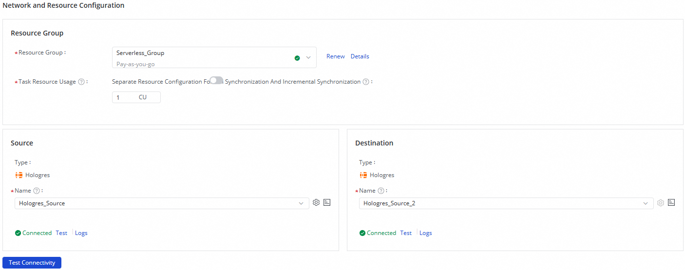
-
Click Next.
Step 3: Configure the data synchronization link
Configure the source
In the wizard at the top of the configuration page, click Hologres to open the source configuration.

-
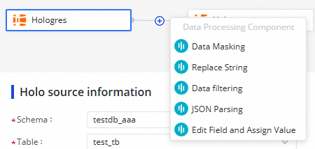
In the Holo source information section, set the Schema and Table parameters to identify the source table.
-
Click Data Sampling in the upper-right corner of the section. In the Preview Data Output dialog box, set Sampled Data Records and click Start Collection to pull a sample from the source table. The sampled data is used for preview and testing in subsequent steps.
Configure a data processing node (optional)
Click the ![]() icon to add one or more data processing methods between the source and destination. Available methods:
icon to add one or more data processing methods between the source and destination. Available methods:
-
[Data Masking](https://www.alibabacloud.com/help/en/document_detail/2836997.html)
-
[Replace String](https://www.alibabacloud.com/help/en/document_detail/2836998.html)
-
[Data filtering](https://www.alibabacloud.com/help/en/document_detail/2836999.html)
-
[JSON Parsing](https://www.alibabacloud.com/help/en/document_detail/2837000.html)
-
[Edit Field and Assign Value](https://www.alibabacloud.com/help/en/document_detail/2837001.html)
Arrange the methods in the order you want them applied. When the task runs, data passes through them in that sequence.
After configuring a processing node, click Preview Data Output in the upper-right corner to verify the output. In the dialog box, click Re-obtain Output of Ancestor Node to reprocess the sampled data and preview the result.
Complete data sampling for the source before previewing data processing output.
Configure the destination
In the wizard at the top of the configuration page, click Hologres to open the destination configuration.

-
In the Destination Information section, set the Schema and Destination Table parameters:
-
Create tables automatically — the system creates a destination table with the same name as the source table. You can rename it manually.
-
Use Existing Table — select an existing table from the Table Name drop-down list.
-
-
(Optional) If you selected Create tables automatically, click Edit Table Schema to adjust the schema of the table before it is created. Click Re-generate Table Schema Based on Output Column of Ancestor Node to rebuild the schema from upstream output. Select a column and mark it as the primary key.
ImportantThe destination table must have a primary key. The configuration cannot be saved without one.
-
Set Job Type and Write Conflict Policy based on your use case: Job Type controls how changes from the source are written to the destination: Write Conflict Policy controls what happens when a write conflicts with an existing record:
Job type How it works When to use Replay (Replay Operation Log to Restore Data) Replays INSERT, UPDATE, and DELETE operations on the destination Keeping the destination in sync with the source (for example, disaster recovery or read replicas) Insert (Archived Storage) Inserts all incoming records into the destination without DELETE or UPDATE Building an append-only audit trail or event log Policy Behavior When to use Cover (Overwrite) Overwrites the existing record Most sync scenarios — keeps the destination current Ignore (Ignore) Keeps the existing record unchanged Preserving manually written data in the destination -
Review field mappings. The system maps source and destination fields automatically using the Map Fields with Same Name principle. Adjust mappings as needed:
-
One source field can map to multiple destination fields.
-
Multiple source fields cannot map to the same destination field.
-
Source fields with no mapping are not synchronized.
-
Step 4: Configure alert rules
Set up alert rules to get notified if the synchronization task falls behind or fails.
-
In the upper-right corner of the page, click Configure Alert Rule to open the Alert Rule Configurations for Real-time Synchronization Subnode panel.
-
Click Add Alert Rule and configure the rule parameters.
Alert rules configured here apply to the real-time synchronization subtask generated by this task. After the task is created, go to the Real-time Synchronization Task page to modify them. For details, see Run and manage real-time synchronization tasks.
-
Enable or disable alert rules as needed. Assign different alert recipients by severity level.
Step 5: Configure advanced parameters
-
In the upper-right corner of the configuration page, click Configure Advanced Parameters.
-
In the Configure Advanced Parameters panel, change the values of any parameters you need to adjust.
Understand what each parameter does before changing its value to avoid unexpected errors or data quality issues.
Step 6: Configure resource groups
Click Configure Resource Group in the upper-right corner to view or change the resource groups assigned to this task.
Step 7: Run a simulated run
Before running the task, use Perform Simulated Running to test the end-to-end flow using sampled data.
-
In the upper-right corner of the configuration page, click Perform Simulated Running.
-
In the dialog box, set the Start At and Sampled Data Records parameters.
-
Click Start Collection to sample data from the source.
-
Click Preview to write the sampled data to the destination. Verify that the output in the destination table matches your expectations.
If the task configuration is invalid or the sampled data triggers errors, the system reports them immediately so you can fix them before going live.
Step 8: Start the task
-
After completing all configuration, click Complete at the bottom of the page.
-
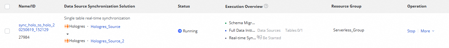
On the Data Integration > Synchronization Task page, find the task and click Start in the Operation column.
-
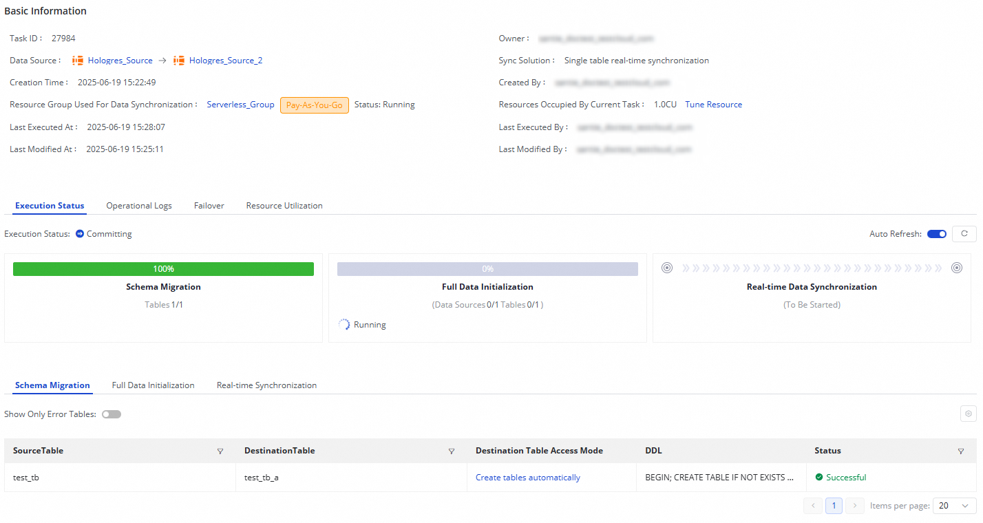
Click the task's Name or ID to open its execution details and monitor progress.
Monitor and manage the task
View task status
After the task starts, go to the Synchronization Task page to see all tasks in the workspace. The task runs through three sequential stages:
| Stage | What it shows |
|---|---|
| Schema Migration | Whether the destination table was auto-created or already existed; the DDL statement for auto-created tables |
| Full Data Initialization | Progress of the initial full data copy (shown only when Synchronization Mode is set to Full initialization) |
| Real-time Data Synchronization | Read and write throughput, dirty data counts, failovers, and operation logs |
From the Operation column, click Start or Stop to control the task. Click More and select Edit to modify it, or View to inspect its details.
Rerun the task
Rerun the task if you need to apply configuration changes or re-sync modified tables.
-
Rerun without changes — click Rerun in the Operation column. The task re-syncs only tables that were modified; tables already in sync are not re-synced.
-
Rerun after configuration changes — modify the task settings, click Complete, then click Apply Updates in the Operation column. The task reruns with the new configuration.