Logic nodes help you set the interaction logic between assets and assets to implement the interaction between assets in the big screen. This topic describes how to configure logical nodes in Blueprint Editor.
Use logical nodes
- Log on to the DataV console.
On the Projects tab, select an existing project and click Edit.
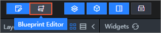
In Canvas Editor, click the Blueprint Editor icon in the top toolbar.
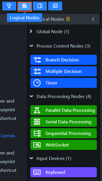
In Blueprint Editor, click the Logical Nodes icon in the top toolbar.
 Note
NoteSkip this step if the Logical Nodes panel is already displayed.
Before you configure a logical node, make sure that you have added widgets to Blueprint Editor. For more information about how to add a blueprint editor, see What is Blueprint Editor?.
In the Logical Nodes panel, drag the required logical nodes to the canvas.
Logical nodes include global nodes, flow control, data processing, and input devices. For more information about how to use each node and the parameters, see Global nodes, Process control, Data processing, and Input devices.
Configure logical nodes
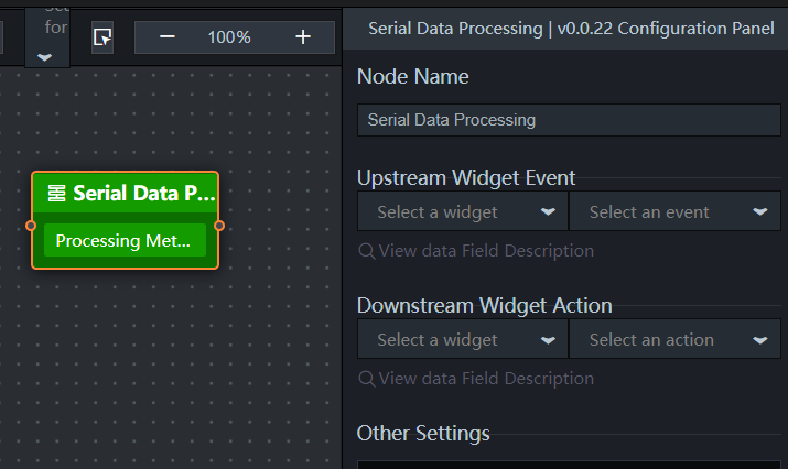
Click a logical node on the canvas or drag it to the canvas. In the right-side configuration pane, configure the node interaction logic. You do not need to configure the global node. The following figure shows the common parameters of logical nodes except global nodes.
Parameter | Description |
Endpoint Name | The name of a custom logical node. Each logical node has its own icon. After a logical node is renamed, you can identify the node type and functions based on its icon. |
Upstream Component Event Description | You can select an upstream widget and its event, and view its parameter description. |
Downstream Component Actions | Select a downstream component and an action, and view the parameter description. |
Solutions | The processing method that you add or configure for the logical interaction functions of each node. You can perform the following operations on the vulnerability:
Important Processing Method does not need to be configured for input devices or WebSocket nodes. |
 ) icon to modify the name of the processing method.
  ) icon to save the processing method to the code snippet management console.