This topic describes how to use route policies to connect your branches to an Internet Data Center (IDC).
Prerequisites
This topic applies only to Basic Edition transit routers.
-
You have created a Cloud Connect Network (CCN) and added the Smart Access Gateway (SAG) instance for your branch to the CCN. For more information, see SAG APP Quick Start or Connect a single device to the cloud.
-
You have created a Cloud Enterprise Network (CEN) instance and attached the network instances that you want to interconnect. For more information, see Create a CEN instance, Create a CCN connection, and Use a Basic Transit Router to create a VBR connection.
-
You have purchased a Bandwidth Plan and configured bandwidth for cross-region connections. For more information, see Use a Bandwidth Plan and Create a cross-region connection.
Background information
By default, the system adds a route policy with a priority of 5000 and the Deny action to the Transit Router (TR) of a CEN instance. This route policy prevents communication between VBRs or CCNs and other VBRs or CCNs that are attached to the CEN instance. In some scenarios, you may need to permit communication between these network instances.
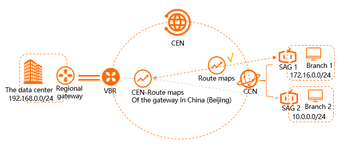
In the scenario shown in the preceding figure, an IDC in the China (Beijing) region connects to Alibaba Cloud through a Virtual Border Router (VBR). Branch 1 is in the China (Shanghai) region and Branch 2 is in the China (Hangzhou) region. SAG 1 and SAG 2 are attached to a CCN instance. The VBR and CCN instances are attached to a CEN instance. By default, the IDC cannot communicate with Branch 1 or Branch 2. To enable communication between the IDC and Branch 1, you can configure a route policy.
Step 1: Allow IDC access to Branch 1
Perform the following steps to configure a route policy to permit the IDC to access Branch 1.
-
Log on to the Cloud Enterprise Network console.
-
On the CEN Instance page, find the target CEN instance and click the instance ID.
-
On the details page of the CEN instance, click the ID of the TR in the region where you want to configure the route policy.
-
On the details page of the TR, click the Route Table tab, and then click Routing Policy.
-
On the Routing Policy page, click Add Route Map. Configure the route policy with the following parameters and click OK.
-
Policy Priority: The priority of the route policy. A smaller value indicates a higher priority. In this example, enter 20.
-
Region: Select the region where the route policy applies. In this example, select China (Beijing).
-
Policy Direction: Select the direction in which the route policy applies. In this example, select Outbound Gateway.
-
Match Condition: Specify the match criteria. In this example, add the following match criteria:
-
Source Instance IDs: The instance ID of SAG 1.
-
Destination Instance IDs: The instance ID of the VBR.
-
Route Prefix: Select Exact match and enter the route prefix
172.16.0.0/24.
-
-
Strategic Behavior: Select the action to apply to matched routes. In this example, select Allow.
After you add the route policy, you can view the route that allows the IDC to access Branch 1 on the Network Instance Route Table tab. On the Network Instance Route Information tab of the transit router instance, you can find a route entry for the destination CIDR block
172.16.0.0/24. The route type is Cloud Enterprise Network, the next hop is CCN in Chinese mainland, and the status is Available. -
Step 2: Allow CCN access to the IDC
Perform the following steps to configure a route policy to permit the CCN to access the IDC.
-
Log on to the Cloud Enterprise Network console.
-
On the CEN Instance page, find the target CEN instance and click the instance ID.
-
On the details page of the CEN instance, click the ID of the TR in the region where you want to configure the route policy.
-
On the details page of the TR, click the Route Table tab, and then click Routing Policy.
-
On the Routing Policy page, click Add Route Map. Configure the route policy with the following parameters and click OK.
-
Policy Priority: The priority of the route policy. A smaller value indicates a higher priority. In this example, enter 20.
-
Region: Select the region where the route policy applies. In this example, select Mainland China CCN.
-
Policy Direction: Select the direction in which the route policy applies. In this example, select Outbound Gateway.
-
Match Condition: Specify the match criteria. In this example, add the following match criteria:
-
Source Instance IDs: The instance ID of the VBR.
-
Destination Instance IDs: The instance ID of the CCN.
-
Route Prefix: Select Exact match and enter the route prefix
192.168.0.0/24.
-
-
Strategic Behavior: Select the action to apply to matched routes. In this example, select Allow.
After you add the route policy, you can view the route that permits CCN to access the IDC on the Network Instance Route Table tab. After the configuration is complete, you can confirm in the route table of the CEN instance that the route entry for the destination CIDR block
192.168.0.0/24has taken effect. The route type is Cloud Enterprise Network and the next hop is China (Beijing). -
Step 3: Test network connectivity
Perform the following steps to test the network connectivity between the IDC and Branch 1.
-
Open the command-line interface (CLI) on a client in the IDC.
-
Run the ping command on the IP address of a client in Branch 1 to verify network connectivity.
If you receive replies as shown in the following output, the IDC can communicate with Branch 1.
C:\Users\Administrator>ping 172.16.0.1 Pinging 172.16.0.1 with 32 bytes of data: Reply from 172.16.0.1: bytes=32 time<1ms TTL=128 Reply from 172.16.0.1: bytes=32 time<1ms TTL=128 Reply from 172.16.0.1: bytes=32 time<1ms TTL=128 Reply from 172.16.0.1: bytes=32 time<1ms TTL=128 Ping statistics for 172.16.0.1: Packets: Sent = 4, Received = 4, Lost = 0 (0% loss), Approximate round trip times in milli-seconds: Minimum = 0ms, Maximum = 0ms, Average = 0ms -
Open the CLI on a client in Branch 1.
-
Run the ping command on the IP address of a client in the IDC to verify network connectivity.
If you receive replies as shown in the following output, Branch 1 can communicate with the IDC.
C:\Users\Administrator>ping 192.168.0.1

Pinging 192.168.0.1 with 32 bytes of data:
Reply from 192.168.0.1: bytes=32 time<1ms TTL=128
Reply from 192.168.0.1: bytes=32 time<1ms TTL=128
Reply from 192.168.0.1: bytes=32 time<1ms TTL=128
Reply from 192.168.0.1: bytes=32 time<1ms TTL=128

Ping statistics for 192.168.0.1:
    Packets: Sent = 4, Received = 4, Lost = 0 (0% loss),
Approximate round trip times in milli-seconds:
    Minimum = 0ms, Maximum = 0ms, Average = 0ms
Perform the following steps to test the network connectivity between the IDC and Branch 2.
-
Open the CLI on a client in the IDC.
-
Run the ping command on the IP address of a client in Branch 2 to verify network connectivity.
If the request times out as shown in the following output, the IDC cannot access Branch 2.
C:\Users\Administrator>ping 10.0.0.1

Pinging 10.0.0.1 with 32 bytes of data:
Request timed out.
Request timed out.
Request timed out.
Request timed out.

Ping statistics for 10.0.0.1:
    Packets: Sent = 4, Received = 0, Lost = 4 (100% loss),