Prepare data for electricity analysis by synchronizing raw CSV files from ApsaraDB RDS for MySQL into MaxCompute. This tutorial walks you through the full data preparation pipeline: registering a MySQL data source in DataWorks, creating a workflow with three offline synchronization nodes, defining the target MaxCompute tables, and verifying that data is written successfully.
By the end of this tutorial, you will have:
Registered an ApsaraDB RDS for MySQL data source in DataWorks Management Center
Created a workflow with one start node and three offline synchronization nodes
Created three MaxCompute tables:
trend_data,indicators_data, andsteal_flag_dataVerified that data is synchronized to MaxCompute
Prerequisites
Before you begin, ensure that you have:
Completed the required environment setup. See Prepare the environment.
Added a MaxCompute data source. See Add a MaxCompute data source.
Prepare a data source
In the ApsaraDB RDS console, create an ApsaraDB RDS for MySQL instance and note the instance ID. See Create an ApsaraDB RDS for MySQL instance and configure databases.
Configure an IP address whitelist for the instance.
If you use a serverless resource group to run synchronization tasks, the whitelist configuration depends on how the resource group accesses the data source: - VPC access: Add the CIDR block of the vSwitch associated with the resource group to the IP address whitelist. - Internet access: Add the elastic IP address (EIP) of the VPC associated with the serverless resource group to the IP address whitelist. For older resource groups, add the resource group's EIP instead. For details, see Network connectivity solutions.
Download the raw data files for this tutorial:
Upload the raw data to the ApsaraDB RDS for MySQL instance. See Import data from an Excel file to ApsaraDB RDS for MySQL.
Add a data source
Add the ApsaraDB RDS for MySQL instance as a DataWorks data source so that synchronization tasks can access it.
Log on to the DataWorks console. In the top navigation bar, select the target region. In the left-side navigation pane, choose More > Management Center. Select your workspace from the drop-down list and click Go to Management Center.
In the left-side navigation pane, choose Data Sources > Data Sources.
Click Add Data Source in the upper-left corner. In the Add Data Source dialog box, click MySQL.
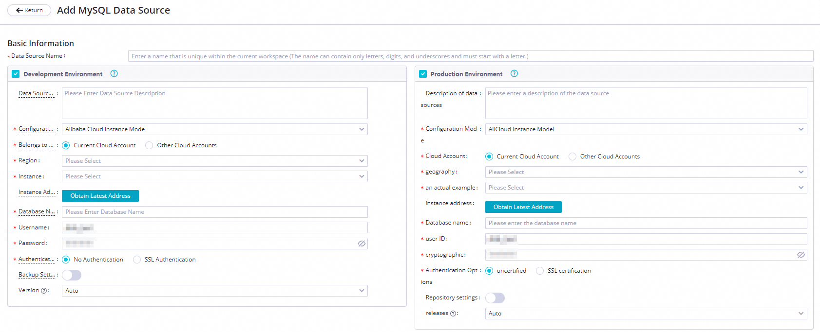
On the Add MySQL Data Source page, set Configuration Mode to Alibaba Cloud Instance Mode and configure the remaining parameters.
Parameter Description Applicable environment The environment where the data source is used. Valid values: Development Environment and Production Environment. Configuration Mode Select Alibaba Cloud Instance Mode. Belongs to Cloud Account Select Current Cloud Account. Region The region where the data source resides. Instance Select the ApsaraDB RDS for MySQL instance you created. After selecting, click Obtain Latest Address to view the instance details. If no instance appears, create one in the ApsaraDB RDS console. Database Name, Username, and Password The default database name and credentials used to connect. Do not use at signs (@) in the password. If you configure a batch synchronization task with multiple databases, add a separate data source for each database. Authentication Options Select No Authentication. Backup Settings If the instance is a primary instance with one or more secondary read-only instances, enable Backup Settings and select the secondary instance ID. This reduces read pressure on the primary instance. If the primary instance has multiple secondary read-only instances, only one of them is read. NoteEnabling Backup Settings requires an exclusive resource group. The task cannot use a serverless resource group.
Test network connectivity. In the Connection Configuration section, click Data Integration and Data Scheduling separately. For each resource group you plan to use, click Test Network Connectivity in the Connection Status column.
If the status shows Connected, the resource group can reach the data source.
If the status does not show Connected, check your IP address whitelist and VPC configuration. For troubleshooting guidance, see Network connectivity solutions.
A synchronization task can use only one resource group of each type. Test connectivity for all resource group types your task will use.
Click Complete Creation.
Create a workflow
In the upper-left corner of the Management Center page, click the
 icon and choose All Products > Data Development And Task Operation > DataStudio.
In DataStudio, right-click Business Flow and select Create Workflow.
In the Create Workflow dialog box, enter a Workflow Name and Description, then click Create.
The workflow name can contain letters, digits, underscores (_), and periods (.), up to 128 characters.
On the workflow canvas, drag one zero load node and three offline synchronization nodes onto the canvas. Name the zero load node
start. The three offline synchronization nodes will synchronize electricity usage trend data, electricity-stealing flag data, and metric data.Connect the nodes so that
startis the ancestor node of all three offline synchronization nodes.Click Submit.
Configure the start node
Double-click the
startnode. In the right-side panel, click the Properties tab.Set the workspace root node as the ancestor node of the
startnode. The root node is named in the format{WorkspaceName}_root.Every node in DataWorks must have an ancestor node and a descendant node. Linking the start node to the workspace root node satisfies this requirement.
Click the
 icon to save.
Create tables
Create three MaxCompute tables to store the synchronized data.
Right-click the workflow and choose Create Table > MaxCompute > Table.
In the Create Table dialog box, configure Engine Instance, Path, and Name, then click Create. Create three tables:
Table names can be up to 64 characters, must start with a letter, and cannot contain special characters.
Table name Stores trend_dataElectricity usage trend data indicators_dataMetric data steal_flag_dataElectricity-stealing flag data On the configuration tab for each table, click DDL and enter the corresponding CREATE TABLE statement:
-- Create a table to store electricity usage trend data.
CREATE TABLE trend_data (
    uid BIGINT,
    trend BIGINT
)
PARTITIONED BY (dt string);
-- Create a table to store metric data. CREATE TABLE indicators_data ( uid BIGINT, xiansun BIGINT, warnindicator BIGINT ) COMMENT '*' PARTITIONED BY (ds string) LIFECYCLE 36000;-- Create a table to store electricity-stealing flag data. CREATE TABLE steal_flag_data ( uid BIGINT, flag BIGINT ) COMMENT '*' PARTITIONED BY (ds string) LIFECYCLE 36000;Click Generate Table Schema, then click OK.
In the General section, enter a display name for each table.
Click Commit to Development Environment, then click Commit to Production Environment.
Configure the offline synchronization nodes
Configure each offline synchronization node to move data from MySQL to MaxCompute. The steps below use the trend data node as an example; repeat the same configuration for the other two nodes.
Double-click the offline synchronization node to open its configuration tab.
Configure the source:
Parameter Value Connection Select MySQL > workshop Table Select trendingFilter (Optional) A SQL WHERE condition to filter rows. The LIMIT keyword is not supported. Shard Key (Optional) When set, data is split across parallel threads, which improves synchronization throughput. Configure the destination:
Parameter Value Connection Select ODPS, then select your MaxCompute data source Table Select trend_dataPartition Key Column Default: dt=${bdp.system.bizdate}Writing Rule Select Write with Original Data Deleted (Insert Overwrite) Convert Empty Strings to Null Select No Configure field mappings between the source and destination.
Configure the Channel settings:
Parameter Description Expected Maximum Concurrency The maximum number of parallel threads for reading from the source or writing to the destination. Bandwidth Throttling Enable throttling and set a maximum transmission rate to limit read pressure on the source. Set this based on your source database capacity. Dirty Data Records Allowed The maximum number of dirty data records allowed. 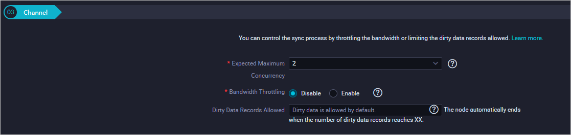
Click the
icon to save.
Commit the workflow
On the workflow canvas, click the
 icon.
icon.In the Commit dialog box, select the nodes to commit, enter comments in Change description, and select Ignore I/O Inconsistency Alerts.
Click Commit. The Committed successfully message confirms the workflow is committed.
Verify data synchronization
Run an ad-hoc query to confirm that data has been written to each MaxCompute table.
In the left-side navigation pane, click Ad-Hoc Query.
Right-click Ad-Hoc Query and choose Create Node > ODPS SQL.
Run the following SQL statements. Replace
<data_timestamp>with the business date of the node run—one day before the scheduling date. For example, if the node runs on August 9, 2019, use20190808.-- Check whether data is written to MaxCompute. SELECT COUNT(*) FROM trend_data WHERE dt=<data_timestamp>; SELECT COUNT(*) FROM indicators_data WHERE ds==<data_timestamp>; SELECT COUNT(*) FROM steal_flag_data WHERE ds=<data_timestamp>;Each query should return a non-zero row count, confirming that data was synchronized successfully.
What's next
With data synchronized to MaxCompute, you are ready to compute and analyze the collected data. Proceed to the next tutorial to set up data processing tasks.