By Wang Xining, Senior Alibaba Cloud Technical Expert
A service mesh is a dedicated infrastructure layer that aims to improve inter-service communication. It is currently the hottest topic in the cloud native field. As containers become more widely used, we will need better network performance to deal with the frequent changes in service topologies. A service mesh helps us manage network traffic through service discovery, routing, load balancing, heartbeat detection, and observability support. A service mesh attempts to provide standard solutions to irregular and complex container problems.
A service mesh can also be used for chaos engineering, a discipline that conducts experiments on distributed systems in order to build reliable systems able to cope with extreme conditions. A service mesh can inject latency and errors into environments, without having to install a daemon process on each host.
Containers are the foundation of cloud native applications. Containerization makes application development and deployment more agile and migration more flexible. All these implementations are based on standards. Container orchestration provides ways to orchestrate resources more effectively and to schedule and use these resources more efficiently. In the cloud native era, we can combine Kubernetes with the Istio service mesh to support multi-cloud and hybrid cloud environments. We can also implement effective microservice governance and provide differentiated support for specific application loads. For example, we can provide Knative-dedicated load routing management to improve Kubeflow's traffic governance.
Despite the rapid growth of service mesh applications in cloud native systems, service mesh still has much room for improvement. Serverless computing requires a service mesh naming and linkage model. This makes the service mesh more important for the cloud native ecosystem. A service mesh provides a necessary and fundamental way to upgrade service identification and access policies in a cloud native environment. Like TCP/IP, service mesh technology will be better adapted to the underlying infrastructure.
Hybrid clouds can take many forms. Hybrid clouds connect public clouds and internally deployed private clouds. Multi-cloud environments include multiple public cloud platforms.
Hybrid cloud and multi-cloud environments can benefit your organization in many ways. For example, you can subscribe to multiple cloud service providers to avoid being locked into a vendor and have the ability to select the optimal cloud service to achieve your goals. The cloud provides benefits such as flexibility, scalability, and low costs. An on-premises environment provides security, low latency, and reusable hardware. With a hybrid cloud, you can run your businesses both on the cloud and in an on-premises environment to enjoy all these benefits. When you migrate your businesses to the cloud for the first time, you can deploy them on a hybrid cloud so that you can control the migration progress as needed.
Based on our practical experience with public clouds and customer feedback, we believe a hybrid service network provides important means by which to simplify the management, security measures, and reliability assurance measures for applications deployed both on the cloud and in an on-premises environment. This approach is suitable regardless of whether your applications run in containers or on virtual machines (VMs).
Istio provides service abstraction for your workloads, such as pods, jobs, and VM-based applications. Service abstraction can help you effectively cope with multiple environments when working with a hybrid topology.
When you apply Istio to a Kubernetes cluster, you gain all the advantages of microservice management, including visibility, fine-grained traffic policies, unified telemetry, and security. When you apply Istio to multiple environments, you actually provide a new super capability to your applications. This is because Istio is both a service abstraction of Kubernetes and a method to standardize the network in the entire environment. Istio supports centralized API management and separates JSON Web Token (JWT) verification from code. Istio can be viewed as a fast, secure, and zero-trust network that spans different cloud service providers.
How does Istio do this? Hybrid Istio is a group of Istio sidecar proxies. Each Envoy proxy is located beside all services, which may run on every VM and in every container in different environments. The sidecar proxies know how to interact with each other across boundaries. These Envoy sidecar proxies may be managed by a central Istio control plane or multiple control planes running in each environment.
In essence, a service mesh combines a group of separate microservices into a single controllable composite application. Istio is a service mesh designed to monitor and manage cooperative microservice networks under a single management domain. For applications of a specific size, all microservices can run on a single orchestration platform, such as a Kubernetes cluster. However, due to the increasing scale or the need for redundancy, most applications have to distribute some services to other environments.
The community is increasingly focused on how to run workloads in multiple clusters for better scaling. This can effectively isolate failures and improve application agility. Istio 1.0 and later versions support multi-cluster functionality and other new features.
The Istio service mesh supports many possible topologies, which are used to distribute application services outside a single cluster. Two models or use cases are commonly used: single service mesh and service mesh federation. A single service mesh combines multiple clusters into a unit that is managed by the Istio control plane. This unit can be implemented as a physical control plane or a group of control planes that can synchronize with each other through configuration replication. In service mesh federation, multiple clusters run as separate management domains and are connected to each other selectively. Each cluster exposes only a subset of services to the other clusters. Service mesh federation includes multiple control planes.
These different topologies are divided into the following types:
Istio 1.0 only supports single-mesh design for multi-cluster management. This design allows multiple clusters to connect to a service mesh while running in the same shared network. In other words, the IP addresses of all pods and services in all clusters support direct routing and are free of conflicts. The IP addresses assigned to one cluster are not reused in another cluster.
In this topology, a single Istio control plane runs in one of the clusters. The control plane Pilot manages services in the local and remote clusters and configures Envoy proxies for all clusters. This approach works best in an environment where all participating clusters have VPN connections. Therefore, each pod in the service mesh can be accessed from anywhere else by using the same IP address.
In this configuration, the Istio control plane is deployed in one of the clusters. All the other clusters run simpler remote Istio configurations, which are used to connect them to the single Istio control plane. This control plane manages all Envoy proxies as a single service mesh. The IP addresses cannot overlap between clusters. Domain name server (DNS) resolution is not automatic for services in remote clusters. You need to replicate services in each involved cluster. This allows the Kubernetes cluster services and applications in each cluster to expose their internal Kubernetes networks to the other clusters. Once one or more remote Kubernetes clusters are connected to the Istio control plane, Envoy can communicate with the single control plane and form a mesh network across multiple clusters.
A variety of constraints restrict the interactions among service meshes, clusters, and networks. For example, networks are directly related to clusters in some environments. Designed with a single Istio service mesh, the VPN connection topology with a single control plane must satisfy the following conditions:
The topology must also use the RFC 1918 network, VPN, or more advanced network technologies that meet the following requirements:
To support DNS name resolution across clusters, you must define namespaces, services, and service accounts in all clusters that require cross-cluster service calls. For example, assume that Service 1 in the namespace ns1 of Cluster 1 needs to call Service 2 in the namespace ns2 of Cluster 2. To support DNS resolution of the service names in Cluster 1, you must create a namespace called ns2 in Cluster 1 and create Service 2 in this namespace.
In the following example, the networks of the two Kubernetes clusters are assumed to meet the preceding requirements, and the pods in each cluster are mutually routable. This means the network is available and the ports are accessible. If you use a public cloud service similar to Alibaba Cloud, ensure that these ports are accessible under security group rules. Otherwise, calls between services will be affected.
The following table lists the pod CIDR blocks and service CIDR blocks of the two Kubernetes clusters.

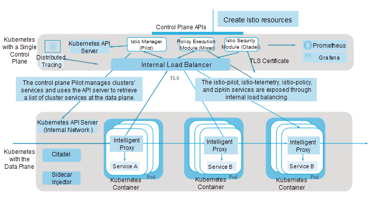
As shown in the preceding figure, in the multi-cluster topology, the Istio control plane is installed in only one Kubernetes cluster. This cluster is called a local cluster, and all the other clusters are called remote clusters.
These remote clusters only need to install Istio's Citadel and sidecar injector as access controllers, which occupy a small space in Istio. Citadel is used to manage the security of these remote clusters. The sidecar injector is used for automatic injection at the control plane and provides the sidecar proxy function for workloads at the data plane.
In this architecture, Pilot can access all Kubernetes API servers in all clusters, giving it a global view of network access. Citadel and the sidecar injector only run in the local cluster. Each cluster has unique pods and service CIDR blocks. Clusters share a flat network to ensure direct routing to any workloads and the Istio control plane. For example, the Envoy proxies in the remote clusters must retrieve configurations from Pilot, and check and report the configurations to Mixer.
To enable cross-cluster two-way TLS communication for multiple clusters, deploy and configure each cluster as follows. First, generate an intermediate CA certificate for each cluster's Citadel based on the shared root CA certificate. Enable cross-cluster two-way TLS communication by using the shared root CA certificate. For simplicity, we will apply the sample root CA certificate provided during Istio installation in the samples/certs directory to two clusters. In actual deployment, you may apply a different CA certificate to each cluster. All CA certificates are signed by a public root CA.
Create a key for each Kubernetes cluster, Cluster 1 and Cluster 2 in this example. Run the following commands to create a Kubernetes key for the generated CA certificate:
kubectl create namespace istio-system
kubectl create secret generic cacerts -n istio-system \
  --from-file=samples/certs/ca-cert.pem \
  --from-file=samples/certs/ca-key.pem \
  --from-file=samples/certs/root-cert.pem \
  --from-file=samples/certs/cert-chain.pem
You can skip the preceding steps if your environment is only for development and testing or does not need to enable two-way TLS communication.
You can install an Istio control plane in the local cluster in a way similar to installing Istio in a single cluster. Pay special attention to how to configure the Envoy proxy to manage the parameters that are used to directly access the external services in a specific IP address range. If you use Helm to install Istio, ensure that the global.proxy.includeIPRanges variable in Helm is an asterisk (*) or includes the pod CIDR blocks and service CIDR blocks of the local clusters and all the remote clusters.
You can check the global.proxy.includeIPRanges setting based on traffic.sidecar.istio.io/includeOutboundIPRanges of the istio-sidecar-injector configuration item in the istio-system namespace, as shown in the following figure.
kubectl get configmap istio-sidecar-injector -n istio-system -o yaml| grep includeOutboundIPRangesTo deploy the Istio control plane components in Cluster 1, perform the following steps:
If two-way TLS communication is enabled, set the following parameters:
helm template --namespace=istio-system \
  --values
install/kubernetes/helm/istio/values.yaml \
  --set global.mtls.enabled=true \
  --set security.selfSigned=false \
  --set global.controlPlaneSecurityEnabled=true
\
  install/kubernetes/helm/istio > istio-auth.yaml
kubectl
apply -f istio-auth.yaml
If two-way TLS communication is not enabled, modify the parameter settings as follows:
helm template --namespace=istio-system \
  --values
install/kubernetes/helm/istio/values.yaml \
  --set global.mtls.enabled=false \
  --set security.selfSigned=true \
  --set global.controlPlaneSecurityEnabled=false
\
  install/kubernetes/helm/istio >
istio-noauth.yaml
kubectl
apply -f istio-noauth.yaml
Change Istio's istio-pilot, istio-telemetry, istio-policy, and zipkin service types to internal load balancing. Expose these services to the remote clusters through the internal network. You can do this through annotation modification, no matter what cloud service provider you are using. If you are using Alibaba Cloud Container Service, you can configure internal load balancing simply by adding the following annotation to the services' YAML definitions:
service.beta.kubernetes.io/alicloud-loadbalancer-address-type: intranet.
Configure each service based on the port definitions shown in the following figure.
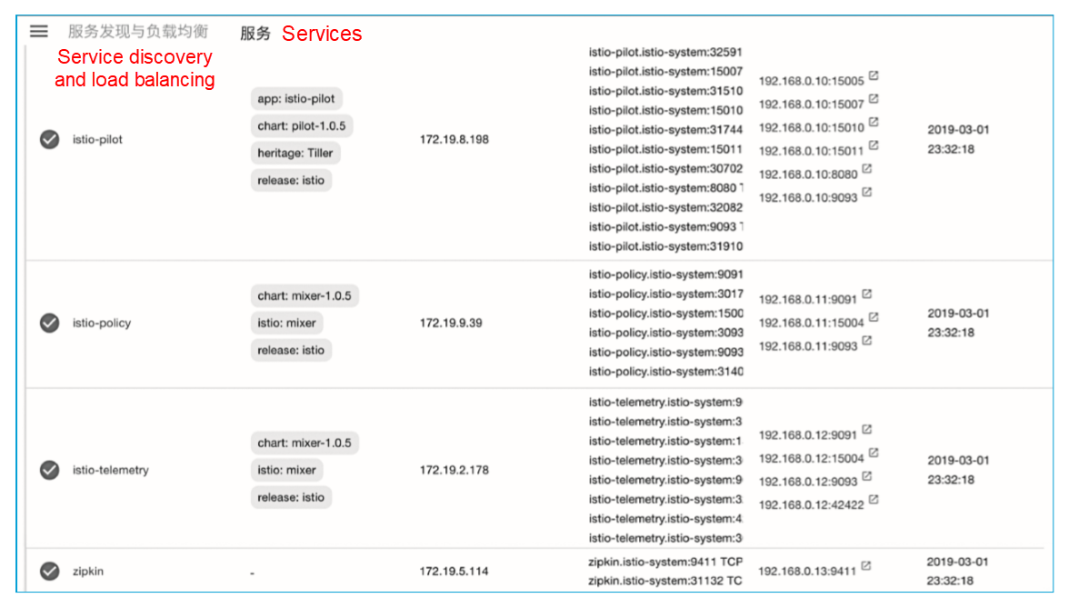
Table 1 lists the service ports of istio-pilot.
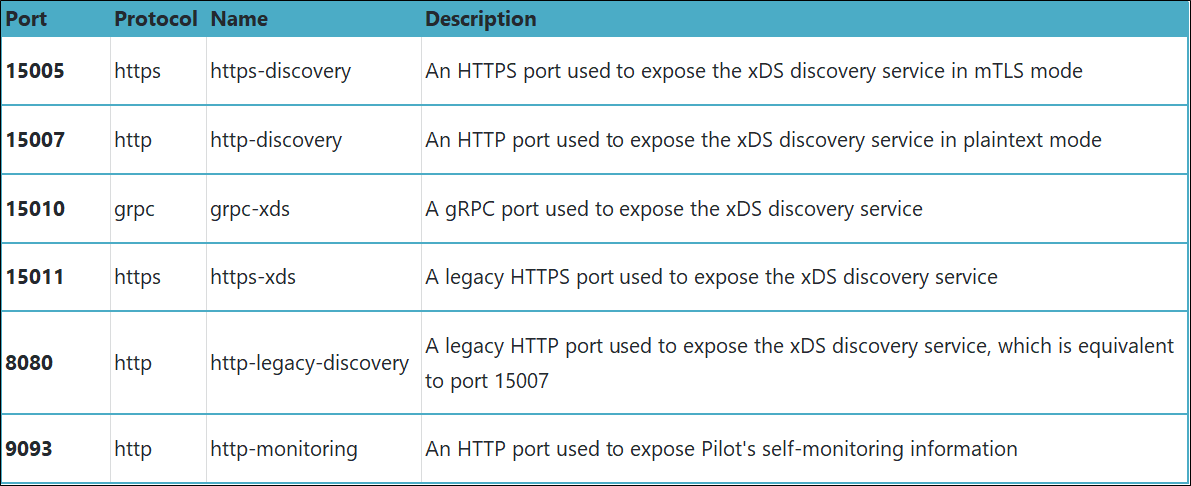
Table 2 lists the service ports of istio-telemetry.
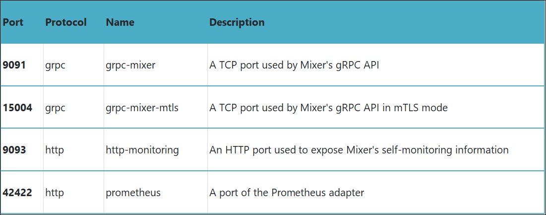
Table 3 lists the service ports of istio-policy.

Table 4 lists the service ports of zipkin.

After installing the control plane in the local cluster, you must deploy the istio-remote component to each remote Kubernetes cluster. Wait until the Istio control plane initialization is complete and then perform the steps in this section. You can perform these operations in the cluster where the Istio control plane is installed to capture the Istio control plane's service endpoints, such as the istio-pilot, istio-telemetry, istio-policy, and zipkin service endpoints.
To deploy the istio-remote component in remote Cluster 2, follow these steps:
1) Run the following commands in the local cluster to set environment variables:
export
PILOT_IP=$(kubectl -n istio-system get service istio-pilot -o
jsonpath='{.status.loadBalancer.ingress[0].ip}')
export
POLICY_IP=$(kubectl -n istio-system get service istio-policy -o
jsonpath='{.status.loadBalancer.ingress[0].ip}')
export
TELEMETRY_IP=$(kubectl -n istio-system get service istio-telemetry -o
jsonpath='{.status.loadBalancer.ingress[0].ip}')
export
ZIPKIN_IP=$(kubectl -n istio-system get service zipkin -o
jsonpath='{.status.loadBalancer.ingress[0].ip}')
echo
$PILOT_IP $POLICY_IP $TELEMETRY_IP $ZIPKIN_IP
2) To enable cross-cluster two-way TLS communication for multiple clusters, configure each cluster accordingly.
You can skip Step 2 if your environment is only for development and testing or does not need to enable two-way TLS communication. Run the following commands in remote Kubernetes Cluster 2 to create a Kubernetes key for the cluster's CA certificate:
kubectl
create namespace istio-system
kubectl
create secret generic cacerts -n istio-system \
    --from-file=samples/certs/ca-cert.pem \
    --from-file=samples/certs/ca-key.pem \
    --from-file=samples/certs/root-cert.pem \
--from-file=samples/certs/cert-chain.pem
3) Run the following command in remote Kubernetes Cluster 2 to create the istio-remote deployment YAML file by using Helm.
If two-way TLS communication is enabled, set the following parameters:
helm
template install/kubernetes/helm/istio \
  --name istio-remote \
  --namespace istio-system \
  --values install/kubernetes/helm/istio/values-istio-remote.yaml
\
  --set global.mtls.enabled=true \
  --set security.selfSigned=false \
  --set global.controlPlaneSecurityEnabled=true
\
  --set
global.remotePilotCreateSvcEndpoint=true \
  --set global.remotePilotAddress=${PILOT_IP} \
  --set global.remotePolicyAddress=${POLICY_IP}
\
  --set
global.remoteTelemetryAddress=${TELEMETRY_IP}
  --set global.remoteZipkinAddress=${ZIPKIN_IP}
> istio-remote-auth.yaml
Run the following command to deploy the istio-remote component to Cluster 2:
kubectl apply -f ./istio-remote-auth.yamlIf two-way TLS communication is not enabled, modify the parameter settings as follows:
helm
template install/kubernetes/helm/istio \
  --name istio-remote \
  --namespace istio-system \
  --values
install/kubernetes/helm/istio/values-istio-remote.yaml \
  --set global.mtls.enabled=false \
  --set security.selfSigned=true \
  --set
global.controlPlaneSecurityEnabled=false \
  --set
global.remotePilotCreateSvcEndpoint=true \
  --set global.remotePilotAddress=${PILOT_IP} \
  --set global.remotePolicyAddress=${POLICY_IP}
\
  --set global.remoteTelemetryAddress=${TELEMETRY_IP}
  --set global.remoteZipkinAddress=${ZIPKIN_IP}
> istio-remote-noauth.yaml
Run the following command to deploy the istio-remote component to Cluster 2:
kubectl
apply -f ./istio-remote-noauth.yaml
Ensure that the preceding steps were successfully performed in all Kubernetes clusters.
4) Create a kubeconfig file in Cluster 2.
After the istio-remote Helm chart is installed, a Kubernetes service account named istio-multi is created in each remote cluster. This service account is used to minimize access requests under role-based access control (RBAC). The corresponding cluster role is defined as follows:
kind:
ClusterRole
apiVersion:
rbac.authorization.k8s.io/v1
metadata:
  name: istio-reader
rules:
  - apiGroups: ['']
    resources: ['nodes', 'pods', 'services',
'endpoints']
    verbs: ['get', 'watch', 'list']
The following process creates a kubeconfig file for each remote cluster by using the istio-multi service account credentials. Run the following command to create a kubeconfig file for Cluster 2 by using the istio-multi service account and save the file with the name n2-k8s-config.
CLUSTER_NAME="cluster2"
SERVER=$(kubectl
config view --minify=true -o "jsonpath={.clusters[].cluster.server}")
SECRET_NAME=$(kubectl
get sa istio-multi -n istio-system -o jsonpath='{.secrets[].name}')
CA_DATA=$(kubectl
get secret ${SECRET_NAME} -n istio-system -o
"jsonpath={.data['ca\.crt']}")
TOKEN=$(kubectl
get secret ${SECRET_NAME} -n istio-system -o
"jsonpath={.data['token']}" | base64 --decode)
cat
<<EOF > n2-k8s-config
apiVersion:
v1
kind:
Config
clusters:
  - cluster:
      certificate-authority-data: ${CA_DATA}
      server: ${SERVER}
    name: ${CLUSTER_NAME}
contexts:
  - context:
      cluster: ${CLUSTER_NAME}
      user: ${CLUSTER_NAME}
    name: ${CLUSTER_NAME}
current-context:
${CLUSTER_NAME}
users:
  - name: ${CLUSTER_NAME}
    user:
      token: ${TOKEN}
EOF
5) Add Cluster 2 to the cluster where Istio Pilot is located.
Run the following commands in Cluster 1 to add Cluster 2's kubeconfig file to "secret" of Cluster 1. Then, Cluster 1's Istio Pilot listens to Cluster 2's services and instances just as it listens to its own services and instances.
kubectl
create secret generic n2-k8s-secret --from-file n2-k8s-config -n istio-system
kubectl
label secret n2-k8s-secret istio/multiCluster=true -n istio-systemTo illustrate cross-cluster access, this section demonstrates the following deployment process: (1) Deploy the Sleep application service and the Helloworld service v1 to Kubernetes Cluster 1; (2) Deploy the Helloworld service v2 to Cluster 2; and (3) Verify that the Sleep application can call the Helloworld service of the local or remote cluster.
1) Run the following commands to deploy the Sleep service and the Helloworld service v1 to Cluster 1:
kubectl
create namespace app1
kubectl
label namespace app1 istio-injection=enabled
kubectl
apply -n app1 -f multicluster/sleep/sleep.yaml
kubectl
apply -n app1 -f multicluster/helloworld/service.yaml
kubectl
apply -n app1 -f multicluster/helloworld/helloworld.yaml -l version=v1
export
SLEEP_POD=$(kubectl get -n app1 pod -l app=sleep -o
jsonpath={.items..metadata.name})
2) Run the following commands to deploy the Helloworld service v2 to Cluster 2:
kubectl
create namespace app1
kubectl
label namespace app1 istio-injection=enabled
kubectl
apply -n app1 -f multicluster/helloworld/service.yaml
kubectl
apply -n app1 -f multicluster/helloworld/helloworld.yaml -l version=v2
3) Run the following command in Cluster 1 to verify that the Sleep service can call the Helloworld service of the local or remote cluster:
kubectl
exec $SLEEP_POD -n app1 -c sleep -- curl helloworld.app1:5000/hello
If the settings are correct, the returned call result includes two versions of the Helloworld service. You can view the istio-proxy container log of the Sleep container group to verify the IP address of the accessed endpoint. The returned result is as follows:

4) Verify that the Istio routing rules are effective.
Create routing rules for the two Helloworld service versions to check whether the Istio configurations work properly.
Run the following command to create the Istio virtual service VirtualService:
kubectl
apply -n app1 -f multicluster/helloworld/virtualservice.yaml
Create an Istio DestinationRule as follows:
If two-way TLS communication is enabled, set the following parameters:
kubectl
apply -n app1 -f multicluster/helloworld/destinationrule.yaml
If two-way TLS communication is not enabled, modify the parameter settings. Add trafficPolicy.tls.mode:ISTIO_MUTUAL to the YAML definition as follows:
apiVersion:
networking.istio.io/v1alpha3
kind:
DestinationRule
metadata:
  name: helloworld
spec:
  host: helloworld
  **trafficPolicy:
  tls:
    mode: ISTIO_MUTUAL**
  subsets:
  - name: v1
  labels:
    version: v1
  - name: v2
  labels:
    version: v2
Run the kubectl apply command to create an Istio DestinationRule for enabling two-way TLS communication:
kubectl
apply -n app1 -f multicluster/helloworld/destinationrule-auth.yaml
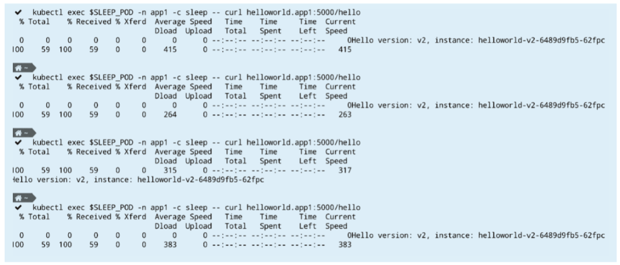
If the Helloworld service is called multiple times, only the response specific to version 2 is returned, as shown in the following figure.
Simplification and Extension of Alibaba Cloud Service Mesh Based on Wasm and ORAS

56 posts | 8 followers
FollowXi Ning Wang(王夕宁) - December 16, 2020
Xi Ning Wang(王夕宁) - December 16, 2020
Alibaba Container Service - May 23, 2025
Alibaba Cloud Native Community - December 18, 2023
Hironobu Ohara - May 18, 2023
5544031433091282 - April 7, 2025

56 posts | 8 followers
Follow Container Service for Kubernetes
Alibaba Cloud Container Service for Kubernetes is a fully managed cloud container management service that supports native Kubernetes and integrates with other Alibaba Cloud products.
Learn More ACK One
Provides a control plane to allow users to manage Kubernetes clusters that run based on different infrastructure resources
Learn More ApsaraDB for MyBase
ApsaraDB Dedicated Cluster provided by Alibaba Cloud is a dedicated service for managing databases on the cloud.
Learn More Microservices Engine (MSE)
MSE provides a fully managed registration and configuration center, and gateway and microservices governance capabilities.
Learn MoreMore Posts by Xi Ning Wang(王夕宁)