Today, map software is an important part of daily travel. A prerequisite for accurate navigation is accurately locating the current position of the driver or vehicle. Therefore, positioning technology is the foundation of navigation functions.
This article systematically introduces the key technologies used in navigation and positioning systems installed in mobile phones and vehicles, as well as the progress of AMAP, also known as AutoNavi, in these key technologies. Besides, it discusses the evolution path of positioning technology beginning from traditional navigation to automated driving.
The core service goal of navigation positioning is to consistently provide reliable location information for navigation services. It seeks to provide the users with details such as which road they are on, whether they have deviated from the route, how far it is to the next intersection, and various such important information.
To accomplish this goal, it's imperative to first receive positioning signal input. The most common positioning signal is from the Global Positioning System (GPS), which provides position information precise to 5 to 10 meters for all scenarios. In addition, most mobile phones are equipped with inertial sensors (gyroscopes and accelerometers) and magnetometers, and some even have barometers to perceive changes in elevation.
Onboard systems have additional significant positioning inputs such as vehicle speed pulse, steering wheel angle, and other information obtained through the Controller Area Network (CAN) bus. Based on these positioning signals, a continuous and reliable position and attitude are calculated by applying attitude fusion, dead reckoning, and other algorithms. Further, a map is used to illustrate the actual location of the driver or vehicle on the road based on map data. This helps to determine whether the vehicle or driver has deviated from the navigation route and to update the relative location in real-time.

Figure 1. Navigation positioning framework
In the preceding positioning framework, the configurations of the input positioning signals are distinct for different terminal types, such as a mobile phone or vehicle. Accordingly, the positioning technology used and the positioning scenarios may also differ.
Mobile phones are used while walking, cycling, or driving, so it's critical to identify the exact user behavior. In walking scenarios, due to the low speed, the GPS direction is not accurate, and the mobile phone attitude is obtained by combining inertial navigation and magnetometer calculation. While driving, the location and attitude of a vehicle are mainly provided by the GPS. In this case, the key problem is to develop reliable map matching algorithms to handle GPS jump, drift, and other complex situations.
If the navigation terminal is a vehicle, only the driving scenario must be considered. At the same time, the system is installed at a fixed position in the vehicle and more positioning information is provided by the CAN bus. Therefore, the dead reckoning and fusion algorithms are designed with this in mind, which allows the system to solve the problems caused by tunnels, elevated roads, parallel roads, and other complex scenarios. This is a key concern of on-board positioning systems.
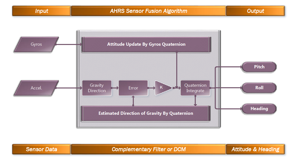
The most common attitude fusion technology is called an attitude and heading reference system (AHRS). The AHRS algorithm for six-axis inertial sensor fusion including a gyroscope and accelerometer is shown in the following figure. The gyroscope measures angular velocity, whereas angular velocity integration is used to obtain the angular change over a certain period of time. The accelerometer measures the acceleration of the object, including gravitational acceleration. When the object is at rest, the relative inclination angle is calculated by obtaining the component of gravitational acceleration along three axes. The AHRS algorithm uses filtering methods, such as complementary filtering and Kalman filtering, to fuse different sensor attitudes.

Figure 2. AHRS fusion algorithm
For a nine-axis sensor, three magnetometer axes are added, and the same algorithm framework as the previous one is used for fusion.
The traditional map matching method aims to find the most likely matching road among the roads near the anchor point according to certain judging criteria, such as the distance and direction of approach. This method is simple to implement. However, a GPS positioning deviation occurs, which is normally about 10 meters but may escalate up to dozens or hundreds of meters in the case of signal interference or obstruction. Moreover, the deviation caused by mapping and map simplification may add another 10 to several dozen meters. Under various deviation conditions, it's difficult to simply rely on geometric feature judgments such as the distance and direction for matching.
While developing a map matching algorithm, in order to determine the matching road reliably and accurately, it is necessary to make full use of various input data from the positioning source and map to perform fusion calculation. In addition, using the features of onboard positioning systems helps to deal with various special scenarios. For multi-source information fusion, the Hidden Markov Model (HMM) is a common and effective method. Therefore, we use the HMM as the core of our matching algorithm, supplemented by scenario-based policy algorithms, to perform map matching.
In an HMM map matching algorithm, the matching road is unknown and used as 'zn', the hidden variable. The GPS positioning information observed at each moment is indicated by the 'xn' observation variable. The goal of map matching is to estimate the matching road from the known positioning information:

To solve the preceding problem, use the Viterbi algorithm for recursive calculation.
The key to establishing a map matching model under the HMM framework is to determine the emission probability model and transition probability model. To determine the emission probability model, we need the position and direction.
1) Based on the positioning location, the closer the road, the higher the probability. At the same time, we must consider that the selection of matching roads is sensitive to horizontal distance errors but less sensitive to vertical distance errors. We use a normal distribution to establish the model.
2) Based, on the positioning direction, the closer the direction of a road, the higher the probability. On the other hand, the probability is related to speed. Thus, the higher the speed, the greater the confidence in the match. We use a Von Mises distribution to build a model with the speed as a hyperparameter.

Figure 3. Position emission probability Figure 4. Direction emission probability
The determination of the transition probability model is based on the constraints of driving behavior owing to road distances and road angles.
The sharper the angles of a road, the lower the probability of driving at high speeds. We use a Von Mises distribution to build a model with the speed as a hyperparameter. The moving distance is calculated according to the vehicle speed and time. The closer this distance is to the moving distance along the road, the greater the probability that this road is a match. We use an index distribution to establish the model.

Figure 5. Speed transition probability Figure 6. Transition probability of moving distance
The preceding algorithm has been implemented in the AMAP app, where it provides accurate positioning and matching results for driving navigation. It can be used in navigation guidance, location broadcast, and other functions. Compared with the original policy-based map matching methods, the HMM algorithm method significantly improves matching accuracy and reliability.
The core problem for vehicle navigation is how to make full use of vehicle sensors and bus information to optimize vehicle navigation in complex scenarios. These complex scenarios include positioning failures in tunnels and underground parking lots and position drift when surrounded by tall buildings.
The key to solving these pain points lies in multi-sensor fusion technology. For example, when GPS locations drift or fail, the dead reckoning technology together with the vehicle speed pulse and inertial navigation provides continuous positioning. However, errors will accumulate, so map data must be used for feedback correction. At the same time, map data and GPS calibrate inertial navigation parameters to improve the accuracy of dead reckoning.
In actual vehicle navigation projects, different positioning solutions are derived based on different sensor configurations, as shown in the following table.
| Positioning solution | Hardware costs | Positioning performance | Signal drift suppression | GNSS loss extrapolation | Quick matching with small-angle bifurcation | Precise positioning of start point | Roundabout high-precision matching | Precise tunnel extrapolation | Continuous positioning in underground parking lots | Upper and lower roadway identification | Main and auxiliary road identification |
|---|---|---|---|---|---|---|---|---|---|---|---|
| GNSS | Low | Basic | ★ | ||||||||
| Frontend fusion | Highest | Good | ★★ | ★★ | ★ | ★ | ★ | ★★ | ★ | ★ | — |
| Vehicle model | Relatively low | Good | ★★☆ | ★★☆ | ★ | ★★ | ★★ | ★★ | ★★ | — | ★ |
| Backend fusion | Relatively high | Excellent | ★★☆ | ★★☆ | ★★☆ | ★★☆ | ★★☆ | ★★☆ | ★★☆ | ★★☆ | ★★☆ |
Among these solutions, the pure Global Navigation Satellite System (GNSS) solution cannot use any sensor fusion methods. Thus, it provides the worst positioning performance. The frontend fusion solution implements the fusion of inertial navigation and vehicle speed at the front end, allowing it to provide continuous positioning in some GPS failure cases. However, since it is subject to the accumulated error, it provides only a limited improvement. Both the vehicle model and backend fusion solutions achieve the complete fusion of sensor, GPS, and map data, and thus, provide superior positioning performance. In addition, the vehicle model solution uses the vehicle's CAN bus sensor data, whereas the backend fusion solution uses the inertial navigation sensor installed on the vehicle. After carefully choosing sensors and adapting the installation and usage, this solution provides optimal performance.
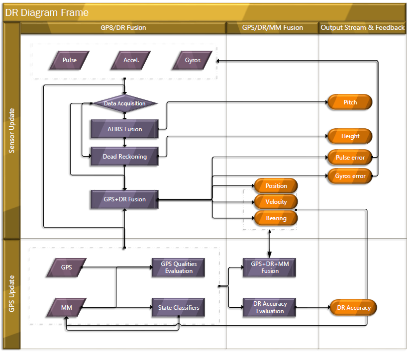
The sensor fusion algorithm framework for the backend fusion solution is shown in the following figure.

Figure 7. A framework of the sensor fusion algorithm
The fusion algorithm is designed for two purposes. First, it integrates navigation information from different technologies into unique navigation information, making it more reliable. Second, it estimates device errors, such as the gyroscope zero offset and velocimeter scale error.
The fusion algorithm is implemented based on Kalman filtering and relies on proper model establishment and model parameter configuration. The Kalman filter model consists of a state transition equation and an observation equation. The state transition equation represents the transitional relationships between adjacent navigation states and is implemented by constructing a differential equation for the navigation error. The model parameters are state transition noise and observation noise. The value of the observation noise is related to the GPS quality evaluation module. After Kalman filtering, it's possible to obtain the optimal estimate of the navigation error.
Sensor fusion technology that implements complete information fusion may either match or even surpass the positioning performance of expensive professional inertial navigation equipment while using only low-cost sensors.
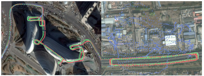
The following figure shows the performance of vehicle navigation and positioning that uses the backend fusion solution. In the figure, the GPS position is highlighted in blue, the positioning trajectory of a high-precision benchmark device is in red, and the positioning trajectory of the on-board navigation system is in green. As shown in the figure, in an underground parking lot where the GPS is obstructed or other areas with poor GPS signaling, on-board navigation positioning continuously and reliably provides high-precision position information, ensuring the reliable operation of the vehicle's navigation system.

Figure 8. Positioning performance of a parking lot Figure 9. Positioning performance with signal interference
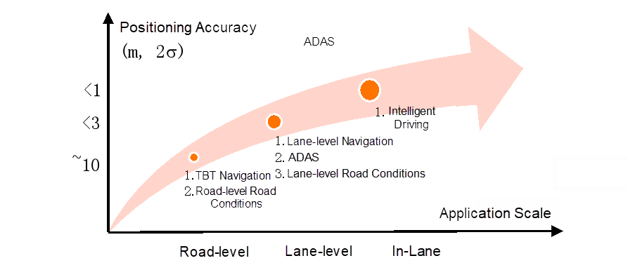
Traditional navigation positioning systems only need to solve road-level positioning problems, and the requirements for positioning accuracy are not so demanding. However, with the emergence of application scenarios such as driving assistance and automated driving, the requirements for positioning accuracy are constantly increasing, as shown in the following figure.

Figure 10. Evolution of high-precision positioning
For lane-level navigation, the positioning system must be able to distinguish the lane where the vehicle is currently located, which requires positions to be accurate to a meter or less. To ensure safety in more advanced intelligent driving applications, the position information must be accurate to several centimeters.
In order to achieve higher-precision positioning capability, our existing positioning methods must be upgraded. One way to do this is to directly upgrade the existing positioning input sources, such as upgrading the ordinary GPS to higher-precision RTK-GPS and upgrading low-cost Micro-Electro-Mechanical Systems (MEMS) inertial navigation to high-precision inertial navigation. In this way, high-precision positioning capabilities are achieved without having to modify the original algorithm framework. However, the disadvantage is that this solution does not address the defects in the original algorithm, such as the accumulated error when the GPS signal is lost for an extended period and the high cost. Another method to the preceding problem is to introduce new positioning sources, such as the lidar, millimeter-wave radar, and cameras. This requires the development of new fusion positioning algorithms for these new sensors. The following table compares different high-precision positioning solutions.
Amap cooperated with Qianxun to develop a high-precision positioning solution based on Qianxun's RTK service called Zhitu. According to road tests, this solution provides position information accurate to less than 10 centimeters under the highway and ordinary road conditions. The solution does not depend on any other sensors or map data, provides high precision in all scenarios, and can be used as a standalone high-precision positioning solution.

Figure 11. "Zhitu" high-precision positioning prototype
Among the relative positioning solutions based on environmental feature matching, lidar solutions are the most mature and reliable ones. Lidar is currently the most commonly used positioning solution in automated driving prototypes. However, due to the cost and reliability issues of lidar, there are still risks in launching mass production. Vision-based relative positioning solutions are cost-effective and have benefited from the rapid development of vision algorithms and computing chips in recent years. Such solutions have gradually become the mainstream positioning solutions for mass-produced autonomous driving products. Leveraging Amap's image and positioning capabilities, we plan to pursue high-precision positioning along three business lines.
1) System-level positioning for L3 autonomous driving: Based on the external input of visual semantic information, such as the lane line shape and type sent by Mobileye, this system matches the vehicle position with high-precision map data (HD Map) and integrates other positioning sources, such as GPS, RTK, and IMU. This enables it to calculate lane-level high-precision positioning results in real-time, while the high-precision data broadcast engine (EHP) outputs high-precision data. This system is designed to provide location and data services for autonomous driving.
2) Lane-level navigation: Based on our proprietary vision algorithms and cloud image positioning capabilities, we provide lane-level positioning capabilities for all scenarios. This will drive traditional road-level navigation to upgrade to lane-level navigation.
3) Integrated software and hardware high-precision positioning by using crowdsourced data: Based on our proprietary low-cost Vision + RTK + IMU hardware, we provide high-precision absolute positioning based on visual simultaneous localization and mapping (vSlam) technology. This provides support for high-precision data collection, reconstruction, and eventually, rapid update and iteration.
Traditional navigation and positioning are based on GPS positioning, which is only accurate to about 10 meters. Such systems are designed for different terminals, such as mobile phones and vehicles, and configured in consideration of their unique motion characteristics and input signals. In addition, they require the designing of sensor fusion algorithms, behavior judgment algorithms, and map matching algorithms in order to provide the road-level positioning accuracy required for navigation in all scenarios. As we move toward semi-automated and fully automated driving, we will need systems that provide position information accurate to the lane or even to several centimeters. This will require the upgrade of sensors and algorithms based on the considerations of actual application scenarios. We expect this to be the trajectory of the evolution of positioning technology as it enters into its next stage.
The Integration of AMAP Algorithm Engineering: Best Practices and Thoughts
amap_tech - April 20, 2020
Alibaba Clouder - June 17, 2020
Alibaba Clouder - October 15, 2018
Alibaba Clouder - April 29, 2020
Alibaba Cloud Native Community - April 17, 2025
amap_tech - March 16, 2021
 Application High Availability Service
Application High Available Service is a SaaS-based service that helps you improve the availability of your applications.
Learn More Elastic High Performance Computing Solution
High Performance Computing (HPC) and AI technology helps scientific research institutions to perform viral gene sequencing, conduct new drug research and development, and shorten the research and development cycle.
Learn More Elastic High Performance Computing
A HPCaaS cloud platform providing an all-in-one high-performance public computing service
Learn MoreMore Posts by amap_tech