This topic describes how to use IPsec-VPN to establish a secure connection between two virtual private clouds (VPCs) in dual-tunnel mode. This way, the VPCs can access each other.
Scenario
VPN gateways do not support cross-border connections. When you create an IPsec-VPN connection between two VPCs, both the VPCs must be in the Chinese mainland or outside the Chinese mainland. For more information about the regions that are in the Chinese mainland or outside the Chinese mainland, see the "Intra-border connections" section of the What is VPN Gateway? topic.
If you want to create a connection between a VPC in the Chinese mainland and a VPC outside the Chinese mainland, we recommend that you use Cloud Enterprise Network (CEN). For more information, see What is CEN?
If you create an IPsec-VPN connection between two VPCs that are in different regions, the IPsec-VPN connection quality is determined by the Internet connection quality. In this case, we recommend that you use CEN to connect the VPCs. For more information, see Connect VPCs across accounts.
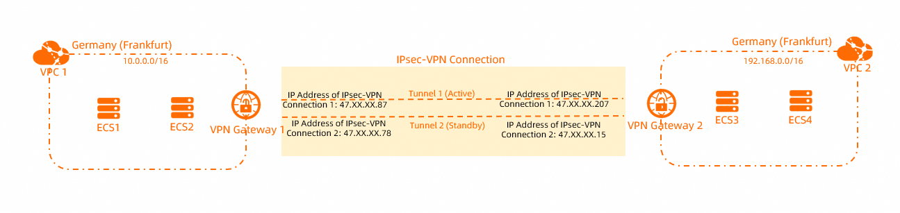
In this example, the following scenario is used: An enterprise has two VPCs (VPC1 and VPC2) in the Germany (Frankfurt) region. Elastic Compute Service (ECS) instances are deployed in the VPCs, and services are deployed on the ECS instances. Due to business development, the services in VPC1 and VPC2 need to communicate with each other.
To ensure network security, the enterprise decides to use VPN gateways to establish an IPsec-VPN connection between VPC1 and VPC2. This way, data transmission between the VPCs is encrypted and the cloud resources can communicate with each other over secure connections.
CIDR blocks
You can plan the CIDR blocks based on your business requirements. Make sure that the CIDR blocks do not overlap with each other.
VPC CIDR blocks
VPC | VPC CIDR block | ECS instance IP address |
VPC1 |
|
|
VPC2 |
|
|
BGP configurations
The following sections describe how to enable communication between the VPCs by using IPsec-VPN when static routes are configured or BGP dynamic routing is configured. The following BGP configurations are used.
If an IPsec-VPN connection uses BGP dynamic routing, the Local ASN of the two tunnels must be the same. The peer ASNs of the two tunnels can be different, but we recommend that you use the same peer ASN.
VPN gateway | IPsec-VPN connection | Tunnel | BGP ASN | BGP tunnel CIDR block | BGP IP address |
VPN Gateway 1 | IPsec-VPN Connection 1 | Active tunnel | 65530 | 169.254.10.0/30 | 169.254.10.1 |
Standby tunnel | 65530 | 169.254.20.0/30 | 169.254.20.1 | ||
VPN Gateway 2 | IPsec-VPN Connection 2 | Active tunnel | 65500 | 169.254.10.0/30 | 169.254.10.2 |
Standby tunnel | 65500 | 169.254.20.0/30 | 169.254.20.2 |
Preparations
Only the following regions and zones support the dual-tunnel mode.
VPC1 and VPC2 are created in the Germany (Frankfurt) region. ECS instances are deployed in the VPCs. Services are deployed on the ECS instances. For more information, see Create a VPC with an IPv4 CIDR block.
You understand the security group rules that apply to the ECS instances in the VPCs. Make sure that the security group rules allow the ECS instances to communicate with each other. For more information, see View security group rules and Add a security group rule.
Procedure
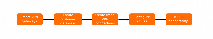
Step 1: Create VPN gateways
Log on to the VPN Gateway console.
In the top navigation bar, select the region in which you want to create the VPN gateways.
In this example, Germany (Frankfurt) is selected.
NoteThe VPN gateway must belong to the same region as the VPC that you want to associate with the VPN gateway.
On the VPN Gateways page, click Create VPN Gateway.
On the buy page, configure the following parameters, click Buy Now, and then complete the payment.
Parameter
Description
Name
Enter a name for the VPN gateway. In this example, VPN Gateway 1 is used.
Resource Group
Select the resource group to which the VPN gateway belongs. In this example, the default resource group is selected.
If you leave this parameter empty, the VPN gateway belongs to the default resource group.
Region
Select the region where you want to deploy the VPN gateway. In this example, Germany (Frankfurt) is selected.
Gateway Type
Select a gateway type. In this example, Standard is selected.
Network Type
Select a network type for the VPN gateway. In this example, Public is selected.
Tunnels
By default, Dual-tunnel is selected.
VPC
Select the VPC with which you want to associate the VPN gateway. In this example, VPC1 is selected.
vSwitch
Select a vSwitch from VPC1.
If you select Single-tunnel, you need to specify only one vSwitch.
If you select Dual-tunnel, you need to specify two vSwitches.
After the IPsec-VPN feature is enabled, the system creates an elastic network interface (ENI) for each of the two vSwitches as an interface to communicate with the VPC over an IPsec-VPN connection. Each ENI occupies one IP address in the vSwitch.
NoteThe system selects a vSwitch by default. You can change or use the default vSwitch.
After a VPN gateway is created, you cannot modify the vSwitch associated with the VPN gateway. You can view the vSwitch associated with the VPN gateway, the zone to which the vSwitch belongs, and the ENI in the vSwitch on the details page of the VPN gateway.
vSwitch 2
Select another vSwitch from VPC1.
Specify two vSwitches in different zones in the associated VPC to implement disaster recovery across zones for IPsec-VPN connections.
For a region that supports only one zone, disaster recovery across zones is not supported. We recommend that you specify two vSwitches in the zone to implement high availability of IPsec-VPN connections. You can also select the same vSwitch as the first one.
Maximum Bandwidth
Specify a maximum bandwidth value for the VPN gateway. Unit: Mbit/s.
Traffic
Select a metering method for the VPN gateway. Default value: Pay-by-data-transfer.
For more information, see Billing overview.
IPsec-VPN
Specify whether to enable IPsec-VPN. In this example, Enable is selected.
SSL-VPN
Specify whether to enable SSL-VPN. In this example, Disable is selected.
Duration
Select a billing cycle. Default value: By Hour.
Service-linked Role
Click Create Service-linked Role. The system automatically creates the service-linked role AliyunServiceRoleForVpn.
The VPN gateway assumes this role to access other cloud resources. For more information, see AliyunServiceRoleForVpn.
If Created is displayed, the service-linked role is created and you do not need to create it again.
After you create the VPN gateway, view the VPN gateway on the VPN Gateways page.
After you create a VPN gateway, it is in the Preparing state. After 1 to 5 minutes, the VPN gateway changes to the Normal state. After the VPN gateway changes to the Normal state, the VPN gateway is ready for use.
Repeat Substep 3 to Substep 4 of Step 1 to create a VPN gateway named VPN Gateway 2 in the Germany (Frankfurt) region. Associate VPC2 with VPN Gateway 2. Keep the other configurations the same as VPN Gateway 1 for VPN Gateway 2.
The following table describes the information about the VPN gateways that are created in this example.
VPN gateway
VPC
VPN gateway IP address
VPN Gateway 1
VPC1
IP address of IPsec-VPN Connection 1: 47.XX.XX.87
IP address of IPsec-VPN Connection 2: 47.XX.XX.78
VPN Gateway 2
VPC2
IP address of IPsec-VPN Connection 1: 47.XX.XX.207
IP address of IPsec-VPN Connection 2: 47.XX.XX.15
Step 2: Create customer gateways
In the navigation pane on the left, choose .
In the top navigation bar, select the region in which you want to create the customer gateways.
NoteThe customer gateway and the VPN gateway to be connected must be deployed in the same region.
On the Customer Gateway page, click Create Customer Gateway.
In the Create Customer Gateway panel, configure the following parameters and click OK.
You must create four customer gateways in the Germany (Frankfurt) region to establish VPN tunnels. The following table describes only the parameters that you must configure. You can use the default values for other parameters or leave them empty.
Parameter
Description
Germany (Frankfurt)
Germany (Frankfurt)
Germany (Frankfurt)
Germany (Frankfurt)
Name
Enter a name for the customer gateway.
For Customer Gateway 1, VPN1-Customer1 is used.
For Customer Gateway 2, VPN1-Customer2 is used.
For Customer Gateway 3, VPN2-Customer1 is used.
For Customer Gateway 4, VPN2-Customer2 is used.
IP Address
Enter the IP address of the peer gateway.
NoteIn this example, VPN Gateway 1 and VPN Gateway 2 serve as the peer gateway of each other.
In this example, the IP address of IPsec-VPN Connection 1 on VPN Gateway 2 is used, which is 47.XX.XX.207.
In this example, the IP address of IPsec-VPN Connection 2 on VPN Gateway 2 is used, which is 47.XX.XX.15.
In this example, the IP address of IPsec-VPN Connection 1 on VPN Gateway 1 is used, which is 47.XX.XX.87.
In this example, the IP address of IPsec-VPN Connection 2 on VPN Gateway 1 is used, which is 47.XX.XX.78.
ASN
Enter the ASN of the peer VPN gateway.
In this example, the BGP ASN 65500 of the active tunnel of VPN Gateway 2 is used.
In this example, the BGP ASN 65500 of the standby tunnel of VPN Gateway 2 is used.
In this example, the BGP ASN 65530 of the active tunnel of VPN Gateway 1 is used.
In this example, the BGP ASN 65530 of the standby tunnel of VPN Gateway 1 is used.
Step 3: Create IPsec-VPN connections
After you create the VPN gateways and customer gateways, you can create IPsec-VPN connections to connect the VPN gateways to the customer gateways.
In the left navigation pane, choose .
On the IPsec Connections page, click Bind VPN Gateway.
On the Create Ipsec-vpn Connection (VPN) page, configure the following parameters and click OK.
You must create two IPsec-VPN connections in the Germany (Frankfurt) region.
Parameter
Description
IPsec-VPN Connection 1
IPsec-VPN Connection 2
Name
Enter a name for the IPsec-VPN connection.
In this example, IPsec-VPN Connection 1 is used.
In this example, IPsec-VPN Connection 2 is used.
Region
Select the region where the VPN gateway to be associated with the IPsec-VPN connection is deployed.
The IPsec-VPN connection is created in the same region as the VPN gateway.
In this example, Germany (Frankfurt) is selected.
In this example, Germany (Frankfurt) is selected.
Resource Group
Select the resource group to which the VPN gateway belongs.
If you leave this parameter empty, the system displays the VPN gateways in all resource groups.
In this example, the default resource group is selected.
In this example, the default resource group is selected.
Bind VPN Gateway
Select the VPN gateway that you want to associate with the IPsec-VPN connection.
In this example, VPN Gateway 1 is selected.
In this example, VPN Gateway 2 is selected.
Routing Mode
Select a routing mode.
Note
If you want to use BGP dynamic routing for the IPsec-VPN connection, we recommend that you select Destination Routing Mode.
In this example, Destination Routing Mode is selected.
In this example, Destination Routing Mode is selected.
Effective Immediately
Select whether to immediately apply the settings of the IPsec-VPN connection. Valid values:
Yes. Start negotiations after the configuration is completed.
No. Start negotiations when inbound traffic is detected.
NoteIf you use VPN Gateway to create IPsec-VPN connections between two VPCs, we recommend that you set the Effective Immediately parameter to Yes for one of the IPsec-VPN connections. This way, IPsec negotiations can start immediately.
In this example, Yes is selected.
In this example, No is selected.
Enable BGP
If you want to use BGP routing for the IPsec-VPN connection, turn on Enable BGP. By default, Enable BGP is turned off.
In this example, Enable BGP is turned off. You can configure BGP dynamic routing after the IPsec-VPN connection is created.
In this example, Enable BGP is turned off. You can configure BGP dynamic routing after the IPsec-VPN connection is created.
Tunnel 1
Add VPN configurations for Tunnel 1.
By default, Tunnel 1 serves as the active tunnel and Tunnel 2 serves as the standby tunnel. You cannot modify this configuration.
Customer Gateway
Select the customer gateway that you want to associate with the active tunnel.
In this example, VPN1-Customer1 is selected.
In this example, VPN2-Customer1 is selected.
Pre-Shared Key
Enter a pre-shared key for the active tunnel to verify identities.
The key must be 1 to 100 characters in length, and can contain digits, letters, and the following characters:
~ ' ! @ # $ % ^ & * ( ) _ - + = { } [ ] \ | ; : ' , . < > / ?.If you do not specify a pre-shared key, the system generates a random 16-character string as the pre-shared key.
ImportantThe pre-shared key of the IPsec-VPN connection must be the same as the pre-shared key of the peer gateway device. Otherwise, the IPsec-VPN connection cannot be established.
In this example, fddsFF123**** is used.
In this example, fddsFF123**** is used.
Encryption Configuration
Configure the parameters for IKE, IPsec, dead peer detection (DPD), and NAT traversal features.
In this example, the default values are used.
In this example, the default values are used.
Tunnel 2
Add VPN configurations for Tunnel 2.
Customer Gateway
Select the customer gateway that you want to associate with the standby tunnel.
In this example, VPN1-Customer2 is selected.
In this example, VPN2-Customer2 is selected.
Pre-Shared Key
Enter a pre-shared key for the standby tunnel to verify identities.
In this example, fddsFF456**** is used.
In this example, fddsFF456**** is used.
Encryption Configuration
Configure the parameters for IKE, IPsec, DPD, and NAT traversal features.
In this example, the default values are used.
In this example, the default values are used.
In the Created message, click OK.
The following table describes the correlations among the VPCs, VPN gateways, IPsec-VPN connections, and customer gateways.
VPC
VPN gateway
IPsec-VPN connection
Tunnel
Customer gateway associated with the tunnel
VPC1
VPN Gateway 1
IPsec-VPN Connection 1
Active tunnel
VPN1-Customer1
Standby tunnel
VPN1-Customer2
VPC2
VPN Gateway 2
IPsec-VPN Connection 2
Active tunnel
VPN2-Customer1
Standby tunnel
VPN2-Customer2
Step 4: Add routes to VPN gateways
The following sections describe how to configure static routes and BGP dynamic routing for an IPsec-VPN connection in dual-tunnel mode. You need to select only one routing mode.
Add a static route
In this example, destination-based routes are used.
In the left navigation pane, choose .
In the top navigation bar, select the region where the VPN gateway instance resides.
On the VPN Gateway page, find the VPN gateway that you want to manage and click its ID.
On the Destination-based Route Table tab, click Add Route Entry.
In the Add Route Entry panel, configure the following parameters and click OK.
You need to add routes to VPN Gateway 1 and VPN Gateway 2. The following table describes the parameters.
Parameter
Description
VPN Gateway 1
VPN Gateway 2
Destination CIDR Block
Enter a destination CIDR block for the route.
In this example, the private CIDR block 192.168.0.0/16 of VPC2 is used.
In this example, the private CIDR block 10.0.0.0/16 of VPC1 is used.
Next Hop Type
Select the next hop type.
In this example, IPsec Connection is selected.
In this example, IPsec Connection is selected.
Next Hop
Select a next hop.
In this example, IPsec-VPN Connection 1 is selected.
In this example, IPsec-VPN Connection 2 is selected.
Advertise to VPC
Specify whether to advertise the route to the VPC that is associated with the VPN gateway.
In this example, Yes is selected.
In this example, Yes is selected.
Configure BGP dynamic routing
Configure BGP dynamic routing for the IPsec-VPN connection.
In the navigation pane on the left, go to .
On the IPsec Connections page, find the IPsec-VPN connection and click its ID.
In the IPsec Connections section, click Edit next to Enable BGP. In the BGP Configuration dialog box, configure the following parameters and click OK.
Configure BGP for IPsec-VPN Connection 1 and IPsec-VPN Connection 2. The following table describes the parameters.
Parameter
Description
IPsec-VPN Connection 1
IPsec-VPN Connection 2
Local ASN
Enter the ASN of the IPsec-VPN connection.
In this example, 65530 is used.
In this example, 65500 is used.
Tunnel 1
Configure BGP dynamic routing for the active tunnel.
Configure BGP dynamic routing for the active tunnel of IPsec-VPN Connection 1.
Configure BGP dynamic routing for the active tunnel of IPsec-VPN Connection 2.
Tunnel CIDR Block
Enter the CIDR block that is used by the IPsec tunnel.
The tunnel CIDR block must be a /30 CIDR block that falls within 169.254.0.0/16. The tunnel CIDR block cannot be 169.254.0.0/30, 169.254.1.0/30, 169.254.2.0/30, 169.254.3.0/30, 169.254.4.0/30, 169.254.5.0/30, 169.254.6.0/30, or 169.254.169.252/30.
NoteOn a VPN gateway, the CIDR block of each tunnel must be unique.
In this example, 169.254.10.0/30 is used.
In this example, 169.254.10.0/30 is used.
Local BGP IP address
Enter a BGP IP address for the IPsec-VPN connection.
The IP address must fall into the CIDR block of the IPsec tunnel.
In this example, 169.254.10.1 is used.
In this example, 169.254.10.2 is used.
Tunnel 2
Configure BGP dynamic routing for the standby tunnel.
Configure BGP dynamic routing for the standby tunnel of IPsec-VPN Connection 1.
Configure BGP dynamic routing for the standby tunnel of IPsec-VPN Connection 2.
Tunnel CIDR Block
Enter the CIDR block that is used by the IPsec tunnel.
The tunnel CIDR block must be a /30 CIDR block that falls within 169.254.0.0/16. The tunnel CIDR block cannot be 169.254.0.0/30, 169.254.1.0/30, 169.254.2.0/30, 169.254.3.0/30, 169.254.4.0/30, 169.254.5.0/30, 169.254.6.0/30, or 169.254.169.252/30.
NoteOn a VPN gateway, the CIDR block of each tunnel must be unique.
In this example, 169.254.20.0/30 is used.
In this example, 169.254.20.0/30 is used.
Local BGP IP address
Enter a BGP IP address for the IPsec-VPN connection.
The IP address must fall into the CIDR block of the IPsec tunnel.
In this example, 169.254.20.1 is used.
In this example, 169.254.20.2 is used.
Perform the following steps to enable automatic route advertising for VPN Gateway 1 and VPN Gateway 2.
In the navigation pane on the left, choose .
On the VPN Gateways page, find the VPN gateway, move the pointer over the
 icon, and then click Enable Automatic BGP Propagation in the Actions column.
 In the Enable Automatic BGP Propagation message, click OK.
After you configure routes, you can verify that the tunnels are available on the IPsec Connections page.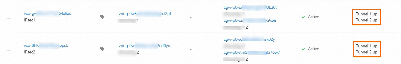
Step 5: Test the network connectivity
After you complete the preceding steps, VPC1 and VPC2 can communicate with each other. The following sections describe how to test the connectivity between VPC1 and VPC2, and test the high availability of the dual-tunnel mode.
Test the network connectivity.
Log on to ECS1 in VPC1.
For more information about how to log on to an ECS instance, see Choose a connection method.
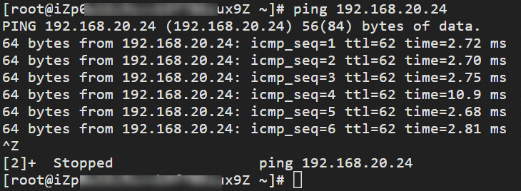
Run the ping command to ping the IP address of ECS3 in VPC2 to test the connectivity.
ping <IP address of ECS3>If you can receive echo reply packets as shown in the following figure, the VPCs can communicate with each other.
Test high availability.
Log on to ECS1 in VPC1.
For more information about how to log on to an ECS instance, see Choose a connection method.
Run the following command to keep sending packets from ECS1 to ECS3.
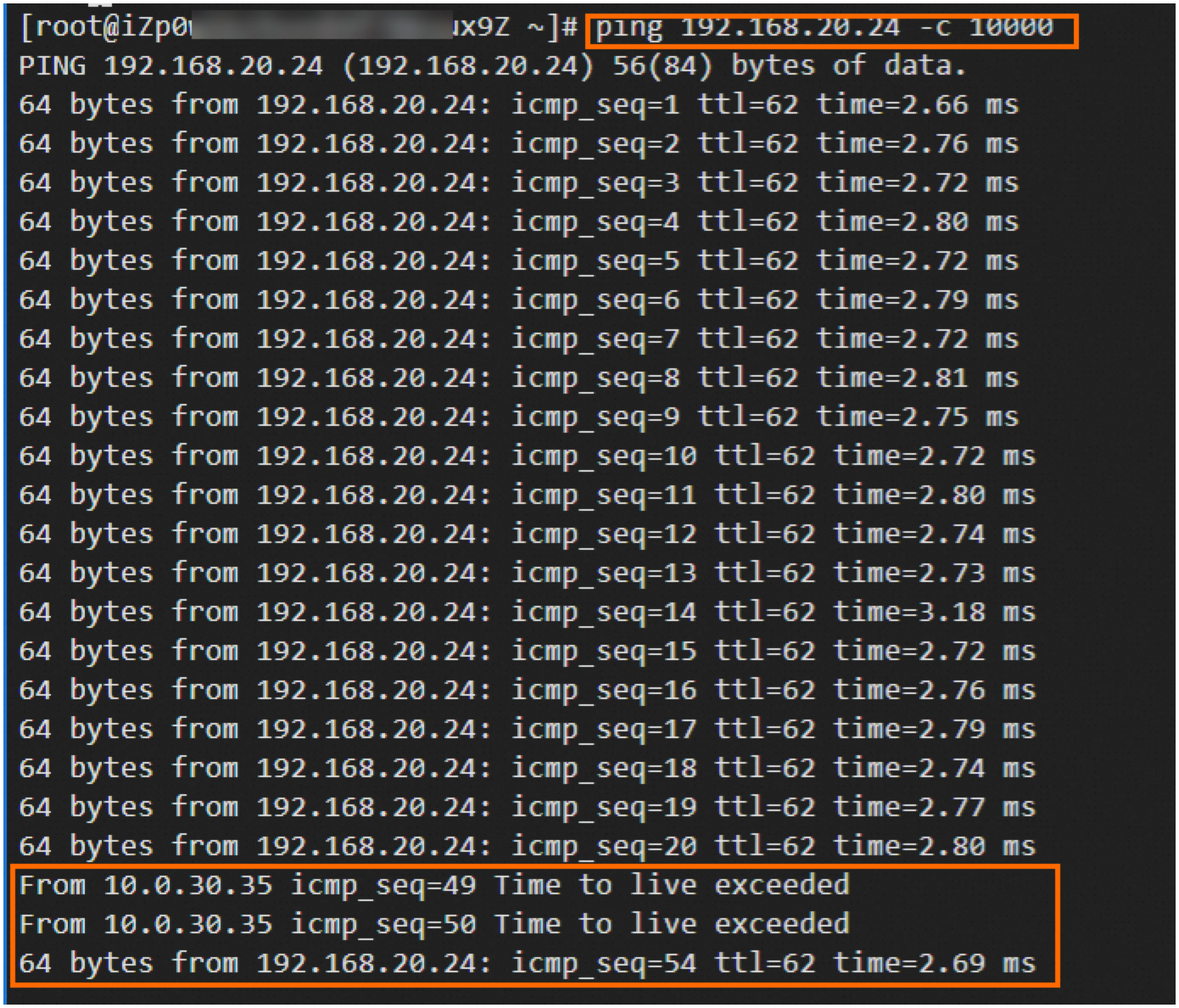
ping <IP address of ECS3> -c 10000Interrupt the active tunnel of IPsec-VPN Connection 1.
In this example, the active tunnel is interrupted by modifying the pre-shared key of the active tunnel of IPsec-VPN Connection 1. When the two ends of the active tunnel use different pre-shared keys, the active tunnel is interrupted.
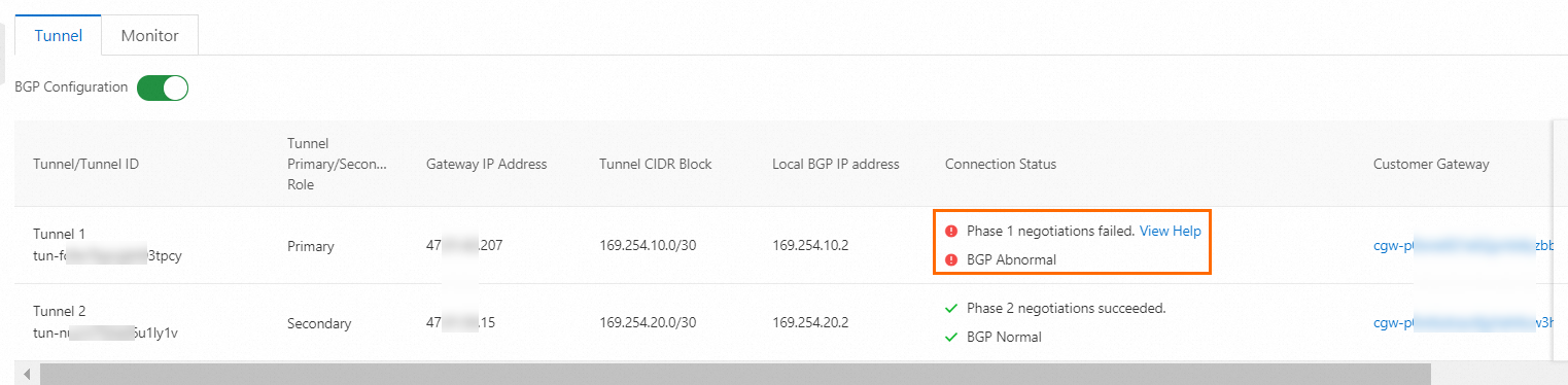
You can verify that the traffic of ECS1 is temporarily interrupted and then restored, which indicates that the standby tunnel takes over when the active tunnel is interrupted.
 Note
NoteIn scenarios where a data center communicates with a VPC by using an IPsec-VPN connection in dual-tunnel mode, after the active tunnel is interrupted, the traffic from the VPC to the data center is automatically switched to the standby tunnel. The traffic from the data center to the VPC depends on the routing configurations of the data center. If the data center does not support the switching of traffic to the standby tunnel, you can configure CloudMonitor to monitor the active tunnel. After you detect that the active tunnel is interrupted, you can manually change the routing configurations of the data center to switch traffic to the standby tunnel. For more information, see Monitor IPsec-VPN connections.