Deploy two SAG devices in one-arm mode and enable dynamic routing
This topic describes how to deploy two Smart Access Gateway (SAG) devices in one-arm mode and enable Open Shortest Path First (OSPF)-based dynamic routing to connect an on-premises network to Alibaba Cloud.
Background information
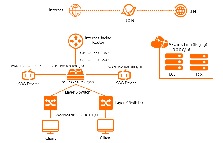
The following figure shows the topology of the on-premises network. A Layer 3 switch is connected to two Layer 2 switches. On-premises clients and servers are connected to the Layer 2 switches. Two SAG devices are connected to the Layer 3 switch in inline mode to establish network communication between the on-premises network and Alibaba Cloud. If one device is malfunctioning, the other device takes over.
Prerequisites
A virtual private cloud (VPC) is deployed in the China (Beijing) region. For more information, see Create and manage a VPC.
A Cloud Enterprise Network (CEN) instance is created and associated with the VPC in the China (Beijing) region. For more information, see Create a CEN instance.
Network planning
The following table describes the IP addresses of the network elements.
Item | IP address |
VPC in the China (Beijing) region | 10.0.0.0/16 |
Internet-facing router | 192.168.80.1/30 |
Uplink port of the Layer 3 switch | 192.168.80.2/30 |
SAG Device 1 | WAN port (port 5): 192.168.100.1/30. Next hop: 192.168.100.2. |
SAG Device 2 | WAN port (port 5): 192.168.200.1/30. Next hop: 192.168.200.2. |
Layer 3 switch |
|
On-premises network | 172.16.0.0/12 |
Step 1: Purchase SAG devices
After you purchase SAG devices in the SAG console, Alibaba Cloud delivers the devices to the specified address and creates an SAG instance to help you facilitate network management.
Log on to the SAG console.
-
In the left-side navigation pane, click SAG.
-
On the SAG page, choose .
-
Set the following parameters and click Buy Now.
-
Region: The region where you will deploy the SAG devices. In this example, select Mainland China.
-
Instance Type: The model of the SAG device. In this example, select SAG-1000.
-
Have SAG devices already: Specifies if you already own SAG hardware. In this example, select No.
-
Version: The device edition. In this example, use the default Standard Edition edition.
-
Quantity: The number of SAG devices to purchase. In this example, enter 2.
-
Region: The region where the bandwidth plan applies. This is determined by the area where the SAG devices are used and cannot be changed.
-
Instance Name: The name of the SAG instance.
The name must be 2 to 128 characters in length, and can contain letters, digits, periods (.), hyphens (-), and underscores (_). It must start with a letter.
-
Peak Bandwidth: The maximum bandwidth for communication. In this example, select 30 Mbps.
-
Subscription Period: Select a subscription duration.
-
Confirm the order information and click Confirm Purchase.
-
In the Receiving Address dialog box, enter the shipping address for the devices, and then click Buy Now.
-
On the Pay Now page, select a payment method and complete the payment.
-
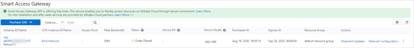
You can check whether the order is placed on the Smart Access Gateway page. SAG devices will be shipped within two business days after you place the order. To check the shipping updates, perform the following operations:
-
On the Smart Access Gateway page, find the target SAG instance.
-
In the Operation column, click the
 icon and select View Shipping Update.
 -
In the Order Updates panel, view the shipping updates.
-
Step 2: Activate the SAG devices
After you receive the SAG devices, check whether you have received all the accessories. For more information, see SAG-1000 device specifications.
Log on to the SAG console.
-
On the SAG page, find the ID of the target instance.
-
In the Operation column, click Activate.
-
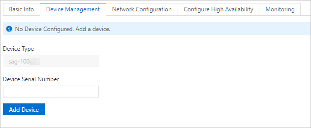
Click the ID of the target instance. On the instance details page, click the Device Settings tab and enter the serial number of the SAG device.
-
Click Add Device.
Repeat this step to associate the other SAG device with the SAG instance.
Step 3: Connect the SAG devices to your on-premises network
After you activate the SAG devices and associate them with the SAG instance, you must connect the devices to your on-premises network.
Before you begin, make sure that the devices are activated, the 4G networks work as expected, and the devices are connected to Alibaba Cloud. The active device is used in this example. Repeat this step to connect the standby device to your on-premises network.
Log on to the SAG console.
-
On the SAG page, find the ID of the target SAG instance.
-
On the instance details page, click the Device Settings tab and select the primary device.
-
In the left-side section of the tab, click Assign Port Roles.
-
On the Assign Port Roles page, find the target port and click Edit in the Operation column. Change the port role and click OK.
The WAN port (port 5) is used in this example. For more information, see Assign port roles.
Use a network cable to connect the WAN port (port 5) of the SAG device to port G11 of the Layer 3 switch.
Step 4: Configure ports
After the SAG devices are connected to your private network, you can configure the device ports in the SAG console.
The active device is used in this example. Repeat this step to configure the ports of the standby device.
Log on to the SAG console.
-
On the SAG page, click the ID of the target SAG instance.
-
On the instance details page, click the Device Settings tab.
-
In the left-side section, click Manage WAN Ports.
-
In the WAN (Port 5) section, click Edit.
-
In the Configure WAN (Port 5) panel, set the following parameters for the port and click OK.
-
Connection Type: Select Static IP.
-
IP Address: The IP address of the WAN port. In this example, enter 192.168.100.1.
-
Mask: The subnet mask for the WAN port. In this example, enter 255.255.255.252.
-
Gateway: The IP address of the gateway. In this example, enter 192.168.100.2.
NoteAfter the parameters are configured, a default route is added to the SAG device.
-
Step 5: Configure OSPF-based dynamic routing
You can configure OSPF-based dynamic routing for SAG devices in the SAG console.
The active device is used in this example. Repeat this step to configure OSPF-based dynamic routing for the standby device.
Log on to the SAG console.
-
On the SAG page, click the ID of the target SAG instance.
-
On the instance details page, click the Device Settings tab.
-
In the left-side navigation pane, click Manage Routes.
-
In the OSPF Protocol Settings section, click Edit.
-
In the Configure OSPF Protocol panel, enter the OSPF parameters as planned and click OK.
Parameter
Description
Area id
Enter the area IDs of the active and standby devices.
Area ID of the active device: 1.
Area ID of the standby device: 1.
Hello time
Set the hello time to 3 seconds for both devices.
Dead time
Set the dead time to 10 seconds for both devices.
Authentication Type
Select Disable Authentication for both devices.
Router id
Enter the router IDs of the active and standby devices.
Router ID of the active device: 192.168.100.1.
Router ID of the standby device: 192.168.200.1.
Area type
The OSPF area type. The default value is NSSA.
-
In the Dynamic Routing Settings section, select Enable OSPF Protocol.
-
For Port 5 (WAN), click Edit in the Operation column, select Enable OSPF, and then click OK.
Step 6: Configure the Layer 3 switch and Internet-facing router
The commands used to configure switches vary based on the switch provider. For more information, see the manuals issued by your providers. A switch and router provided by Cisco are used in this example.
configure the Layer 3 switch
Set the port IP addresses and OSPF parameters.
NoteFor each SAG device, the network type of ports that use the OSPF protocol must be set to peer-to-peer (P2P). Otherwise, the SAG device cannot calculate routes correctly.
interface GigabitEthernet 0/11
no switchport
ip ospf network point-to-point#Set the network type to P2P.
ip ospf hello-interval 3
ip ospf dead-interval 10
ip address 192.168.100.2 255.255.255.252#The port IP address of the peer switch of the SAG device.


interface GigabitEthernet 0/13
no switchport
ip address 192.168.200.2 255.255.255.252#The port IP address of the peer switch of Device 2.
ip ospf network point-to-point          #Set the network type to P2P.
ip ospf dead-interval 10
ip ospf hello-interval 3

!
Specify the loopback address and route advertisement information.
NoteOSPF requires an NSSA, automatically generates a default route, and advertises it to the SAG device.
interface Loopback 0
ip address 192.168.100.3 255.255.255.255 #The loopback address of the switch.
!

router ospf 1
router-id 192.168.100.3#The router ID of the switch.
network 172.16.0.0 0.15.255.255 area 0 #The CIDR block of the on-premises server.
network 192.168.100.0 0.0.0.4 area 1 #The CIDR block of the switch port connected to Device 1.
network 192.168.100.3 0.0.0.0 area 0   #The loopback IP address of the switch.
network 192.168.200.0 0.0.0.4 area 1     #The CIDR block of the switch port connected to Device 2
area 1 nssa default-information-originate no-summary

!
Configure the Internet-facing router
Add static routes

ip route 192.168.100.1 255.255.255.252 192.168.80.2 #The route to the SAG device.
ip route 192.168.200.1 255.255.255.252  192.168.80.2  #The route to Device 2.
Step 7: Set up network connections
After you configure the SAG devices, you must set up network connections to connect the on-premises network to Alibaba Cloud.
-
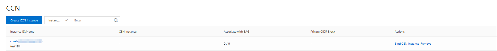
Connect the SAG instance to a CCN instance.
Log on to the SAG console.
-
In the left-side navigation pane, click CCN.
-
On the CCN page, click Create CCN Instance.
-
In the Create CCN Instance panel, enter a name for the CCN instance and click OK.
The name must be 2 to 100 characters in length, and can contain letters, digits, underscores (_), and hyphens (-).
-
Set up network connections.
Log on to the SAG console.
-
On the SAG page, click the ID of the target SAG instance, or click Network Configuration in the Operation column.
-
On the Method to Synchronize with On-premises Routes tab, select Dynamic Routing.
-
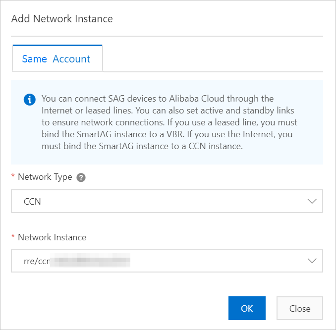
On the Network Instance Details tab, click Attach Network, select the CCN instance and the network instance, and then click OK.

-
Attach the CCN instance to a CEN instance.
Log on to the SAG console.
-
In the left-side navigation pane, click CCN.
-
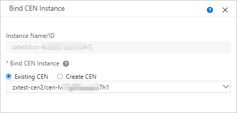
Find the target CCN instance and click Bind CEN Instance in the Operation column.
-
In the Bind CEN Instance panel, select the CEN instance that you want to bind and click OK.
After the CCN instance is attached to the CEN instance, SAG devices associated with the CCN instance can communicate with VPCs that are attached to the CEN instance.
-
Configure a security group.
Log on to the Elastic Compute Service (ECS) console.
In the left-side navigation pane, choose .
On the Security Groups page, find the security group that you want to manage and click Manage Rules in the Actions column.
-
On the security group rules page, click Add Manually.
Create a security group rule that allows access from the on-premises network to the VPC. For more information, see Add a security group rule.
Step 8: Test network connectivity
After you complete the preceding steps, access cloud resources deployed in the VPC from a client in your on-premises network to test the connectivity.