Two Smart Access Gateway (SAG) devices deployed in inline mode with static routing provide a highly available connection between your on-premises network and Alibaba Cloud.
Example scenario
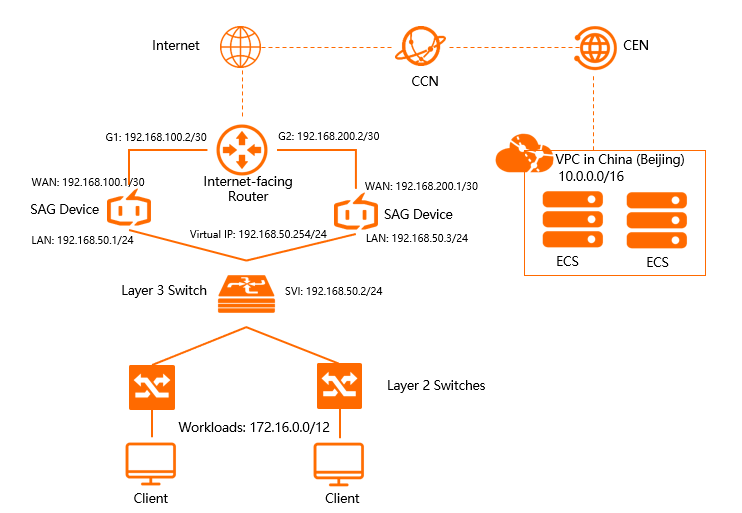
In this tutorial, a Layer-3 switch connects to two Layer-2 switches that serve on-premises clients and servers. Two SAG devices connect directly to the Layer-3 switch, providing redundant connectivity from the on-premises network to Alibaba Cloud.
Prerequisites
-
You have created a Virtual Private Cloud (VPC) in the China (Beijing) region. For more information, see Create and manage a VPC.
-
You have created a Cloud Enterprise Network (CEN) instance and attached the VPC to the CEN instance. For more information, see Create a CEN instance.
Network plan
The following table lists the network settings used in this example. If you use a different plan, ensure that the CIDR blocks of communicating networks do not overlap.
|
Item |
IP address |
|
Alibaba Cloud VPC CIDR block in the China (Beijing) region |
10.0.0.0/16 |
|
Internet-facing router addresses |
Port G1: 192.168.100.2/30 |
|
Port G2: 192.168.200.2/30 |
|
|
SAG device 1 |
|
|
SAG device 2 |
|
|
Layer-3 switch |
|
|
On-premises network |
172.16.0.0/12 |
Step 1: Purchase SAG devices
After you purchase SAG devices in the SAG console, Alibaba Cloud ships the devices to you and creates a SAG instance to manage your network configurations.
-
Log on to the Smart Access Gateway console.
On the Smart Access Gateway page, choose .
-
On the buy page, configure the SAG instance as follows, and then click Buy Now.
-
Region: The deployment area for the SAG device. In this example, select Mainland China.
-
Instance Type: The model of the SAG device. In this example, select SAG-1000.
-
Have SAG Hardware: Specify whether you already have SAG hardware. In this example, select No.
-
Version: The edition of the SAG device. In this example, the default value Standard Edition is used.
-
Quantity: The number of SAG devices to purchase. In this example, select 2.
-
Region: The area where the bandwidth is used. This must match the device's deployment area and cannot be changed.
-
Instance Name: Enter a name for the SAG instance.
The name must be 2 to 128 characters in length and start with an uppercase or lowercase letter or a Chinese character. It can contain digits, periods (.), hyphens (-), and underscores (_).
-
Peak Bandwidth: The peak bandwidth of the connection. In this example, select 30 Mbps.
-
Subscription Period: Select the subscription duration.
-
-
Review your order, and then click Confirm Purchase.
-
In the Receiving Address dialog box, enter the shipping address, and then click Buy Now.
-
On the Pay Now page, click Confirm Payment.
-
You can check whether the order is placed on the Smart Access Gateway page. SAG devices will be shipped within two business days after you place the order. To check the shipping updates, perform the following operations:
-
On the Smart Access Gateway page, find the target SAG instance.
-
In the Operation column, click the
 icon and select View Shipping Update.
 -
In the Order Updates panel, view the shipping updates.
-
After the order is placed, the status of the SAG instance is Pending Shipment.
Step 2: Activate and bind SAG devices
After receiving the SAG devices, verify that all accessories are included. For more information, see SAG-1000 device specifications.
In the top navigation bar, select the region.
-
On the Smart Access Gateway page, find the target instance.
-
In the Operation column of the target instance, click Activate.
-
Click the ID of the target instance. On the instance details page, click the Device Settings tab and enter the serial number of the SAG device.
Select a Hardware Type and click Add device.
-
Click Add Device.
-
Repeat the preceding steps to bind the second SAG device to the instance.
Step 3: Connect SAG devices
After activating and binding the SAG devices, connect them to your on-premises network as described below.
Ensure the SAG devices are powered on and have a stable 4G connection to Alibaba Cloud before you proceed. This section uses SAG device 1 as an example. Perform the same steps for SAG device 2 based on your network plan.
-
On the Smart Access Gateway page, find and click the ID of the target SAG instance.
-
On the instance details page, click the Device Settings tab.
-
In the left-side navigation pane, click Assign Port Roles.
-
On the Assign Port Roles page, find the target port, click Edit in the Operation column to change the port role, and then click OK.
In this example, the on-premises network uses WAN (Port 5) and LAN (Port 4). For more information about ports, see Assign port roles.
-
Use a network cable to connect the WAN port (Port 5) of the SAG device to port G1 of the internet-facing router.
-
Use a network cable to connect the LAN port (Port 4) of the SAG device to port G11 of the layer-3 switch.
Step 4: Configure ports
After connecting the SAG devices, configure their WAN and LAN ports in the SAG console.
This section uses SAG device 1 as an example. Perform the same steps for SAG device 2 based on your network plan.
-
Log on to the Smart Access Gateway console.
-
On the Smart Access Gateway page, click the ID of the target SAG instance.
-
On the instance details page, click the Device Settings tab.
-
In the left-side navigation pane, click LAN port management .
-
In the LAN (Port 4) section, click Edit .
-
In the Configure LAN (Port 4) dialog box, configure the port based on the following information, and then click OK .
SAG device 1:
-
Connection type : Select Static IP .
-
Interface address : The IP address of the LAN port. In this example, enter 192.168.50.1 .
-
Subnet mask : The subnet mask of the LAN port. In this example, enter 255.255.255.0 .
SAG device 2:
-
Connection type : Select Static IP .
-
Interface address : The IP address of the LAN port. In this example, enter 192.168.50.3 .
-
Subnet mask : The subnet mask of the LAN port. In this example, enter 255.255.255.0 .
-
-
In the left-side navigation pane, click Manage WAN Ports.
-
In the WAN (Port 5) section, click Edit.
-
In the Configure WAN (Port 5) dialog box, configure the port based on the following information, and then click OK.
SAG device 1:
-
Connection Type: Select Static IP.
-
IP Address: The IP address of the WAN port. In this example, enter 192.168.100.1.
-
Mask: The subnet mask of the WAN port. In this example, enter 255.255.255.252.
-
Gateway : The IP address of the gateway. In this example, enter 192.168.100.2.
SAG device 2:
-
Connection Type: Select Static IP.
-
IP Address: The IP address of the WAN port. In this example, enter 192.168.200.1.
-
Mask: The subnet mask of the WAN port. In this example, enter 255.255.255.252.
-
Gateway: The IP address of the gateway. In this example, enter 192.168.200.2.
NoteAfter you configure the gateway, the SAG device automatically adds a default route.
-
Step 5: Configure routing
After configuring the WAN and LAN ports, configure route synchronization to advertise on-premises routes to the cloud and add a static route for cloud-to-on-premises traffic.
This section uses SAG device 1 as an example. Perform the same steps to configure SAG device 2 based on your network plan.
-
On the Smart Access Gateway page, click the ID of the target SAG instance.
-
On the instance details page, click the Network Configuration tab.
-
In the left-side navigation pane, click Method to Synchronize with On-premises Routes.
-
Select Static Routing, click Add Static Route, configure the static route, and then click OK.
Add a static route for the on-premises network CIDR block: 172.16.0.0/12.
-
On the same instance page, click the Device Settings tab.
-
In the left-side navigation pane, click Manage Routes, and then click Add Static Route.
-
On the Add Static Route page, add a static route that directs traffic to the on-premises network.
Parameter
Description
Destination CIDR block
SAG device 1: 172.16.0.0/12
SAG device 2: 172.16.0.0/12
Next hop IP
SAG device 1: 192.168.50.2
SAG device 2: 192.168.50.2
Port
For both SAG devices, select Port 4 (LAN).
Step 6: Configure HA
Configure HA to provide redundancy and prevent single points of failure.
This section uses SAG device 1 as an example. Perform the same steps to configure SAG device 2 based on your network plan.
- Log on to the Smart Access Gateway console.
-
Navigate to the Device Settings page using one of the following methods.
-
Click the ID of the target SAG instance. On the instance details page, click Device Settings.
-
Find the target SAG instance and choose
 > Device Settings from the Operation column.
-
-
On the Device Settings page, click Manage HA.
-
In the HA Information section, click the
 icon.
icon. -
On the HA Settings page, select an HA mode.
The following table describes the parameters.
Configuration
Description
HA Mode
Select Static for both SAG devices.
Port
Select Port 4 (LAN) for both devices.
Virtual IP
The virtual IP address used for HA. In this example, set this to 192.168.50.254 for both SAG devices.
-
Click Save.
Step 7: Configure layer-3 switch and router
Configuration commands vary by switch vendor. The following commands are for reference only. Refer to your device documentation for detailed instructions.
-
Switch configuration
Configure port IP addresses: interface GigabitEthernet 0/12 switchport access vlan 10 //Assign the port connected to the LAN port of SAG device 1 to VLAN 10. interface GigabitEthernet 0/14 switchport access vlan 10 //Assign the port connected to the LAN port of SAG device 2 to VLAN 10. interface vlan 10 ip address 192.168.50.2 255.255.255.0 //Client gateway address ip route 0.0.0.0 0.0.0.0 192.168.50.254 //The route from the switch to the internet. -
Internet-facing router configuration
Configure static routes:
ip route 192.168.100.1 255.255.255.252  192.168.100.2  //The route from the internet-facing router to SAG device 1.
ip route 192.168.200.1 255.255.255.252  192.168.200.2  //The route from the internet-facing router to SAG device 2.
Step 8: Configure network connections
After configuring the SAG devices, set up network connections between your on-premises network and Alibaba Cloud.
-
Create a Cloud Connect Network (CCN) instance.
-
Log on to the Smart Access Gateway console.
-
In the left-side navigation pane, click CCN.
-
On the CCN page, click Create CCN Instance.
-
In the Create CCN Instance pane, enter a name for the CCN instance and click OK.
The name must be 2 to 100 characters in length and start with a letter or a Chinese character. It can contain digits, underscores (_), and hyphens (-). After the CCN instance is created, you can view it on the CCN instance list. The instance ID starts with
ccn-. At this point, the instance is not yet bound to a CEN or SAG instance. In the Actions column, click Bind CEN to proceed.
-
-
Configure network connections.
-
Log on to the Smart Access Gateway console.
-
On the SAG page, find the SAG instance for which you want to configure the network and click Network Configuration in the Operation column.
-
On the Network Instance Details tab, click Add Network. In the dialog box, select the CCN instance that you created, and then click OK.
-
-
Bind a CEN instance.
-
Log on to the Smart Access Gateway console.
-
In the left-side navigation pane, click CCN.
-
Find the CCN instance that you want to bind to a CEN instance and click Bind CEN Instance in the Operation column.
-
In the Bind CEN Instance pane, select the CEN instance that you want to bind, and then click OK.
After binding, the SAG devices in the CCN instance can communicate with network instances attached to the CEN instance, such as VPCs and Virtual Border Routers (VBRs). The dialog box offers two options: Select existing CEN and Create new CEN. Select Select existing CEN and choose the target CEN instance from the drop-down list.
-
-
Configure a security group.
Add a security group rule that allows your on-premises network to access resources in the VPC. For more information, see Add a security group rule.
Step 9: Test connection
After completing all configurations, access cloud resources in the VPC from an on-premises client to verify connectivity.