MaxCompute builds a data lakehouse architecture that supports Delta Lake and Apache Hudi storage mechanisms based on Alibaba Cloud services Data Lake Formation (DLF), ApsaraDB RDS, Realtime Compute for Apache Flink, and Object Storage Service (OSS). Delta Lake and Hudi are commonly used storage mechanisms in data lake solutions, providing stream processing and batch processing capabilities for data lakes. You can query real-time data through MaxCompute to get timely insights into business data changes.
Background information
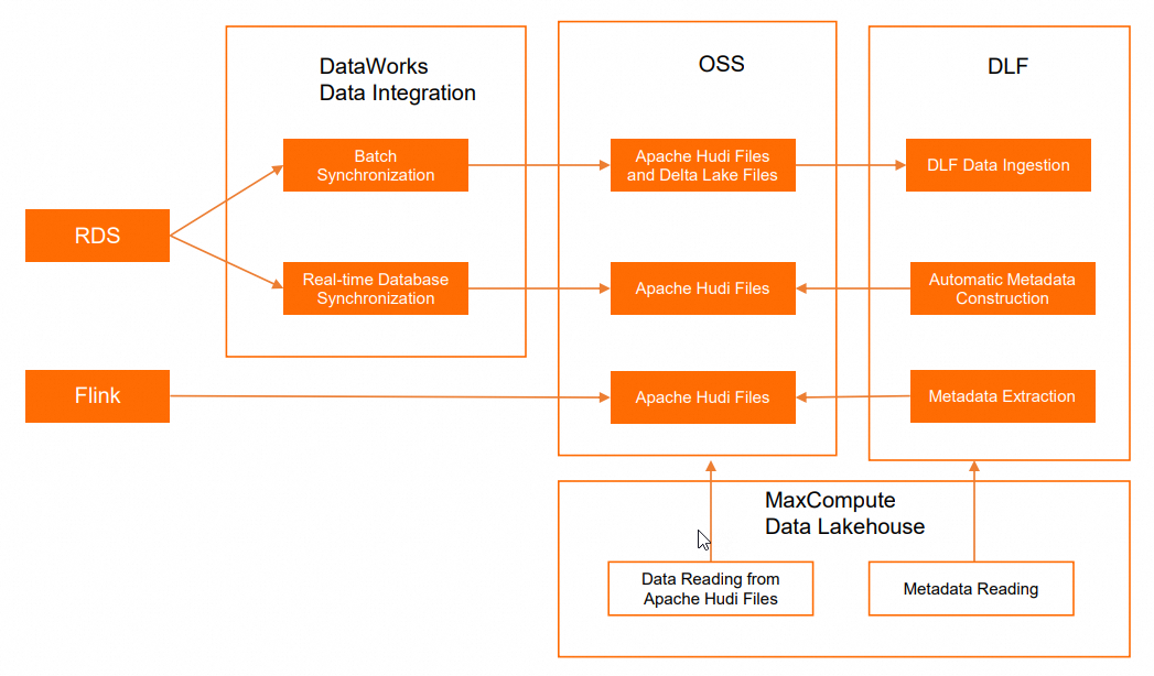
In most cases, the process of creating and applying data lakes involves data ingestion, data lake storage and management, and data exploration and analysis. MaxCompute provides a data lakehouse solution that supports Delta Lake and Apache Hudi. This solution is developed based on Alibaba Cloud services DLF, ApsaraDB RDS or Realtime Compute for Apache Flink, and OSS. The following figure shows the architecture of such a data lakehouse solution.
Operation | Alibaba Cloud service | Description |
Online database operations | Serves as a data source of data lakes. | |
Real-time computing | Serves as a data source of data lakes. | |
Data ingestion | Connects to ApsaraDB RDS and manages the data source of data lakes. | |
Data lake storage and management | When data in ApsaraDB RDS databases is ingested into data lakes, OSS is used as the data store for the data lakes. The Delta Lake and Apache Hudi storage mechanisms are supported. DLF uses the metadata management feature to manage metadatabases and metadata tables. | |
Data lake exploration and analysis |
| Analyzes data in data lakes. |
Prerequisites
The following conditions are met:
Data Transmission Service (DTS) is activated.
You can perform one-click authorization on the Cloud Resource Access Authorization page in the Resource Access Management (RAM) console. After you assign the AliyunDTSDefaultRole role to the Alibaba Cloud account for your MaxCompute project, the DTS service is activated.
An ApsaraDB RDS for MySQL instance or a fully managed Flink instance is created.
If you want to implement the data lakehouse solution that supports the Delta Lake or Apache Hudi storage mechanism based on DLF, ApsaraDB RDS for MySQL, and OSS, you must create an ApsaraDB RDS for MySQL instance.
If you want to implement the data lakehouse solution that supports the Apache Hudi storage mechanism based on DLF, Realtime Compute for Apache Flink, and OSS, you must create a fully managed Flink instance. For more information about how to create a fully managed Flink instance, see Activate fully managed Flink.
DLF is activated.
A MaxCompute project is created. This project is not an external project.
The following example shows a MaxCompute project named
doc_test_prodthat belongs to the China (Shanghai) region.
Limits
The data lakehouse solution based on the Delta Lake or Apache Hudi storage mechanism has the following limits:
The data lakehouse solution is supported in the China (Hangzhou), China (Shanghai), China (Beijing), China (Zhangjiakou), China (Shenzhen), China (Hong Kong), Singapore, and Germany (Frankfurt) regions.
MaxCompute must be deployed in the same region as DLF, OSS, and ApsaraDB RDS or Realtime Compute for Apache Flink.
MaxCompute allows you to read all columns in Apache Hudi or Delta Lake files. Operations such as incremental data reads, snapshot reads, and data writes are not supported.
Delta Lake or Apache Hudi storage mechanism based on DLF, ApsaraDB RDS, and OSS
Procedure
Step 1: Grant MaxCompute the permissions to access DLF and OSS
Grant the access permissions on DLF and OSS to the Alibaba Cloud account that manages the MaxCompute project.
Step 2: Create a bucket and a folder in OSS
Create an OSS bucket as the unified storage path for data lakes.
Step 3: Prepare the data that you want to ingest into data lakes
Create an ApsaraDB RDS database and prepare the data that you want to ingest into data lakes.
Step 4: Add a data source to DLF and create a metadatabase
Add ApsaraDB RDS as a data source for DLF.
Step 5: Create and start a data ingestion task in the DLF console
Create a data ingestion task in the DLF console to synchronize table data from the ApsaraDB RDS database and play back the data to a data lake in real time.
Step 6: Analyze data in a data lake based on MaxCompute
Create an external project on the Lake and Warehouse Integration (Data Lakehouse) page in the DataWorks console to analyze data in a data lake.
Step 1: Grant MaxCompute the permissions to access DLF and OSS
The Alibaba Cloud account that manages the MaxCompute project cannot access DLF or OSS without authorization. You can use one of the following methods to authorize the Alibaba Cloud account:
One-click authorization: If you use the same account to create the MaxCompute project and deploy DLF and OSS, we recommend that you perform one-click authorization on the Cloud Resource Access Authorization page in the Resource Access Management (RAM) console.
Custom authorization: You can use this method regardless of whether the same account is used to create the MaxCompute project and deploy DLF and OSS. For more information, see Authorize a RAM user to access DLF.
Step 2: Create a bucket and a folder in OSS
Create an OSS bucket as the unified storage path for data lakes.
Log on to the OSS console.
In the left-side navigation pane, click Buckets. On the Buckets page, click Create Bucket.
In the Create Bucket panel, configure the Bucket Name parameter, select a region, and then click Create. For example, you can set the Bucket Name parameter to
mc-dlf-ossand select theChina (Shanghai)region from the Region drop-down list.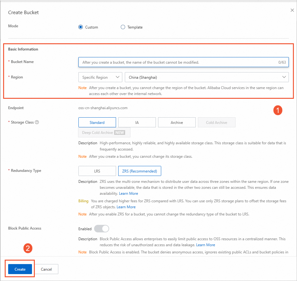
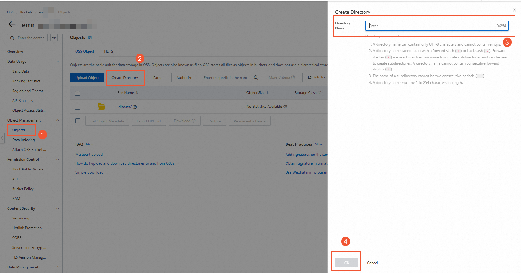
On the Buckets page, click the name of the created bucket to go to the Objects page.
On the right side of the page, click Create Directory. In the Create Directory panel, specify Directory Name, such as datalaketest, and click OK.
Step 3: Prepare the data that you want to ingest into data lakes
Construct an ApsaraDB RDS database, create a table, and prepare the data that you want to ingest into data lakes.
Go to the Instances page in the ApsaraDB RDS console. In the top navigation bar, select a region, such as
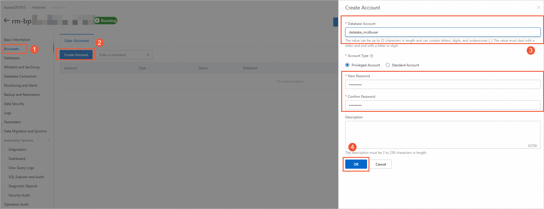
China (Shanghai). Then, click the ID of the instance that you want to use in the instance list. In this example, an ApsaraDB RDS for MySQL instance is used.Create an ApsaraDB RDS database account. In the left-side navigation pane of the instance details page, click Accounts. On the User Account tab, click Create Account. In the Create Account panel, configure the parameters and click OK. The following table describes the parameters.
Parameter
Description
Example
Database Account
The account that is used to access the ApsaraDB RDS database. This information is associated with the ApsaraDB RDS database when you create the database.
datalake_mcdbuser
Account Type
The type of the account. Valid values:
Standard Account: You must associate this account with the ApsaraDB RDS database.
Privileged Account: This account has permissions on all databases in the ApsaraDB RDS instance. You do not need to grant permissions on specific databases to the privileged account.
Standard Account
New Password
The password of the account.
None
Confirm Password
Confirm the password of the account.
None
For more information about the parameters, see Create databases and accounts for an ApsaraDB RDS for MySQL instance.
Create an ApsaraDB RDS database. In the left-side navigation pane of the instance details page, click Databases. On the right side of the page, click Create Database. In the Create Database panel, configure the parameters and click Create. The following table describes the parameters.
Parameter
Description
Database Name
The name must be 2 to 64 characters in length.
It must start with a letter and end with a letter or digit.
It can consist of lowercase letters, digits, underscores (_), or hyphens (-).
The database name must be unique within the instance.
NoteIf the database name contains a hyphen (
-), the corresponding folder name for the created database will replace the hyphen (-) with@002d.Supported Character Set
Select a character set as needed.
Authorized By
Select the account that needs to access this database. This parameter can be left empty, and accounts can be bound after the database is created. For more information, see Modify account permissions.
NoteOnly regular accounts are displayed here because high-privilege accounts automatically have all permissions for all databases and do not require authorization.
Description
Optional. This parameter is used to add remarks about the database for easier subsequent database management. Up to 256 characters are allowed.
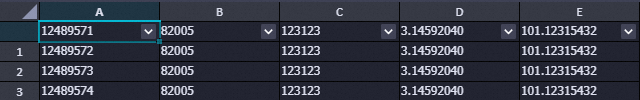
Create a table in the ApsaraDB RDS database and insert a small amount of test data into the table. For more information, see Use DMS to log on to an ApsaraDB RDS for MySQL instance. In this example, a table named anti_fraud_result is created. Sample statements:
CREATE TABLE `anti_fraud_result` (
  `transactionid` varchar(32) NOT NULL,
  `uid` varchar(32) DEFAULT NULL,
  `card` varchar(32) DEFAULT NULL,
  `longitude` double(12,8) DEFAULT '12.00000000',
  `latitude` double(12,8) DEFAULT '12.00000000',
  PRIMARY KEY (`transactionid`)
) ENGINE=InnoDB DEFAULT CHARSET=utf8
;

INSERT INTO `anti_fraud_result` values ("12489571","82005","123123",3.14592040,101.12315432);
INSERT INTO `anti_fraud_result` values ("12489572","82005","123123",3.14592040,101.12315432);
INSERT INTO `anti_fraud_result` values ("12489573","82005","123123",3.14592040,101.12315432);
INSERT INTO `anti_fraud_result` values ("12489574","82005","123123",3.14592040,101.12315432);
(Optional) Step 4: Add a data source to DLF and create a metadatabase
This step is required if you want to use single-table batch synchronization in Step 5: Create and start a data ingestion task in the DLF console. If you want to use real-time database synchronization, skip this step.
Create a metadatabase to manage data of data lakes in DLF.
Log on to the DLF console. In the top navigation bar, select a region, such as
China (Shanghai).Create a metadatabase, such as the datalake metadatabase.
In the left-side navigation pane of the DLF console, choose > Metadata. On the Database tab of the Metadata page, click Create Database.
On the Create Database page, configure the parameters. The following table describes the parameters.
Parameter
Description
Example
Catalog
The name of the database catalog where the data is stored.
default
Database Name
The name of the destination metadatabase.
dlf_db
Database Description
The description of the metadatabase that you want to create.
Data lakehouse
Select Path
The OSS directory in which the data file is saved. The directory must be in the
oss://<Bucket name>/<OSS directory name>format.oss://doc-test-01/datalake/
Click OK.
Step 5: Create and start a data ingestion task in the DLF console
The data ingestion feature of DLF is no longer updated. You can use one of the following methods to ingest data into data lakes as Delta Lake files or Apache Hudi files.
You can select the single-table batch synchronization solution for ingesting data as Delta Lake files.
We recommend that you select the real-time database synchronization solution for ingesting data as Apache Hudi files. You can also use the single-table batch synchronization solution for ingesting data as non-partitioned Apache Hudi files. You do not need to create a batch synchronization task on the DataStudio page in the DataWorks console. You can directly create a task for injecting all data from relational databases into a data lake. For more information, see the format conversion of OSS data description in this topic.
Single-table batch synchronization
On the DataStudio page in the DataWorks console, create a batch synchronization task to ingest data into the data lake.
create a batch synchronization task.
Prepare an ApsaraDB RDS for MySQL data source.
Configure an ApsaraDB RDS for MySQL in DataWorks. For more information, see Add a MySQL data source.
Prepare an OSS data source.
Configure an OSS data source in DataWorks. For more information, see Add an OSS data source.
Create and run a data synchronization task.
On the DataStudio page in the DataWorks console, create a batch synchronization task. For more information, see Configure a batch synchronization task by using the codeless UI. The following content describes the key parameters that you must configure.
Configure network connections and resource groups.

Parameter
Description
Source
Source
Select MySQL.
Data Source Name
Select the name of the ApsaraDB RDS for MySQL data source that you created.
Resource Group
Resource Group
Select the exclusive resource group for Data Integration.
Destination
Destination
Select OSS.
Data Source Name
Select the created OSS data source.
Configure a task.
In the Configure tasks step, specify the Table and File name (including path) parameters.
Parameter
Description
Table
Select the name of the table that is created in the ApsaraDB RDS database.
File name (including path)
The file name must be in the <File directory created in OSS>/<Name of the data file to be exported to OSS> format.
Example:
doc-test-01/datalake/anti.csv.Click the
 icon in the upper-left corner of the configuration page of the batch synchronization task to save the configuration, and then click the
  icon to run the task.
 After the task is successfully run in DataWorks, you can check whether the data is imported to the OSS directory.
Convert the format of OSS data and ingest the data into the data lake.
Log on to the DLF console. In the top navigation bar, select a region.
In the left-side navigation pane, choose Data Ingestion > Ingestion Tasks.
On the Data Ingestion Tasks page, click Create Ingestion Task. On the page that appears, select OSS Data Format Conversion, and then click Next.
NoteIf you want to convert the data format to Apache Hudi, set Task Type to RDS Full Data Ingestion.
On the page that appears, configure the parameters that are described in the following table, retain the default values of other parameters, and then click OK.
OSS Data Format Conversion
Section
Parameter
Description
Example
Configure Data Source
OSS Storage Path
The OSS directory where the data source is stored. The directory must be in the
oss://<Bucket name>/<OSS directory name>/format.oss:/doc-test-01/datalake/
Storage Format
The data format of the source table.
CSV
Configure Destination Data Lake
Destination database
The database that stores the destination table.
datalake
Destination Table Name
The name of the table that you create for your job.
anti_rds
Storage Format
The data format of the destination table.
Delta
Data Lake Storage Location
The OSS directory where the data is stored. The directory must be in the
oss://<Bucket name>/<OSS directory name>/format.oss:/doc-test-01/dlf/
Configure Task Information
Task Instance Name
The name of the data ingestion task.
Delta Format Conversion for OSS Data Ingestion
Maximum Resource Parallelism
The maximum number of worker nodes that can run at the same time. DLF starts worker nodes to complete data ingestion.
20
RDS Full Data Ingestion
Section
Parameter
Description
Example
Configure Data Source
Data Sources
Displays RDS instances in the same region and under the same account. You can select the target data source from the drop-down list.
None
Table Path
The path of the source table to be synchronized. Format:
<database_name>/<table_name>.None
Configure Destination Data Lake
Destination database
The database that stores the destination table.
database_1
Destination Table Name
The name of the table that you create for your job.
anti_rds
Storage Format
The data format of the destination table.
Hudi
Data Lake Storage Location
The OSS directory where the data is stored. The directory must be in the
oss://<Bucket name>/<OSS directory name>/format.oss:/doc-test-01/dlf/
Partition Information
You can add partitions. The data that is written to the data lake is used as a partition.
None
Configure Task Information
Task Instance Name
The name of the data ingestion task.
Ingestion of Full Data in Apache Hudi Fomat in Relational Databases
Maximum Resource Parallelism
The maximum number of worker nodes that can run at the same time. DLF starts worker nodes to complete data ingestion.
20
On the Data Ingestion Tasks page in the DLF console, find the task that you created, click Run in the Actions column, and then click OK to start the task.
When the progress of the task reaches 100%, the OSS data format is converted.
Click the Database tab on the Metadata page, and click the name of the destination database. On the Table List tab, check whether the table is created.
Real-time database synchronization
In the Data Integration module of DataWorks, create a real-time database synchronization task to ingest data in the Apache Hudi format into the data lake. For more information, see Synchronize all data in a MySQL database to a data lake in OSS in real time. The following content describes the key parameters that you must configure.
Prepare an ApsaraDB RDS for MySQL data source.
Configure an ApsaraDB RDS for MySQL in DataWorks. For more information, see Add a MySQL data source.
Prepare an OSS data source.
Configure an OSS data source in DataWorks. For more information, see Add an OSS data source.
On the page for the synchronization task, configure the following parameters.
Configure network connections and resource groups.
Parameter
Description
Source
Source
Select MySQL.
Data Source Name
Select the name of the ApsaraDB RDS for MySQL data source that you created.
Resource Group
Resource Group for Data Synchronization
Select the exclusive resource group for Data Integration.
Destination
Destination
Select OSS.
Data Source Name
Select the created OSS data source.
Select the tables from which you want to synchronize data.
On the left side of the configuration page that appears, you can specify a filter condition to search for databases and tables from which you want to synchronize data.
On the right side of the configuration page that appears, you can preview the databases and tables from which you want to synchronize data.
You can refer to the following instructions to quickly select the desired databases and tables based on the number of source databases and tables:
If you want to synchronize data from only a small number of databases and tables, you can manually select the desired databases and tables when you preview the source databases and tables and move the databases and tables to the selected databases and tables. Then, the system automatically adds a filter condition on the left side of the configuration page.
If you want to synchronize data from multiple sources, source databases, and source tables, you can manually specify a filter condition to search for the databases and tables from which you want to synchronize data. You can also specify a keyword in the search box on the right side of the configuration page to search for the desired databases and tables and add or remove databases and tables.
Configure the data ingestion task.
OSS Storage Path: Select the OSS path in which you want to store the synchronized data.
Location For Creating Metadatabase: Select DLF.
Prefix For Metadatabase Name: The system automatically creates a metadatabase based on the name of the source database. You can manually specify a prefix for the name of the metadatabase. The specified prefix is automatically added to the metadatabases and metatables that are created.
Data Lake Format: Select Hudi.
Partition Information
The following variables are supported: ${yyyy}, ${MM}, ${dd}, and ${HH}. The time can be accurate only to the hour.
Variables can be concatenated with strings. For example, you can concatenate variables by using underscores (_) to form a string, such as ${yyyy}_${MM}_${dd}_${HH}.
You can specify multiple levels of partitions. This way, data can be written to a table that contains multiple levels of partitions. The levels of partitions must be consistent with the order of partitions that you specify.
You can specify the partitions in which you want to store the synchronized data. When the synchronization task is run, the synchronized data is stored in the related partition based on the time when the data is written to OSS. When you specify partitions, take note of the following items:
Click Complete, and click OK.
Find the synchronization task that you created, and click Start in the Actions column. Then, view the task status.
After the synchronization task succeeds, log on to the DLF console, and choose Metadata > Metadata in the left-side navigation pane. On the Metadata page, click the name of the newly generated database. On the Table List tab, view the generated tables.
Step 6: Analyze data in a data lake based on MaxCompute
You can create an external project based on the created MaxCompute project, DLF metadatabase, and OSS bucket. This external project is mapped to the MaxCompute project and associates MaxCompute with OSS and DLF. Then, you can use the MaxCompute project to analyze the data of the external project. Only the owner of the MaxCompute project or users who are assigned the Admin or Super_Administrator role can create an external project.
You can assign the tenant-level Super_Administrator role to a user on the Users tab of the MaxCompute console. Only the Alibaba Cloud account or a RAM user that is assigned the tenant-level Super_Administrator role can assign roles to users. For more information, see the "Assign a role to a user" section in Perform access control based on project-level roles.
Create an external project in the DataWorks console.
Log on to the DataWorks console. In the top navigation bar, select the China (Shanghai) region.
In the left-side navigation pane of the DataWorks console, choose .
On the Lake and Warehouse Integration (Data Lakehouse) page, click Start.
On the Create Data Lakehouse page, configure the parameters. The following tables describe the parameters.
Table 1. Parameters in the Create Data Warehouse step
Parameter
Description
External Project Name
ext_dlf_delta
MaxCompute Project
ms_proj1
Table 2. Parameters in the Create Data Lake Connection step
Parameter
Description
Heterogeneous Data Platform Type
Select Alibaba Cloud DLF + OSS from the drop-down list.
None
Alibaba Cloud DLF + OSS
External Project Description
None
Region Where DLF Is Activated
cn-shanghai
DLF Endpoint
dlf-share.cn-shanghai.aliyuncs.com
DLF Database Name
datalake
DLF RoleARN
None
Click Create. On the page that appears, click Preview.
If you can preview the table information in the DLF database, the operation is successful.
NoteThis step describes how to create an external project in the DataWorks console. For more information about how to create an external project by using SQL statements, see Use SQL statements to manage an external project.
On the Ad Hoc Query page of the DataWorks console, view the tables in the external project.
Sample statement:
show tables in ext_dlf_delta;The following result is returned:
ALIYUN$***@aliyun.com:anti_rdsNoteFor more information about the ad hoc query feature that is provided by DataStudio of DataWorks, see Use an ad hoc query node to execute SQL statements (Optional).
On the Ad Hoc Query page of the DataWorks console, query the table data of the external project.
NoteIf the query result is garbled, resolve the issue by following instructions in the section "How do I handle a dirty data error that is caused by encoding format configuration issues or garbled characters?" in Batch synchronization.
Sample statement:
select * from ext_dlf_delta.anti_rds;The following figure shows the returned result.
Apache Hudi storage mechanism based on DLF, Realtime Compute for Apache Flink, and OSS
Procedure
Step 1: Grant MaxCompute the permissions to access DLF and OSS
Grant the DLF and OSS access permissions to the Alibaba Cloud account that manages the MaxCompute project.
Step 2: Create a bucket and a folder in OSS
Create an OSS bucket as the unified storage path for data lakes.
Step 3: Prepare the data that you want to ingest into data lakes
Create temporary tables and prepare the data that you want to ingest into data lakes in the Realtime Compute for Apache Flink console.
Step 4: Add a data source to DLF and create a metadatabase
Add a data source to DLF and create a metadatabase.
Step 5: Create and start a metadata extraction task in the DLF console
Create a metadata extraction task in the DLF console to extract table data in the OSS directory into the data lake.
Step 6: Analyze data in a data lake based on MaxCompute
Create an external project on the Lake and Warehouse Integration (Data Lakehouse) page in the DataWorks console to analyze data in a data lake.
Step 1: Grant MaxCompute the permissions to access DLF and OSS
The Alibaba Cloud account that manages the MaxCompute project cannot access DLF or OSS without authorization. You can use one of the following methods to authorize the Alibaba Cloud account:
One-click authorization: If you use the same account to create the MaxCompute project and deploy DLF and OSS, we recommend that you perform one-click authorization on the Cloud Resource Access Authorization page in the Resource Access Management (RAM) console.
Custom authorization: You can use this method regardless of whether the same account is used to create the MaxCompute project and deploy DLF and OSS. For more information, see Authorize a RAM user to access DLF.
Step 2: Create a bucket and a folder in OSS
Create an OSS bucket as the unified storage path for data lakes.
Log on to the OSS console.
In the left-side navigation pane, click Buckets. On the Buckets page, click Create Bucket.
In the Create Bucket panel, configure the Bucket Name parameter, select a region, and then click Create. For example, you can set the Bucket Name parameter to
mc-dlf-ossand select theChina (Shanghai)region from the Region drop-down list.On the Buckets page, click the name of the created bucket to go to the Objects page.
On the right side of the page, click Create Directory. In the Create Directory panel, specify Directory Name, such as datalaketest, and click OK.
Step 3: Prepare the data that you want to ingest into data lakes
Use the Hudi connector to create temporary tables and prepare the data that you want to ingest into data lakes in the Realtime Compute for Apache Flink console. For more information, see Get started with an SQL deployment.
Go to the instance list in the Realtime Compute for Apache Flink console. In the top navigation bar, select the region where the Realtime Compute for Apache Flink instance is located. Then, click the ID of instance.
In the left-side navigation pane, choose . Then, click New to create a blank stream draft, and click Next.
In the New Draft dialog box, specify the job information and click Create.
Enter the following statements in the SQL editor. For more information about the syntax, see Hudi connector (to be retired).
-- Create a temporary table named datagen as the data source.
CREATE TEMPORARY TABLE datagen(
  id INT NOT NULL PRIMARY KEY NOT ENFORCED,
  data  STRING,
  ts TIMESTAMP(3)
) WITH (
  'connector' = 'datagen' ,
  'rows-per-second'='100'
);

-- Create a temporary table named flink_hudi_tbl as the result table. The data store points to OSS and the data is stored in the Apache Hudi format.
CREATE TEMPORARY TABLE flink_hudi_tbl (
  id INT NOT NULL PRIMARY KEY NOT ENFORCED,
  data STRING,
  ts TIMESTAMP(3)
) WITH (
  'connector' = 'hudi',
  'oss.endpoint' = 'oss-cn-beijing-internal.aliyuncs.com',
  'accessKeyId' = '${secret_values.ak_id}',
  'accessKeySecret' = '${secret_values.ak_secret}',
  'path' = 'oss://<yourOSSBucket>/<Custom storage location>',
  'table.type' = 'MERGE_ON_READ',
  'hive_sync.enable' = 'true',
  'hive_sync.mode' = 'hms',
  'hive_sync.db' = 'flink_hudi',
  'hive_sync.table' = 'flink_hudi_tbl',
  'dlf.catalog.region' = 'cn-beijing',
  'dlf.catalog.endpoint' = 'dlf-vpc.cn-beijing.aliyuncs.com'
);

-- Write data from the source table to the result table.
INSERT INTO flink_hudi_tbl SELECT * from datagen;
Parameters
Parameter
Description
oss.endpoint
The internal endpoint of the region where the Flink instance resides. For more information about the endpoint of each region, see Regions and endpoints.
accessKeyId
The AccessKey ID of your Alibaba Cloud account.
accessKeySecret
The AccessKey secret of your Alibaba Cloud account.
path
The path of the OSS bucket.
dlf.catalog.region
The region of Alibaba Cloud DLF. For more information, see Supported regions and endpoints.
dlf.catalog.endpoint
The endpoint of DLF. For more information, see Supported regions and endpoints.
NoteWe recommend that you set this parameter to the virtual private cloud (VPC) endpoint of DLF. If you select the China (Hangzhou) region, set this parameter to dlf-vpc.cn-hangzhou.aliyuncs.com.
Perform a syntax check and deploy the draft. For more information, see Steps 4 and 6 in Get started with an SQL deployment.
In the upper-right corner of the SQL Editor page, click Validate to perform a syntax check. If the syntax check is passed, a success message appears.
In the upper-right corner of the SQL Editor page, click Deploy. In the Deploy draft dialog box, configure the related parameters and click Confirm.
Start the deployment for the draft and view the startup result. For more information, see Step 7 in Get started with an SQL deployment.
In the left-side navigation pane, click Deployments.
Find the desired deployment and click Start in the Actions column. In the Start Job dialog box, select Initial Mode and click Start. When the deployment status changes to RUNNING, the deployment is running as expected.
On the Deployments page, view the computing result.
After the deployment starts and runs for a period of time, log on to the OSS console and view the data files that are written to the directory.
Step 4: Add a data source to DLF and create a metadatabase
Create a metadatabase to manage data of data lakes in DLF.
Log on to the DLF console. In the top navigation bar, select a region.
Create a metadatabase, such as the datalake metadatabase.
In the left-side navigation pane of the DLF console, choose > Metadata. On the Database tab of the Metadata page, click Create Database.
In the Create Database dialog box, configure the parameters. The following table describes the parameters.
Parameter
Description
Example
Catalog
The name of the database catalog where the data is stored.
default
Database Name
The name of the destination metadatabase.
dlf_db
Database Description
The description of the metadatabase that you want to create.
Data lakehouse
Select Path
The OSS directory in which the data file is saved. The directory must be in the
oss://<Bucket name>/<OSS directory name>format.oss://doc-test-01/datalake/
Click OK.
Step 5: Create and start a metadata extraction task in the DLF console
In the left-side navigation pane of the DLF console, choose Metadata > Metadata Discovery.
On the Metadata Discovery page, click Create Extraction Task on the Extraction Task tab.
On the Create Extraction Task page, configure relevant parameters. For more information, see Metadata discovery.
Click Save and Execute.
View the metadata table. After the execution progress of the extraction task reaches 100%, click Metadata in the left-side navigation pane. On the Table List tab, view the table details.
Query the table data. In the left-side navigation pane, click Data Exploration. On the page that appears, execute SQL statements to query the table data.
Step 6: Analyze data in a data lake based on MaxCompute
For more information, see Step 6: Analyze data in a data lake based on MaxCompute in this topic.
References
If you want to use MaxCompute and Hadoop clusters to build a data lakehouse solution, see Delta Lake or Apache Hudi storage mechanism based on Hadoop clusters.