Establish an active-standby BGP connection between a data center and a VPC by using Express Connect and Cloud Enterprise Network (CEN).
Use case
In this example, an enterprise has a data center in Shanghai hosting mission-critical systems and a VPC in the China (Shanghai) region running ECS workloads. Two Express Connect circuits connect different customer-premises equipment (CPE) devices to different virtual border routers (VBRs). CEN enables communication between the data center and the VPC. The circuits are configured as active-standby links with BGP dynamic routing and Bidirectional Forwarding Detection (BFD) enabled for fast route convergence and high availability.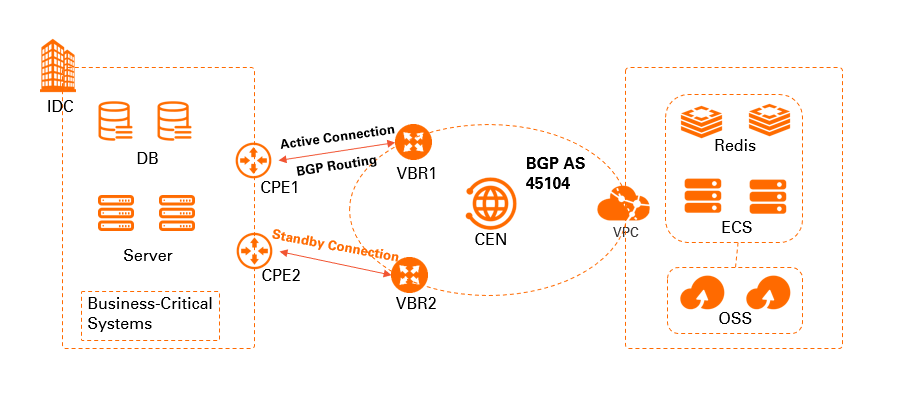
Prerequisites
Before you begin:
You have an Alibaba Cloud account. If you do not have one, sign up for an account. For more information, see Sign up for an account.
You have created a VPC in the China (Shanghai) region and deployed workloads in the VPC by using cloud resources such as Elastic Compute Service (ECS). For more information, see Create a VPC with an IPv4 CIDR block.
NoteBefore you create a VPC connection on an Enterprise Edition transit router, ensure the VPC has at least one vSwitch in a supported availability zone with at least one idle IP address. In this topic, the Enterprise Edition transit router is in the China (Shanghai) region, supporting Shanghai Zone F and Shanghai Zone G.
You understand the security group rules of the ECS instances in the VPC. Make sure that the rules allow the ECS instances to communicate with the data center. For more information, see View security group rules and Add a security group rule.
You have created a CEN instance. Create a CEN instance.
You have created an Enterprise Edition transit router in the region where the VPC resides. For more information, see Create a transit router.
You have created two Express Connect circuits (either dedicated or shared).
The following table describes the CIDR blocks used in this example. You can plan your own CIDR blocks. Make sure that your CIDR blocks do not overlap.
Component
CIDR block
Address
Data center
10.1.1.0/24
Client address: 10.1.1.1
VPC
192.168.20.0/24
Server address: 192.168.20.161
VBR1
VLAN: 110
Alibaba Cloud-side IPv4 peer IP: 172.16.1.2/30
Customer-side IPv4 peer IP: 172.16.1.1/30
Not applicable
VBR2
VLAN: 120
Alibaba Cloud-side IPv4 peer IP: 172.16.2.2/30
Customer-side IPv4 peer IP: 172.16.2.1/30
Not applicable
Step 1: Create VBRs
Create a virtual border router (VBR) for each Express Connect circuit to bridge traffic between your VPC and data center.
Log on to the Express Connect console.
In the top menu bar, select the target region, and then in the left-side navigation pane, click Virtual Border Routers (VBRs).
In the Create VBR panel, configure the following parameters and click OK.
Parameter
Description
Account
The account used to create the VBR.
This example uses Current Account.
Name
The name of the VBR.
This example uses VBR1.
Physical Connection Interfaces
Select the interface of the first Express Connect circuit.
VLAN ID
The VLAN ID of the VBR.
This example uses 110.
VBR Bandwidth
The bandwidth of the VBR.
This example uses 200Mb.
Alibaba Cloud Side IPv4 Address
The gateway IPv4 address for traffic from the VPC to the data center.
This example uses 172.16.1.2.
Data Center Side IPv4 Address
The gateway IPv4 address for traffic from the data center to the VPC.
This example uses 172.16.1.1.
IPv4 Subnet Mask
The subnet mask for the IPv4 addresses on the Alibaba Cloud side and the data center side.
This example uses 255.255.255.252.
Repeat the steps above to create a VBR instance for the second Express Connect circuit.
Use the following parameter settings:
Parameter
Description
Account
The account used to create the VBR.
This example uses Current Account.
Name
The name of the VBR.
This example uses VBR2.
Physical Connection Interfaces
Select the interface of the second Express Connect circuit.
VLAN ID
The VLAN ID of the VBR.
This example uses 120.
VBR Bandwidth
The bandwidth of the VBR.
This example uses 200Mb.
Alibaba Cloud Side IPv4 Address
The gateway IPv4 address for traffic from the VPC to the data center.
This example uses 172.16.2.2.
Data Center Side IPv4 Address
The gateway IPv4 address for traffic from the data center to the VPC.
This example uses 172.16.2.1.
IPv4 Subnet Mask
The subnet mask for the IPv4 addresses on the Alibaba Cloud side and the data center side.
This example uses 255.255.255.252.
Step 2: Connect VPC and VBR instances
Create a VPC attachment and VBR attachments on the transit router in the China (Shanghai) region to connect your data center to the VPC.
Log on to the CEN console.
On the CEN Instance page, click the ID of the CEN instance that you want to manage.
On the tab, find the transit router in the destination region and click Create Connection in the Actions column.
On the Connection with Peer Network Instance page, configure the following parameters to create a VPC connection, and then click OK.
NoteWhen you perform this operation for the first time, the system automatically creates a service-linked role named AliyunServiceRoleForCEN. This role allows the transit router to create an ENI in a vSwitch of the VPC. For more information, see AliyunServiceRoleForCEN.
Parameter
Description
Instance Type
The type of network instance.
In this example, VPC is selected.
Region
The region in which the VPC is deployed.
In this example, China (Shanghai) is selected.
TR
The system automatically displays the transit router in the selected region.
Account
The Alibaba Cloud account to which the VPC belongs.
In this example, Your Account is selected.
Billing Method
The billing method of the transit router is Pay-As-You-Go by default.
For more information, see Billing overview.
Network Instance
The ID of the VPC.
In this example, the VPC that you created is selected.
vSwitch
Select at least two vSwitches in a zone supported by the transit router.
Advanced Settings
The system selects three advanced features for you by default, namely Associate with Default Route Table of Transit Router, Propagate System Routes to Default Route Table of Transit Router, and Auto-add transit router routes to all VPC route tables.
In this example, the default settings are used.
On the Connection with Peer Network Instance page, click Create More Connections.
On the Connection with Peer Network Instance page, configure the following parameters to create an attachment for VBR1, and then click OK.
Parameter
Description
Instance Type
For this example, select Virtual Border Router (VBR).
Region
Select the region where the network instance is deployed.
For this example, select China (Shanghai).
Transit Router
The system automatically displays the transit router instance in the current region.
Account
Select the type of account that owns the network instance.
Use the default value, Your Account.
Connection Name
Enter a name for the VBR attachment.
For this example, enter VBR-test.
Networks
Select the ID of the VBR instance to attach.
For this example, select the VBR1 instance.
Advanced Settings
By default, the following advanced features are enabled: Associate with Default Route Table of Transit Router, Propagate System Routes to Default Route Table of Transit Router, and Auto-add transit router routes to all VPC route tables.
Keep the default settings.
Repeat Step 5 and Step 6 to create an attachment for VBR2.
After you create the attachments, view the VPC and VBR attachments on the Intra-Region Connections tab. View network instance connections.
Step 3: Configure routes
Configure BGP between your data center and the VBRs. Set the AS-Path length on your data center devices to control route selection priority.
Establish BGP peerings between the data center and the VBRs and advertise routes. Configure and manage BGP.
The Alibaba Cloud BGP Autonomous System Number (ASN) is 45104. Both 2-byte and 4-byte ASNs from your data center are supported.
On your data center devices, configure the BGP route (10.1.1.0/24) to advertise to Alibaba Cloud. Use the AS-Path attribute to establish primary/standby routing for traffic from Alibaba Cloud to your data center.
The circuit connected to CPE1 is the primary link; CPE2 is the standby. BGP selects the shortest AS-Path, so you control priority by adjusting AS-Path length when advertising routes. The following table shows the BGP configurations on the two CPEs. Consult your device vendor for specific commands.
Parameter | CPE1 | CPE2 |
VLAN Tag | 110 | 120 |
Network | 10.1.1.0/24 | 10.1.1.0/24 |
BGP ASN | 6***3 | 6***4 |
Interface IP | 172.16.1.1/24 | 172.16.2.1/24 |
AS-Path | B, A | C, B, A |
The CEN transit router automatically learns and distributes routes based on attributes such as AS-Path length.
BGP routes on the VBRs
Route entry
VBR1
VBR2
Destination CIDR block
10.1.1.0/24
10.1.1.0/24
Next hop
172.16.1.1
172.16.2.1
VBR1 and VBR2 learn these routes from their BGP peers and forward them (including AS-Path) to the transit router through their VBR attachments.
Summary of route configurations
CPE route configuration
Configuration
CPE1
CPE2
VLAN Tag
110
120
Network
10.1.1.0/24
10.1.1.0/24
BGP ASN
6***3
6***4
Interface IP
172.16.1.1/24
172.16.2.1/24
AS-Path
B, A
C, B, A
VBR route entries
Configuration
VBR1
VBR2
Destination CIDR block
10.1.1.0/24
10.1.1.0/24
Next hop
172.16.1.1
172.16.2.1
Data center route entries
Destination CIDR block
192.168.20.0/24
Next hop
To create a symmetric traffic path for inbound and outbound traffic, set a higher weight for the route learned from the VBR1 peer. This ensures that traffic to the cloud preferentially uses CPE1:
172.16.1.2 (High weight)
172.16.2.2 (Low weight)
Transit router route entries
Destination CIDR block
10.1.1.0/24
Next hop
VBR1
BGP routes learned by the VBRs are advertised to the transit router, which synchronizes them internally based on AS-Path length.
Both VBRs learn routes to 10.1.1.0/24 with different AS-Path lengths: VBR1 has the shorter path (primary) and VBR2 has the longer one (standby). The transit router advertises the preferred route to attached network instances, so the VPC route table directs all 10.1.1.0/24 traffic to VBR1.
The data center's BGP table shows routes learned from the transit router, with next hops pointing to the VBR interface IPs.
To create a primary/standby path from the data center to VPC CIDR block 192.168.20.0/24, set different BGP weights on your data center devices for the routes learned from VBR1 and VBR2 peers.
Step 4: Configure health checks
Configure health checks for the active/standby Express Connect circuits. If a specified number of consecutive probe packets are lost, CEN automatically switches traffic to the standby circuit.
Log on to the .CEN console
In the left-side navigation pane, click VBR Health Check.
On the VBR Health Check page, select the region of the VBR instance, and then click Add Health Check.
In this example, the VBR1 instance is deployed in the China (Shanghai) region.
In the Add Health Check dialog box, configure the following parameters and click OK.
Parameter
Description
CEN Instance
The CEN instance to which the VBR is attached.
VBR
The VBR that you want to monitor.
In this example, VBR1 is selected.
Source IP
The source IP address. You can select one of the following methods to specify the source IP address:
Automatic IP Address (recommended): The system automatically assigns an IP address within the 100.96.0.0/16 CIDR block to you.
NoteIf you select this option and an ACL policy is configured on the peer , you must modify the ACL policy to allow this CIDR block. Otherwise, the health check fails.
Custom IP Address: The source IP address can be any unused IP address within the 10.0.0.0/8, 192.168.0.0/16, or 172.16.0.0/12 CIDR block. However, it cannot conflict with the addresses that need to communicate within the Cloud Enterprise Network, nor can it conflict with the IPv4 interconnection IP on the Alibaba Cloud side or IPv4 interconnection IP on the customer side address of the Virtual Border Router instance.
Destination IP
The IP address of the VBR on the user side.
Send Packet Every (Seconds)
The interval at which probe packets are sent for the health check. Unit: seconds.
Default value: 2. Valid values: 2 to 3.
Packets Detected
The number of probe packets that are sent for health checks. Unit: packet.
Default value: 8. Valid values: 3 to 8.
Route switching
Specifies whether to allow the health check feature to switch to the redundant route.
The system selects Yes by default, which enables the route switching feature of the health check. When the health check detects a physical connection failure, if a redundant route exists in the Cloud Enterprise Network (CEN) instance, the health check immediately triggers route switching to use an available link.
If you clear Yes, the route switching feature of the health check is not enabled, and the health check only performs the link probing function. If the health check detects a physical connection failure, route switching is not triggered.
WarningBefore you turn off Change Route, make sure that the system can switch to a redundant route by using other mechanisms. Otherwise, network connections are interrupted if the Express Connect circuit is down.
NoteA health check sends probe packets at the specified interval. A health check fails if the specified number of consecutive probe packets are lost.
Repeat Step 3 to Step 4 to configure a health check for VBR2.
Step 5: Enable BFD on the VBR
Configure BFD on the VBR for fast route convergence.
Log on to the Express Connect console.
In the top menu bar, select the target region, and then in the left-side navigation pane, click Virtual Border Routers (VBRs).
On the VBR page, find the target VBR and click Edit in the Actions column.
In the Edit VBR panel, set the BFD parameters and click OK.
This table lists only the BFD-related parameters. Leave the other parameters unchanged.
Parameter
Description
Submission Interval
The interval (ms) at which BFD packets are sent.
In this example, the default value 1000 ms is used.
Reception Interval
The interval (ms) at which BFD packets are received.
In this example, the default value 1000 ms is used.
Detection Time Multiplier
The maximum number of BFD packets that can be lost before BFD declares the connection down.
The default value is 3.
Return to the VBR page and click the ID of the target VBR instance.
On the VBR instance details page, click the BGP Peers tab.
Find the target BGP peer and click Edit in the Actions column.
In the Modify BGP Peer panel, select the Enable BFD check box, configure the BFD Hop Count, and then click OK.
NoteBFD supports custom single-hop or multi-hop sessions. Set the hop count according to your physical link.
Step 6: Test connectivity
Test connectivity of the active/standby Express Connect circuits.
Before you perform the following steps, familiarize yourself with the security group rules applied to the ECS instances in your VPC and make sure that the security group rules allow the data center to access the ECS instances in the VPC. For more information, see View security group rules.
- Open the Command Prompt window of your computer at the on-premises data center.
- Run the
pingcommand to connect to an ECS instance that belongs to the 192.168.0.0/24 CIDR block in the VPC. If the ping request is successful, the connection between the on-premises data center and Alibaba Cloud is established. - Disconnect a leased line (for example, from VBR1 to CPE1) and run the
tracertcommand. You can see that the CEN instance switches routes and that all traffic from Alibaba Cloud to the on-premises data center is forwarded over VBR2.