This topic describes how to use E-MapReduce (EMR) Hive nodes in DataWorks to process data in the ods_user_info_d_emr and the ods_raw_log_d_emr tables, which are stored in an Object Storage Service (OSS) bucket after synchronization, to obtain the desired user profile data. The ods_user_info_d_emr table stores basic user information and the ods_raw_log_d_emr table stores website access logs.
Prerequisites
The required data is synchronized. For more information, see Synchronize data.
Step 1: Design a workflow
For information about the dependencies between nodes in a workflow, see Synchronize data.
In the Scheduled Workflow pane of the DataStudio page, double-click the workflow. On the configuration tab of the workflow, click Create Node and drag EMR Hive to the canvas. In the Create Node dialog box, configure the Name parameter and click Confirm.
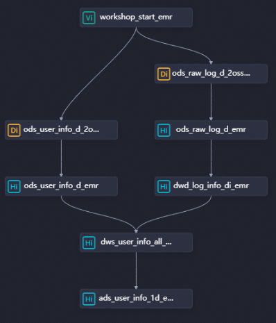
You must create three EMR Hive nodes named dwd_log_info_di_emr, dws_user_info_all_di_emr, and ads_user_info_1d_emr. Then, configure the node dependencies as shown in the following figure.
dwd_log_info_di_emr: used to cleanse the raw OSS log data.
dws_user_info_all_di_emr: used to aggregate the cleansed OSS log data and the basic user information.
ads_user_info_1d_emr: used to generate user profile data.
Step 2: Create a function
You can use a function to convert the synchronized log data from the original format into the desired format. In the example in this topic, a function code package that is used to translate IP addresses into regions is provided. After you download the function code package to your on-premises machine and register the code package as a function in DataWorks, you can call the function.
Upload resources
Download the ip2region-emr.jar package.
On the DataStudio page, find the workflow named WorkShop, right-click EMR, and then choose . In the Create Resource dialog box, configure the parameters and click Create.
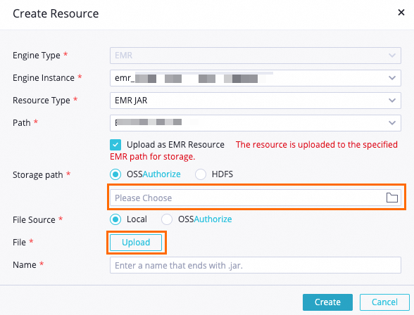
Key parameters:
Storage path: Select the OSS bucket that you specified for the EMR cluster you created during environment preparation.
File: Select the downloaded ip2region-emr.jar package.
Configure other parameters based on your business requirements or use the default values.
Click the
 icon in the toolbar to commit the resource to the EMR project in the development environment.
Register a function
On the DataStudio page, find the workflow named WorkShop, right-click EMR, and then select Create Function.
In the Create Function dialog box, set the Name parameter to getregion and click Create. On the tab that appears, configure the parameters.
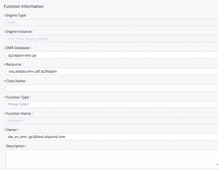
Key parameters:
Resource: Set the value to ip2region-emr.jar.
Class Name: Set the value to org.alidata.emr.udf.Ip2Region.
Configure other parameters based on your business requirements or use the default values.
Click the
icon in the toolbar to commit the function to the EMR project in the development environment.
Step 3: Configure the EMR Hive nodes
Create the dwd_log_info_di_emr node
1. Edit node code
Double-click the dwd_log_info_di_emr node to go to the node configuration tab. On the configuration tab, enter the following statements:
If multiple EMR compute engines are associated with DataStudio in your workspace, you must select an EMR compute engine based on your business requirements. If only one EMR compute engine is associated with DataStudio in your workspace, you do not need to select a compute engine.
-- Create a table at the ODS layer.
CREATE TABLE IF NOT EXISTS dwd_log_info_di_emr (
ip STRING COMMENT 'The IP address',
uid STRING COMMENT 'The user ID',
`time` STRING COMMENT 'The time in the yyyymmddhh:mi:ss format',
status STRING COMMENT 'The status code that is returned by the server',
bytes STRING COMMENT 'The number of bytes that are returned to the client',
region STRING COMMENT 'The region, which is obtained based on the IP address',
method STRING COMMENT 'The HTTP request type',
url STRING COMMENT 'url',
protocol STRING COMMENT 'The version number of HTTP',
referer STRING COMMENT 'The source URL',
device STRING COMMENT 'The terminal type',
identity STRING COMMENT 'The access type, which can be crawler, feed, user, or unknown'
)
PARTITIONED BY (
dt STRING
);
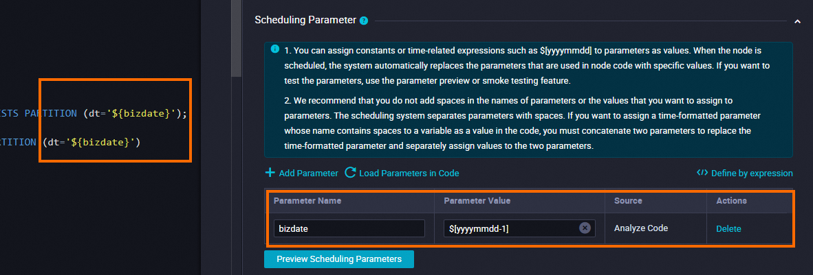
ALTER TABLE dwd_log_info_di_emr ADD IF NOT EXISTS PARTITION (dt='${bizdate}');
set hive.vectorized.execution.enabled = false;
INSERT OVERWRITE TABLE dwd_log_info_di_emr PARTITION (dt='${bizdate}')
SELECT ip
, uid
, tm
, status
, bytes
, getregion(ip) AS region -- Obtain the region by using a user defined function (UDF) based on the IP address.
, regexp_substr(request, '(^[^ ]+ )') AS method -- Use a regular expression to extract three fields from the request.
, regexp_extract(request, '^[^ ]+ (.*) [^ ]+$') AS url
, regexp_extract(request, '.* ([^ ]+$)') AS protocol
, regexp_extract(referer, '^[^/]+://([^/]+){1}') AS referer -- Use a regular expression to cleanse the HTTP referrer to obtain a more accurate URL.
, CASE
WHEN lower (agent) RLIKE 'android' THEN 'android' -- Obtain the terminal and access types from the value of the agent parameter.
WHEN lower(agent) RLIKE 'iphone' THEN 'iphone'
WHEN lower(agent) RLIKE 'ipad' THEN 'ipad'
WHEN lower(agent) RLIKE 'macintosh' THEN 'macintosh'
WHEN lower(agent) RLIKE 'windows phone' THEN 'windows_phone'
WHEN lower(agent) RLIKE 'windows' THEN 'windows_pc'
ELSE 'unknown'
END AS device
, CASE
WHEN lower(agent) RLIKE '(bot|spider|crawler|slurp)' THEN 'crawler'
WHEN lower(agent) RLIKE 'feed'
OR regexp_extract(request, '^[^ ]+ (.*) [^ ]+$') RLIKE 'feed' THEN 'feed'
WHEN lower(agent) NOT RLIKE '(bot|spider|crawler|feed|slurp)'
AND agent RLIKE '^[Mozilla|Opera]'
AND regexp_extract(request, '^[^ ]+ (.*) [^ ]+$') NOT RLIKE 'feed' THEN 'user'
ELSE 'unknown'
END AS identity
FROM (
SELECT SPLIT(col, '##@@')[0] AS ip
, SPLIT(col, '##@@')[1] AS uid
, SPLIT(col, '##@@')[2] AS tm
, SPLIT(col, '##@@')[3] AS request
, SPLIT(col, '##@@')[4] AS status
, SPLIT(col, '##@@')[5] AS bytes
, SPLIT(col, '##@@')[6] AS referer
, SPLIT(col, '##@@')[7] AS agent
FROM ods_raw_log_d_emr
WHERE dt = '${bizdate}'
) a;2. Configure scheduling properties
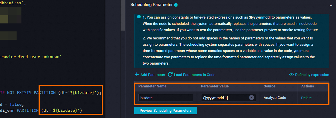
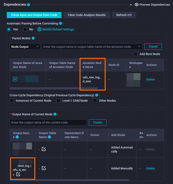
If you configure scheduling properties for the dwd_log_info_di_emr node as shown in the following table, after the ods_raw_log_d_emr node, which is the ancestor node of the dwd_log_info_di_emr node, synchronizes data from the OSS object user_log.txt to the EMR table ods_raw_log_d_emr at 00:30 every day in the scheduling scenario, the dwd_log_info_di_emr node is triggered to process the data in the ods_raw_log_d_emr table and write the processed data to the data timestamp-based partition in the dwd_log_info_di_emr table.
Section | Description | Screenshot |
Scheduling Parameter | Click Add Parameter in the Scheduling Parameter section. In the row that appears in the table, you can specify a scheduling parameter and the value of the scheduling parameter.
|
|
Schedule | Set the Rerun parameter to Allow Regardless of Running Status. |
|
Dependencies | Make sure that the generated table is used as the output table of the current node. The output table is named in the |
|
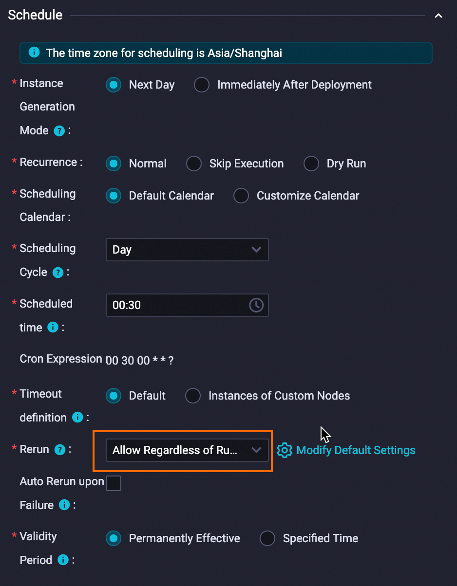
In the Schedule section, set the Scheduling Cycle parameter to Day. You do not need to separately configure the Scheduled time parameter for the current node. The time when the current node is scheduled to run every day is determined by the scheduling time of the workshop_start_emr zero load node of the workflow. The current node is scheduled to run after 00:30 every day.
3. Save the configurations
In this example, you can configure other required configuration items based on your business requirements. After the configuration is complete, click the ![]() icon in the top toolbar on the configuration tab of the node to save the node configurations.
icon in the top toolbar on the configuration tab of the node to save the node configurations.
Create the dws_user_info_all_di_emr node
1. Edit node code
Double-click the dws_user_info_all_di_emr node to go to the node configuration tab. On the configuration tab, enter the following statements:
If multiple EMR compute engines are associated with DataStudio in your workspace, you must select an EMR compute engine based on your business requirements. If only one EMR compute engine is associated with DataStudio in your workspace, you do not need to select a compute engine.
-- Create a table at the DW layer.
CREATE TABLE IF NOT EXISTS dws_user_info_all_di_emr (
  uid STRING COMMENT 'The user ID',
  gender STRING COMMENT 'The gender',
  age_range STRING COMMENT 'The age range',
  zodiac STRING COMMENT 'The zodiac sign',
  region STRING COMMENT 'The region, which is obtained based on the IP address',
  device STRING COMMENT 'The terminal type',
  identity STRING COMMENT 'The access type, which can be crawler, feed, user, or unknown',
  method STRING COMMENT 'The HTTP request type',
  url STRING COMMENT 'url',
  referer STRING COMMENT 'The source URL',
  `time` STRING COMMENT 'The time in the yyyymmddhh:mi:ss format',
)
PARTITIONED BY (
  dt STRING
);

ALTER TABLE dws_user_info_all_di_emr ADD IF NOT EXISTS PARTITION (dt='${bizdate}');

INSERT OVERWRITE TABLE dws_user_info_all_di_emr PARTITION (dt='${bizdate}')
SELECT COALESCE(a.uid, b.uid) AS uid
  , b.gender
  , b.age_range
  , b.zodiac
  , a.region
  , a.device
  , a.identity
  , a.method
  , a.url
  , a.referer
  , a.`time`
FROM (
  SELECT *
  FROM dwd_log_info_di_emr
  WHERE dt = '${bizdate}'
) a
LEFT OUTER JOIN (
  SELECT *
  FROM ods_user_info_d_emr
  WHERE dt = '${bizdate}'
) b
ON a.uid = b.uid;
2. Configure scheduling properties
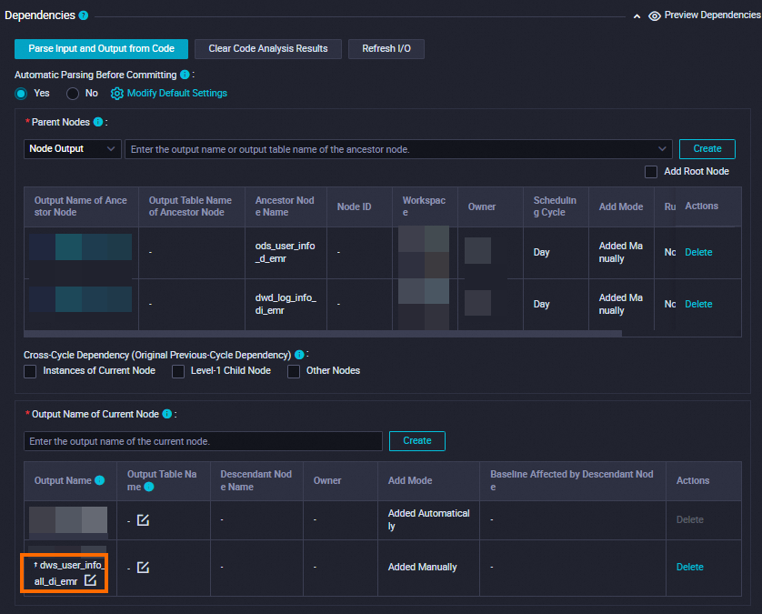
Configure scheduling properties for the dws_user_info_all_di_emr node as shown in the following table. After the ods_user_info_d_emr and dwd_log_info_di_emr nodes, the ancestor nodes of the dws_user_info_all_di_emr node, finish running at 00:30 every day in the scheduling scenario, the dws_user_info_all_di_emr node is triggered to combine and process the ods_user_info_d_emr and dwd_log_info_di_emr tables and write the processed data to the dws_user_info_all_di_emr table.
Section | Description | Screenshot |
Scheduling Parameter | Click Add Parameter in the Scheduling Parameter section. In the row that appears in the table, you can specify a scheduling parameter and the value of the scheduling parameter.
|
|
Schedule | Set the Rerun parameter to Allow Regardless of Running Status. |
|
Dependencies | Make sure that the generated table is used as the output table of the current node. The output table is named in the |
|
In the Schedule section, set the Scheduling Cycle parameter to Day. You do not need to separately configure the Scheduled time parameter for the current node. The time when the current node is scheduled to run every day is determined by the scheduling time of the workshop_start_emr zero load node of the workflow. The current node is scheduled to run after 00:30 every day.
3. Save the configurations
In this example, you can configure other required configuration items based on your business requirements. After the configuration is complete, click the ![]() icon in the top toolbar on the configuration tab of the node to save the node configurations.
icon in the top toolbar on the configuration tab of the node to save the node configurations.
Create the ads_user_info_1d_emr node
1. Edit node code
Double-click the ads_user_info_1d_emr node to go to the node configuration tab. On the configuration tab, enter the following statements:
If multiple EMR compute engines are associated with DataStudio in your workspace, you must select an EMR compute engine based on your business requirements. If only one EMR compute engine is associated with DataStudio in your workspace, you do not need to select a compute engine.
-- Create a table at the RPT layer.
CREATE TABLE IF NOT EXISTS ads_user_info_1d_emr (
  uid STRING COMMENT 'The user ID',
  region STRING COMMENT 'The region, which is obtained based on the IP address',
  device STRING COMMENT 'The terminal type',
  pv BIGINT COMMENT 'pv',
  gender STRING COMMENT 'The gender',
  age_range STRING COMMENT 'The age range',
  zodiac STRING COMMENT 'The zodiac sign'
)
PARTITIONED BY (
  dt STRING
);

ALTER TABLE ads_user_info_1d_emr ADD IF NOT EXISTS PARTITION (dt='${bizdate}');

INSERT OVERWRITE TABLE ads_user_info_1d_emr PARTITION (dt='${bizdate}')
SELECT uid
  , MAX(region)
  , MAX(device)
  , COUNT(0) AS pv
  , MAX(gender)
  , MAX(age_range)
  , MAX(zodiac)
FROM dws_user_info_all_di_emr
WHERE dt = '${bizdate}'
GROUP BY uid;
2. Configure scheduling properties
After the dws_user_info_all_di_emr node merges the ods_user_info_d_emr and dwd_log_info_di_emr tables, the ads_user_info_1d_emr node can be triggered to further process the data to generate consumable data.
Section | Description | Screenshot |
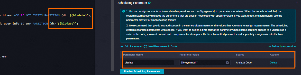
Scheduling Parameter | Click Add Parameter in the Scheduling Parameter section. In the row that appears in the table, you can specify a scheduling parameter and the value of the scheduling parameter.
|
|
Schedule | Set the Rerun parameter to Allow Regardless of Running Status. |
|
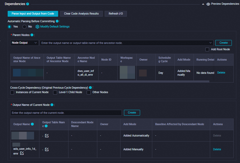
Dependencies | Make sure that the generated table is used as the output table of the current node. The output table is named in the |
|
In the Schedule section, set the Scheduling Cycle parameter to Day. You do not need to separately configure the Scheduled time parameter for the current node. The time when the current node is scheduled to run every day is determined by the scheduling time of the workshop_start_emr zero load node of the workflow. The current node is scheduled to run after 00:30 every day.
3. Save the configurations
In this example, you can configure other required configuration items based on your business requirements. After the configuration is complete, click the ![]() icon in the top toolbar on the configuration tab of the node to save the node configurations.
icon in the top toolbar on the configuration tab of the node to save the node configurations.
Step 4: Commit the workflow
After you configure the workflow, test whether the workflow can be run as expected. If the test is successful, commit the workflow and wait for the workflow to be deployed.
On the configuration tab of the workflow, click the
 icon to run the workflow.
 If the
 icon appears next to all nodes in the workflow, click the
  icon to commit the workflow.
 In the Commit dialog box, select the nodes that you want to commit, enter a description, and then select Ignore I/O Inconsistency Alerts. Then, click Confirm.
After the workflow is committed, you can deploy the nodes in the workflow.
In the upper-right corner of the configuration tab of the workflow, click Deploy. The Create Deploy Task page appears.
Select the nodes that you want to deploy and click Deploy. In the Create Deploy Task dialog box, click Deploy.
Step 5: Run the nodes in the production environment
After you deploy the nodes on a day, the instances generated for the nodes can be scheduled to run on the next day. You can use the data backfill feature to backfill data for nodes in a workflow that is deployed, which allows you to check whether the nodes can be run in the production environment. For more information, see Backfill data and view data backfill instances (new version).
After you deploy the nodes, click Operation Center in the upper-right corner.
You can also click Operation Center in the top toolbar on the configuration tab of the workflow to go to the Operation Center page.
In the left-side navigation pane of the Operation Center page, choose . On the Auto Triggered Nodes page, click the name of the workshop_start_emr zero load node.
In the directed acyclic graph (DAG) of the node on the right, right-click the workshop_start_emr node and choose .
In the Backfill Data panel, select the nodes for which you want to backfill data, configure the Data Timestamp parameter, and then click Submit and Redirect.
On the data backfill page, click Refresh until all SQL nodes are successfully run.
What to do next
To ensure that the table data generated by nodes in a periodic scheduling scenario meets your business requirements, you can configure monitoring rules to monitor the quality of the table data generated by the nodes. For more information, see Monitor data quality.