Enterprise Edition transit routers provide flexible routing management. You can use a transit router to build a service chain. This chain directs traffic to a security server for filtering. This ensures that only filtered traffic is communicated, which improves your network security.
Scenario
This topic uses an intra-region network as an example to show how to use an Enterprise Edition transit router to enable secure network communication. A company has deployed three virtual private clouds (VPCs) in the China (Hangzhou) region. VPC1 contains security services. The three VPCs cannot communicate with each other. For business growth and network security, the company wants to enable communication between VPC2 and VPC3. However, traffic between VPC2 and VPC3 must be filtered by the security services in VPC1.
The company can connect VPC2 and VPC3 to an Enterprise Edition transit router. By creating custom routes in the transit router, the company can fulfill the requirement for secure communication between VPC2 and VPC3.

Prerequisites
Before you begin, make sure that the region where the virtual private cloud (VPC) that contains the security service is located supports Enterprise Edition transit routers. This is required to enable secure network communication. For more information, see Supported regions and zones for Enterprise Edition transit routers.
You have created three VPCs in the China (Hangzhou) region. An Elastic Compute Service (ECS) instance is deployed in each VPC. For more information, see Create a VPC with an IPv4 CIDR block.
Make sure that each VPC has a sufficient number of vSwitches in the zones supported by the Enterprise Edition transit router, and that each vSwitch has at least one idle IP address.
If the Enterprise Edition transit router is deployed in a region that supports only one zone, for example, China (Nanjing - Local Region), the VPC must have at least one vSwitch in the zone.
If the Enterprise Edition transit router is deployed in a region that supports multiple zones, for example, China (Shanghai), the VPC must have at least two vSwitches in the zones. The vSwitches must be in different zones.
For example, if you create a VPC in the China (Hangzhou) region, the VPC must have at least one vSwitch instance in Zone J and one in Zone K. Each vSwitch instance must have at least one idle IP address.
NoteThe Enterprise Edition transit router creates an elastic network interface (ENI) on a vSwitch in a zone. The ENI serves as an entry point for traffic from the VPC to the transit router. Each ENI consumes one IP address.
In this example, VPC1 has three vSwitch instances. vSwitch1 is used to deploy the security service. vSwitch2 and vSwitch3 are used to connect to the Enterprise Edition transit router. The following table describes the network planning for the three VPCs. When you plan your network, make sure that the CIDR blocks of the networks that need to communicate do not overlap. For the three ECS instances, select the Alibaba Cloud Linux image.
VPC
vSwitch
vSwitch zone
CIDR block
ECS address
VPC1
CIDR block: 10.0.0.0/16
vSwitch1
Zone I
10.0.0.0/24
ECS1: 10.0.0.1
vSwitch2
Zone J
10.0.1.0/24
vSwitch3
Zone K
10.0.2.0/24
VPC2
CIDR block: 10.1.0.0/16
vSwitch4
Zone I
10.1.0.0/24
ECS2: 10.1.0.1
vSwitch5
Zone J
10.1.1.0/24
vSwitch6
Zone K
10.1.2.0/24
VPC3
CIDR block: 10.2.0.0/16
vSwitch7
Zone I
10.2.0.0/24
ECS3: 10.2.0.1
vSwitch8
Zone J
10.2.1.0/24
vSwitch 9
Zone K
10.2.2.0/24
You must understand the security group rules that apply to the ECS instances in VPC1, VPC2, and VPC3. Make sure that the security group rules allow inbound traffic over the ICMP protocol. For more information, see Query security group rules and Add a security group rule.
Get started
This topic describes how to perform the configuration in the console and using Terraform. You can select a method as needed.
Console
Step 1: Create a CEN instance
A CEN instance is the basic resource for creating and managing an integrated network. Before you can connect network instances using an Enterprise Edition transit router, you must create a CEN instance.
Log on to the CEN console.
On the Instances page, click Create CEN Instance.
In the Create CEN Instance dialog box, configure the following parameters and click OK.
Name: Enter a name for the CEN instance.
Description: Enter a description for the CEN instance.
Resource Group and Tag: Select a resource group for the CEN instance.
In this example, no resource group is selected. After the CEN instance is created, it is added to the default resource group.
Add tags to the CEN instance. In this example, no tag is added to the CEN instance.
Step 2: Create a transit router instance
Before you can connect network instances using an Enterprise Edition transit router, you must create a transit router in the region where the network instances are deployed.
Log on to the CEN console.
On the Instances page, select the CEN instance that you created in Step 1 and click its instance ID.
On the tab, click Create Transit Router.
In the Create Transit Router dialog box, configure the transit router and click OK.
Parameter
Description
Setting
Region
Select the region where the transit router is located.
In this example, China (Hangzhou) is selected.
Edition
The edition of the transit router.
The system automatically determines and displays the edition of the transit router in the current region.
Enable Multicast
Specifies whether to enable the multicast feature for the transit router.
In this example, the default value is used, and the multicast feature is not enabled.
Name
Enter a name for the transit router.
Enter a custom name for the transit router.
Description
Enter a description for the transit router.
Enter a custom description for the transit router.
Tag
Add a tag to the Enterprise Edition transit router.
This topic is empty.
Transit Router CIDR
Enter a CIDR block for the transit router.
For more information, see Transit router CIDR block.
In this example, a CIDR block is not entered for the transit router.
Step 3: Connect the VPC instances
Connect the network instances for which you want to enable communication to the Enterprise Edition transit router.
Log on to the CEN console.
On the Instances page, click the ID of the CEN instance that you want to manage.
Go to the tab, find the transit router that you want to manage, and then click Create Connection in the Actions column.
On the Connection with Peer Network Instance page, set the following parameters and click OK.
The following table describes the parameters and their values for VPC1, VPC2, and VPC3. Use the information in the table to connect VPC1, VPC2, and VPC3 to the Enterprise Edition transit router.
Parameter
Description
VPC1
VPC2
VPC3
Network Type
Select the type of network instance to connect.
VPC
VPC
VPC
Region
Select the region where the network instance is deployed.
China (Hangzhou)
China (Hangzhou)
China (Hangzhou)
Transit Router
The system automatically displays the transit router instances that are created in the region.
Resource Owner ID
Select the type of account to which the network instance belongs.
Same Account
Same Account
Same Account
Billing Method
The default value is Pay-As-You-Go.
Attachment Name
Enter a name for the network instance connection.
attach1attach2attach3Tag
Add a tag to the network instance connection.
This topic contains no content.
This topic is intentionally left blank.
This topic contains no content.
Networks
Select the network instance to connect.
Select VPC1
Select VPC2
Select VPC3
VSwitch
Select a vSwitch in a zone that supports the transit router.
If you have vSwitches in multiple zones that support the transit router, you can select multiple zones and select one vSwitch in each zone to implement zone-level disaster recovery.
China (Hangzhou) Zone J: Select vSwitch2
China (Hangzhou) Zone K: Select vSwitch3
China (Hangzhou) Zone I: Select vSwitch4
China (Hangzhou) Zone J: Select vSwitch5
China (Hangzhou) Zone I: Select vSwitch7
China (Hangzhou) Zone J: Select vSwitch8
Advanced Settings
Do not enable the following three advanced features for VPC1, VPC2, or VPC3.
Associate with Default Route Table of Transit Router
Propagate System Routes to Default Route Table of Transit Router
Automatically Creates Route That Points to Transit Router and Adds to All Route Tables of Current VPC
NoteIf you enable the advanced features, VPC1, VPC2, and VPC3 automatically learn routes from each other and can communicate. However, this does not meet the goal of secure traffic communication. Therefore, this example does not enable the advanced features for the VPCs. In the following steps, you will manually create route tables and add route entries to customize connectivity and enable secure traffic communication.
Step 4: Add route entries to the VPCs
Add route entries to VPC1, VPC2, and VPC3 to direct traffic from the VPCs to the Enterprise Edition transit router. In the transit router, you can then manage the traffic to enable secure communication.
Log on to the VPC console.
In the top navigation bar, select the region where the route table is located.
Add a custom route entry to VPC2 and VPC3.
In the system route tables of VPC2 and VPC3, add a route entry whose destination CIDR block is 0.0.0.0/0 and whose next hop is the transit router. This forwards all traffic from VPC2 and VPC3 to the Enterprise Edition transit router.
In the navigation pane on the left, click Route Tables.
On the Route Tables page, find the destination route table and click its ID.
In this example, find the system route table of VPC2.
On the Route Entry List tab, click the Custom Route tab, and then click Add Route Entry.
In the Add Route Entry panel, set the following parameters and click OK.
Name: Enter a name for the custom route entry.
Destination CIDR Block: Enter 0.0.0.0/0 for this example.
Next Hop Type: Select Transit Router for this example.
Transit Router: Select the transit router associated with VPC2 for this example.
Repeat the preceding steps to add the same route entry to the system route table of VPC3. Set the following parameters.
Destination CIDR Block: Enter 0.0.0.0/0 for this example.
Next Hop Type: Select Transit Router for this example.
Transit Router: Select the transit router associated with VPC3 for this example.
Create three custom route tables for VPC1 and name them routetable1, routetable2, and routetable3. For more information, see Create a custom route table.
Associate the vSwitches with the custom route tables. For more information, see Associate a vSwitch with a route table.
In this example, associate vSwitch1 in VPC1 with routetable1, vSwitch2 with routetable2, and vSwitch3 with routetable3.
Add route entries to the custom route tables of VPC1.
On the Route Tables page, click the custom route table routetable1 that is associated with vSwitch1.
On the Route Entry List tab, click the Custom Route tab, and then click Add Route Entry.
In the Add Route Entry panel, set the following parameters and click OK.
Destination CIDR Block: Enter
0.0.0.0/0.Next Hop Type: Select Transit Router.
Transit Router: Select
attach1.
Repeat the preceding steps to add a route entry to the custom route table routetable2 of vSwitch2:
Destination CIDR Block: Enter
0.0.0.0/0.Next Hop Type: Select ECS Instance.
ECS Instance: Select ECS1 (the security instance).
Continue to repeat the preceding steps to add a route entry to the custom route table routetable3 of vSwitch3:
Destination CIDR Block: Enter
0.0.0.0/0.Next Hop Type: Select ECS Instance.
ECS Instance: Select ECS1 (the security instance).
After the route entries are created, the new route entries in each VPC are shown in the following table:
Network instance
Route table name
Associated vSwitch
Route entry
Next hop
VPC1
routetable1
vSwitch1
0.0.0.0/0
attach1(Transit Router)routetable2
vSwitch2
0.0.0.0/0
ECS1
routetable3
vSwitch3
0.0.0.0/0
ECS1
VPC2
System route table
vSwitch1
vSwitch2
vSwitch3
0.0.0.0/0
attach2(Transit Router)VPC3
System route table
vSwitch1
vSwitch2
vSwitch3
0.0.0.0/0
attach3(Transit Router)
Step 5: Configure routes in the transit router
After traffic from the VPCs enters the Enterprise Edition transit router, you can customize connectivity by creating route tables and adding route entries. This guides traffic from VPC2 and VPC3 to VPC1 and then forwards the filtered traffic from VPC1 to its destination.
Log on to the CEN console.
On the Instances page, click the ID of the CEN instance.
Go to the tab and click the ID of the transit router that you want to manage.
On the Route Table tab, create two custom route tables for the Enterprise Edition transit router. Name them TR_routetable1 and TR_routetable2. For more information, see Custom route tables.
Associate
attach2andattach3with a custom route table of the Enterprise Edition transit router and configure route entries.On the Route Table tab, select the custom route table TR_routetable1, click the Route Table Association tab, and then click Create Association.
In the Add Association dialog box, select the network instance connections to associate with the custom route table and click OK.
In this example, you can associate
attach2and theVPC3connection with this custom route table.On the details page of the route table, click the Route Entry tab and click Create Route Entry.
In the Add Route Entry dialog box, set the following parameters and click OK.
Destination CIDR: Enter 0.0.0.0/0 for this example.
Blackhole Route: If you select Yes, the traffic that is destined for this route is dropped. In this example, No is selected.
Next Hop: Select
attach1for this example.
For more information, see Custom route entries for a transit router.
After you complete these steps, all traffic from VPC2 and VPC3 is forwarded to VPC1.
Associate VPC1 with a custom route table and configure route entries.
On the Route Table tab, select the custom route table TR_routetable2, click the Route Table Association tab, and then click Create Association.
In the Add Association dialog box, select the network instance connection to associate with the custom route table and click OK.
In this example, associate
attach1with this custom route table.On the details page of the route table, click the Route Propagation tab and click Enable Route Propagation.
In the Enable Route Propagation dialog box, select the network instance connections from which the route table learns routes, and then click OK.
In this example, for Attachment, select
attach2andattach3. After the association, the route table learns the routes of VPC2 and VPC3. VPC1 can then communicate with VPC2 and VPC3 by looking up this route table.
After the route entries are created, the route entries of the Enterprise Edition transit router are shown in the following table:
Route table name
Destination CIDR block
Next hop
TR_routetable1
0.0.0.0/0
attach1TR_routetable2
10.1.0.0/16
attach210.2.0.0/16
attach3
Step 6: Test and verify
After you complete the preceding steps, VPC1, VPC2, and VPC3 can securely communicate with each other along the expected path. The following steps describe how to test the traffic path between the VPCs.
Log on to ECS1 and run the following command to enable IP forwarding. For more information about how to log on to an ECS instance, see Select a method for remote connection.
NoteIf IP forwarding is not enabled, VPC2 and VPC1 can communicate with each other, and VPC3 and VPC1 can communicate with each other. However, VPC2 and VPC3 cannot communicate with each other.
echo 1 > /proc/sys/net/ipv4/ip_forward # Enable IP forwarding. This command takes effect temporarily and the setting is lost after a restart.Log on to ECS2 and install mtr. mtr is a network diagnostic tool that combines the features of ping and traceroute. It analyzes network path latency and packet loss in real time. In this topic, mtr is used to identify the traffic path.
yum install -y mtrOn ECS2, run the mtr command to test the traffic path from ECS2 to ECS3:
mtr 10.2.0.1 -i 5Parameter description:
-i 5specifies that a ping request is sent every 5 seconds.
The command output shows that packets sent from ECS2 to ECS3 are forwarded through 10.0.0.1 (ECS1). This indicates that traffic between VPC2 and VPC3 is routed through ECS1 (the security ECS instance).
Terraform
You can use Terraform to build the environment for the scenario in this topic. For information about how to install and configure Terraform, see Install Terraform.
The following steps use a Linux host that runs Terraform v1.9.8 as an example. Before you begin, make sure that you have completed the Authentication.
Some resources in this tutorial incur fees. You should release them if they are no longer needed to avoid further charges.
Step 1: Create resources
Create a directory for this scenario and navigate to the directory.
mkdir tf-CenSec && cd tf-CenSecCreate a
main.tffile to define the resources.touch main.tfOpen the
main.tffile. Copy the following code to the file and save it. This file contains the resources and configurations required for this scenario.variable "pname" { description = "The prefix name for the resources" type = string default = "tf-CenSec" } variable "default_region" { description = "Default region" type = string default = "cn-hangzhou" } variable "az" { description = "List of availability zones to use" type = list(string) default = ["cn-hangzhou-i", "cn-hangzhou-j", "cn-hangzhou-k"] } variable "vpc_count" { description = "Number of VPCs to create" type = number default = 3 } provider "alicloud" { region = var.default_region } # VPC resource "alicloud_vpc" "main" { count = var.vpc_count vpc_name = "${var.pname}-vpc${count.index + 1}" cidr_block = "10.${count.index}.0.0/16" } # vSwitch resource "alicloud_vswitch" "main" { count = var.vpc_count * length(var.az) vpc_id = alicloud_vpc.main[floor(count.index / length(var.az))].id cidr_block = "10.${floor(count.index / length(var.az))}.${count.index % length(var.az)}.0/24" zone_id = var.az[count.index % length(var.az)] vswitch_name = "${var.pname}-vsw${count.index + 1}" } # ECS resource "alicloud_instance" "main" { count = var.vpc_count instance_name = "${var.pname}-ecs${count.index + 1}" instance_type = "ecs.e-c1m1.large" security_groups = [alicloud_security_group.main[count.index].id] vswitch_id = alicloud_vswitch.main[count.index * length(var.az)].id image_id = "aliyun_3_x64_20G_qboot_alibase_20230727.vhd" system_disk_category = "cloud_essd" private_ip = "10.${count.index}.0.1" instance_charge_type = "PostPaid" user_data = base64encode(<<-EOT #!/bin/bash ${count.index == 0 ? "echo 1 > /proc/sys/net/ipv4/ip_forward" : ""} yum install -y traceroute yum install -y mtr EOT ) # Enable IP forwarding for ECS1. } # Security group resource "alicloud_security_group" "main" { count = var.vpc_count name = "${var.pname}-${count.index + 1}" vpc_id = alicloud_vpc.main[count.index].id } resource "alicloud_security_group_rule" "allow_inbound_ssh" { count = var.vpc_count type = "ingress" ip_protocol = "tcp" nic_type = "intranet" policy = "accept" port_range = "22/22" priority = 1 security_group_id = alicloud_security_group.main[count.index].id cidr_ip = "0.0.0.0/0" } resource "alicloud_security_group_rule" "allow_inbound_icmp" { count = var.vpc_count type = "ingress" ip_protocol = "icmp" nic_type = "intranet" policy = "accept" port_range = "-1/-1" priority = 1 security_group_id = alicloud_security_group.main[count.index].id cidr_ip = "0.0.0.0/0" } resource "alicloud_security_group_rule" "allow_all_outbound" { count = var.vpc_count type = "egress" ip_protocol = "tcp" nic_type = "intranet" policy = "accept" port_range = "1/65535" priority = 1 security_group_id = alicloud_security_group.main[count.index].id cidr_ip = "0.0.0.0/0" } # CEN resource "alicloud_cen_instance" "cen1" { cen_instance_name = var.pname } # Transit router resource "alicloud_cen_transit_router" "tr1" { transit_router_name = var.pname cen_id = alicloud_cen_instance.cen1.id } # Attach attach1 to vSwitch2 and vSwitch3 in VPC1. resource "alicloud_cen_transit_router_vpc_attachment" "attach1" { cen_id = alicloud_cen_instance.cen1.id transit_router_id = alicloud_cen_transit_router.tr1.transit_router_id vpc_id = alicloud_vpc.main[0].id zone_mappings { zone_id = var.az[1] vswitch_id = alicloud_vswitch.main[1].id # vSwitch2, vpc1-2 } zone_mappings { zone_id = var.az[2] vswitch_id = alicloud_vswitch.main[2].id # vSwitch3, vpc1-3 } transit_router_vpc_attachment_name = "attach1" } # Attach attach2 to vSwitch4 and vSwitch5 in VPC2. resource "alicloud_cen_transit_router_vpc_attachment" "attach2" { cen_id = alicloud_cen_instance.cen1.id transit_router_id = alicloud_cen_transit_router.tr1.transit_router_id vpc_id = alicloud_vpc.main[1].id zone_mappings { zone_id = var.az[0] vswitch_id = alicloud_vswitch.main[3].id # vSwitch4, vpc2-1 } zone_mappings { zone_id = var.az[1] vswitch_id = alicloud_vswitch.main[4].id # vSwitch5, vpc2-2 } transit_router_vpc_attachment_name = "attach2" } # Attach attach3 to vSwitch7 and vSwitch8 in VPC3. resource "alicloud_cen_transit_router_vpc_attachment" "attach3" { cen_id = alicloud_cen_instance.cen1.id transit_router_id = alicloud_cen_transit_router.tr1.transit_router_id vpc_id = alicloud_vpc.main[2].id zone_mappings { zone_id = var.az[0] vswitch_id = alicloud_vswitch.main[6].id # vSwitch7, vpc3-1 } zone_mappings { zone_id = var.az[1] vswitch_id = alicloud_vswitch.main[7].id # vSwitch8, vpc3-2 } transit_router_vpc_attachment_name = "attach3" } # Create three route tables for VPC1. resource "alicloud_route_table" "rt" { count = 3 vpc_id = alicloud_vpc.main[0].id route_table_name = "${var.pname}-rt${count.index}" associate_type = "VSwitch" } # Associate the three route tables with vSwitch1, vSwitch2, and vSwitch3. resource "alicloud_route_table_attachment" "rt_attach" { count = 3 vswitch_id = alicloud_vswitch.main[count.index].id route_table_id = alicloud_route_table.rt[count.index].id } # Route entry for VPC1 resource "alicloud_route_entry" "rt-entry1" { # Next hop is the transit router. route_table_id = alicloud_route_table.rt[0].id destination_cidrblock = "0.0.0.0/0" nexthop_type = "Attachment" nexthop_id = alicloud_cen_transit_router_vpc_attachment.attach1.transit_router_attachment_id } resource "alicloud_route_entry" "rt-entry2" { # Next hop is ECS1. route_table_id = alicloud_route_table.rt[1].id destination_cidrblock = "0.0.0.0/0" nexthop_type = "Instance" nexthop_id = alicloud_instance.main[0].id # ECS1 } resource "alicloud_route_entry" "rt-entry3" { # Next hop is ECS1. route_table_id = alicloud_route_table.rt[2].id destination_cidrblock = "0.0.0.0/0" nexthop_type = "Instance" nexthop_id = alicloud_instance.main[0].id # ECS1 } # Route entries for VPC2 and VPC3 resource "alicloud_route_entry" "rt-entry4" { route_table_id = alicloud_vpc.main[1].route_table_id destination_cidrblock = "0.0.0.0/0" nexthop_type = "Attachment" nexthop_id = alicloud_cen_transit_router_vpc_attachment.attach2.transit_router_attachment_id } resource "alicloud_route_entry" "rt-entry5" { route_table_id = alicloud_vpc.main[2].route_table_id destination_cidrblock = "0.0.0.0/0" nexthop_type = "Attachment" nexthop_id = alicloud_cen_transit_router_vpc_attachment.attach3.transit_router_attachment_id } # Create two new transit router route tables. resource "alicloud_cen_transit_router_route_table" "tr_rt1" { transit_router_id = alicloud_cen_transit_router.tr1.transit_router_id transit_router_route_table_name = "tr_rt1" } resource "alicloud_cen_transit_router_route_table" "tr_rt2" { transit_router_id = alicloud_cen_transit_router.tr1.transit_router_id transit_router_route_table_name = "tr_rt2" } # Associate tr_rt1 with attach2 and attach3. resource "alicloud_cen_transit_router_route_table_association" "ass1" { transit_router_route_table_id = alicloud_cen_transit_router_route_table.tr_rt1.transit_router_route_table_id transit_router_attachment_id = alicloud_cen_transit_router_vpc_attachment.attach2.transit_router_attachment_id } resource "alicloud_cen_transit_router_route_table_association" "ass2" { transit_router_route_table_id = alicloud_cen_transit_router_route_table.tr_rt1.transit_router_route_table_id transit_router_attachment_id = alicloud_cen_transit_router_vpc_attachment.attach3.transit_router_attachment_id } # Associate tr_rt2 with attach1. resource "alicloud_cen_transit_router_route_table_association" "ass3" { transit_router_route_table_id = alicloud_cen_transit_router_route_table.tr_rt2.transit_router_route_table_id transit_router_attachment_id = alicloud_cen_transit_router_vpc_attachment.attach1.transit_router_attachment_id } # Transit router route entries resource "alicloud_cen_transit_router_route_entry" "tr_rt1_entry1" { transit_router_route_table_id = alicloud_cen_transit_router_route_table.tr_rt1.transit_router_route_table_id transit_router_route_entry_destination_cidr_block = "0.0.0.0/0" transit_router_route_entry_next_hop_type = "Attachment" transit_router_route_entry_next_hop_id = alicloud_cen_transit_router_vpc_attachment.attach1.transit_router_attachment_id } resource "alicloud_cen_transit_router_route_entry" "tr_rt2_entry1" { transit_router_route_table_id = alicloud_cen_transit_router_route_table.tr_rt2.transit_router_route_table_id transit_router_route_entry_destination_cidr_block = "10.1.0.0/16" transit_router_route_entry_next_hop_type = "Attachment" transit_router_route_entry_next_hop_id = alicloud_cen_transit_router_vpc_attachment.attach2.transit_router_attachment_id } resource "alicloud_cen_transit_router_route_entry" "tr_rt2_entry2" { transit_router_route_table_id = alicloud_cen_transit_router_route_table.tr_rt2.transit_router_route_table_id transit_router_route_entry_destination_cidr_block = "10.2.0.0/16" transit_router_route_entry_next_hop_type = "Attachment" transit_router_route_entry_next_hop_id = alicloud_cen_transit_router_vpc_attachment.attach3.transit_router_attachment_id } output "ecs1_logon_address" { value = "https://ecs-workbench.aliyun.com/?from=EcsConsole&instanceType=ecs®ionId=${var.default_region}&instanceId=${alicloud_instance.main[0].id}" } output "ecs2_logon_address" { value = "https://ecs-workbench.aliyun.com/?from=EcsConsole&instanceType=ecs®ionId=${var.default_region}&instanceId=${alicloud_instance.main[1].id}" } output "ecs3_logon_address" { value = "https://ecs-workbench.aliyun.com/?from=EcsConsole&instanceType=ecs®ionId=${var.default_region}&instanceId=${alicloud_instance.main[2].id}" }Initialize the directory.
terraform initCreate the resources. After you run the command, Terraform previews the resources to be created. After you confirm the information, enter
yesto start the creation process.terraform apply
Step 2: Test and verify
Log on to the ECS2 instance (named
tf-CenSec-ecs2):In the Terraform Outputs, find the logon address for ECS2. Copy the address to your browser and open it. When you log on, select Temporary SSH Key for the authentication method.

On ECS2, run the
mtrcommand to test the traffic path from ECS2 to ECS3:mtr 10.2.0.1 -i 5Parameter description:
-i 5specifies that a ping request is sent every 5 seconds.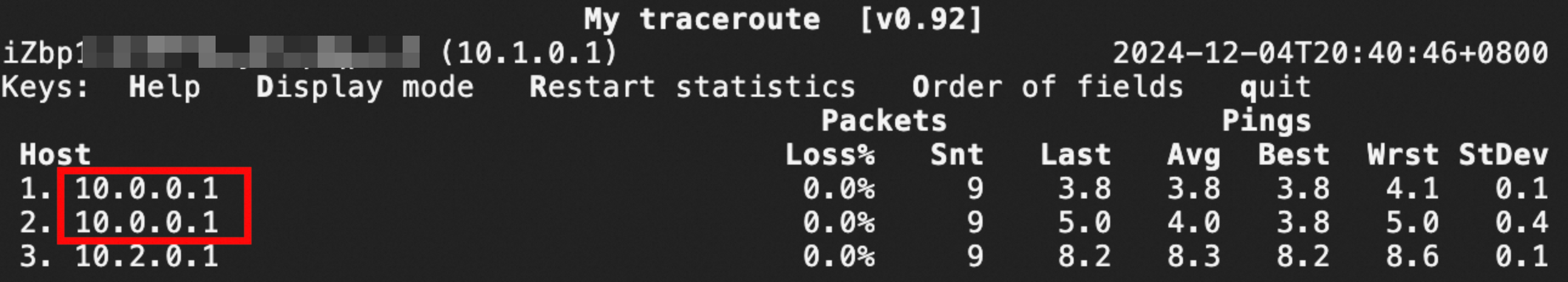
The result shows that packets sent from ECS2 to ECS3 are forwarded through 10.0.0.1 (ECS1). This indicates that traffic between VPC2 and VPC3 is routed through ECS1 (the security ECS instance).
Step 3: Release the resources
After you complete the verification, if you no longer need the resources, run the following command to release them. This prevents you from incurring further charges.
terraform destroy --auto-approve