By Chen Guangsheng, an Apache RocketMQ Committer, the founder of DeFiBus, a technical expert of WeBank, and the head of middleware platform-related products. He was responsible for the construction of operator clouds and big data platforms.
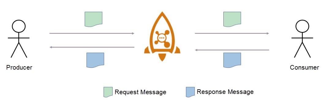
Figure 1.1. Request-Reply mode
Previously, when you used message-oriented middleware (MOM), the producer and consumer only sent and consumed messages, but did not communicate with each other. The Request-Reply mode allows a producer to send a message and then synchronously or asynchronously wait for the consumer to consume the message and return a response. This call effect is similar to the effect of a remote procedure call (RPC). During the Request-Reply call process (RR call for short), the producer sends a message first, and then the message will be retrieved and consumed by the consumer through the broker. After the consumer has consumed the message, the response to this message is sent as another message to the producer. For the convenience of description, the producer, in this case, is called the request end, and the sent message is the "request message". Meanwhile, the consumer is called the service end, and the message returned is called the "response message".
The Request-Reply mode enables RocketMQ to support synchronous calls and expands the application scenarios of RocketMQ, making it possible for more applications. Developers may use this feature to quickly build their own message service buses and implement their RPC calling frameworks. Requests are stored in the broker as messages, so it is convenient to collect information for tracking and analysis. This mode is also widely used in the microservice field.
The RR call involves three roles: producer, broker, and consumer.
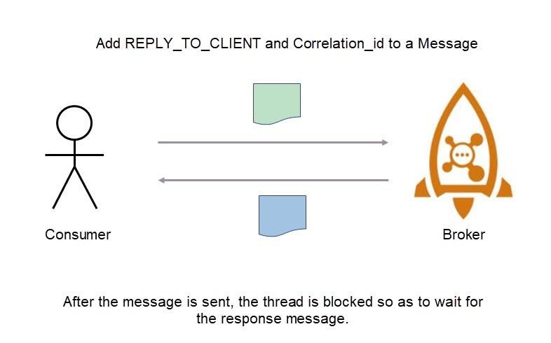
Figure 2.1. Schematic diagram of producer
1) Add the corresponding identifier to the request message.
When the producer sends a request, the identifier for the RR call must be added to the Properties of the message. Here, the key fields are Correlation_Id and REPLY_TO_CLIENT. Correlation_Id uniquely identifies an RR request. It is used to match request messages and response messages of the same RR call. REPLY_TO_CLIENT is used to identify the sender of the request message. Its value is the ClientId of the producer.
As the request-end, the producer only needs to add a corresponding identifier to the message. The logic of sending a message is consistent with the logic of the original producer.
2) Wait for the response message after sending the request message.
Each time after the request-end handles a request, it creates a RequestResponseFuture object and stores it in ResponseFutureTable with Correlation_Id as the key. The request execution thread is blocked by the CountDownLatch parameter defined in RequestResponseFuture. When the response message is returned to the producer, the system retrieves ResponseFutureTable from RequestResponseFuture based on the Correlation_Id in the response message so as to activate CountDownLatch, wake up blocked threads, and process the response message.
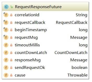
Figure 2.2. Structure of RequestResponseFuture
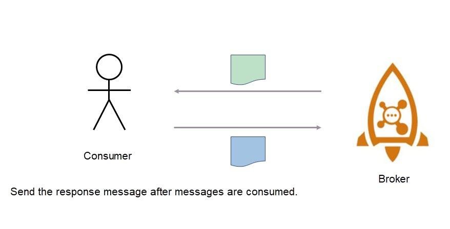
Figure 2.3. Schematic diagram of a consumer
The consumer only needs to create a response message and send it after correctly consuming the request message. When you create the response message, you must use the given utility class to avoid losing the Correlation_Id, REPLY_TO_CLIENT, and other identity properties associated with the RR request.

Figure 2.4. Schematic diagram of broker
The broker handles the request message in the same way as the original processing logic. However, for a response message, the broker actively pushes the message to the request end in Push mode. As the service-end, the consumer sends a response message to Reply_topic, and then the broker forwards the response message to ReplyMessageProcessor for further processing. The processor sends the response message to CommitLog and obtains the ClientId of the request end based on the REPLY_TO_CLIENT in the response message. Then, the processor locates the producer and its channel based on the ClientId and pushes the response message directly to the request end.
All response messages are sent to Reply_topic. This topic is a system topic automatically created by the broker and is named in the "cluster name_REPLY_TOPIC" format. Reply_topic is used for route discovery and allows response messages to be sent back to the cluster from where requests came. This ensures that the broker where the response messages flow is connected to the request end. The purpose of using the broker to actively push response messages is to ensure that the response messages can be returned to the exact instance that sent request messages.
Financial businesses require continuous and stable services 24/7. In addition, they require strong fault tolerance to quickly shield node failures, ensure the success rate, and quickly restore. Based on this specific application scenario, WeBank adds multiple features, such as active application redundancy, proximity-based service, and circuit breaker, to build a secure and reliable financial-grade message bus called DeFiBus.
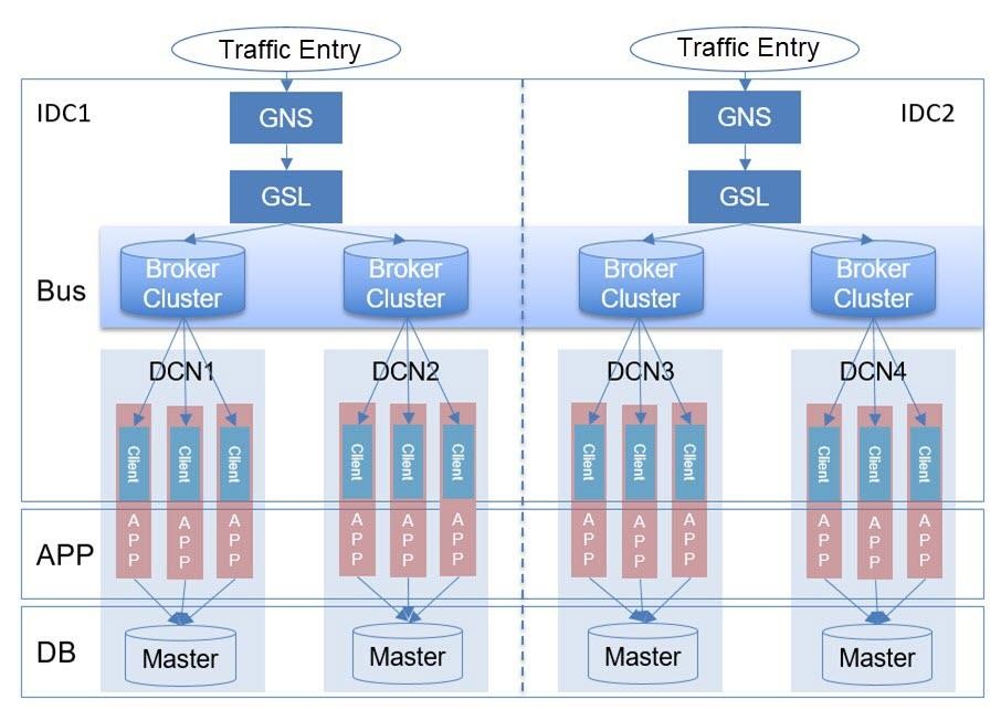
Figure 3.1. The architecture of the bus
As shown in the figure, from top-down, DeFiBus is divided into the bus layer, application layer, and database layer.
The bus layer hosts two important services, GNS and GSL. For each customer, the system distributes weights to planned data collection nodes (DCNs) based on the customer information and weights to implement data sharding. The GNS service addresses all shards at the data level to determine the DCN address of the customer. At the service level, different services are deployed to different regions. When GNS calls a service, it first accesses the GSL service, addresses the shards on the service level, and determines the DCN where the service to be accessed is located. Sharding is performed from the data and service dimensions. GNS and GSL are used for shard addressing, and finally, the request is automatically routed from the bus to the target DCN.
Requests are routed through GNS and GSL from the traffic ingress. After the DCN where the service is located is determined, the bus automatically routes the requests to the region of the DCN where the service runs. Applications within each DCN only process requests in the current DCN. During this process, the applications access the pre-allocated primary database in the same DCN, and the database layer creates multiple replicas to improve reliability.
To improve service availability and reliability, DeFiBus developers have made optimizations and transformations for Request-Reply.
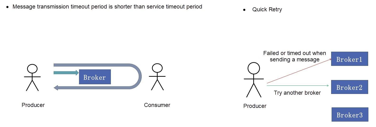
Figure 3.2. Schematic diagram of fast fail-and-retry
From the users' perspective, the service timeout period is the same as the service timeout period of an RR call. An RR call involves two internal message transmission procedures. When the broker fails, a message transmission timeout may occur. Therefore, the timeout period of internal messages is automatically adjusted to a smaller value based on the service timeout period, which leaves more time for fail-and-retry. For example, if the service timeout period is three seconds, set the timeout period of sending a message to one second. Adjust the timeout period of sending a message to quickly locate broker faults. If a broker fails, the producer immediately switches to another broker and isolates the faulty broker. Before the isolation ends, the producer no longer sends messages to the isolated broker.
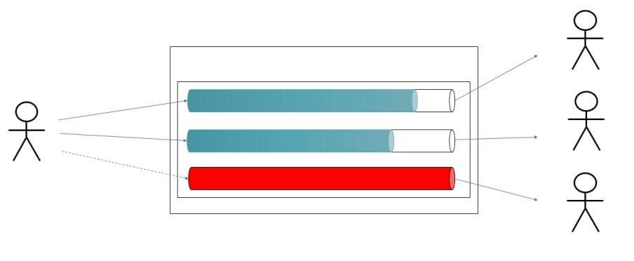
Figure 3.3. Schematic diagram of circuit breaker
When the volume of messages accumulated in a queue reaches a specified threshold, no more messages are sent to the queue, causing a circuit breaker in the corresponding service instances of the queue.
To implement the circuit breaker mechanism, the "queue depth" attribute is added to the queue. Queue depth refers to the number of messages accumulated in a broker in a queue. These messages are not yet pulled by consumers. When the consumer fails or becomes abnormal, the throttling mechanism of the client is triggered first, and the message pulling request is continuously postponed. As a result, messages are accumulated in the broker. When the broker detects that the number of messages accumulated in a queue exceeds the threshold, the queue is marked for circuit breaking. When the producer sends a message, if the target queue is already marked for circuit breaking, the producer receives the response code for the suspension, retries immediately to send the message to another queue, and marks the suspended queue as isolated. Before the isolation is removed, the producer will no longer send messages to the isolated queue.
The queue-level isolation mechanism is mainly used as the circuit breaker mechanism of the producer's retries and services.

Figure 3.4. Schematic diagram of isolation
When a broker fails, the consumer pulls messages and triggers the isolation mechanism. In the consumer implementation of the native RocketMQ, a single thread of PullMessageService sends message pulling requests to all brokers. When a node of these brokers fails, the PullMessageService thread will be temporarily blocked because it establishes a connection with the faulty broker or the request-response slows down, which increases the message processing time of other normal brokers or even makes them time out. Therefore, the developers have added an alternate thread to pull messages. If a message pulling request is detected that has run a longer time than the threshold, the broker is marked as isolated. Meanwhile, all corresponding requests for message pulling are forwarded to the standby thread for execution, ensuring that all PullMessageService requests are sent to the healthy broker. The thread isolation mechanism is used to ensure that the failure of one broker does not affect the message pulling timeliness of the consumer.
Dynamic scaling is designed to ensure that the number of queues remains consistent with the number of consumers. Hence, the number of queues consumed by each consumer after load balancing is consistent. When the producer evenly sends data, loads of consumers remain balanced even with different numbers of allocated queues.
Scale-out or scale-in is achieved by dynamically adjusting the ReadQueueNum or WriteQueueNum value in the topic configuration.
Increase the number of readable queues to ensure that the consumer finishes listening first, and then increase the number of writable queues so that the producer can send messages to the newly added queues.
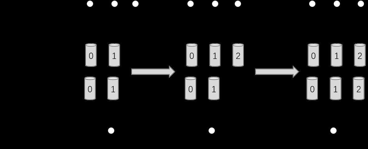
Figure 3.5. Schematic diagram of queue scale-out
The scale-in process of a queue is opposite to the scale-out process. First, the number of writable queues is reduced, and then messages are no longer sent to queues to be scaled in. When the consumer has consumed all the messages in the queues, reduce the number of readable queues to complete the scale-in process.
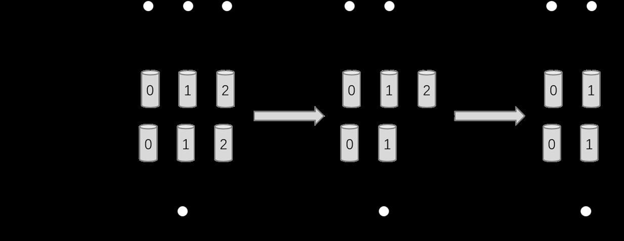
Figure 3.6. Schematic diagram of queue scale-in
When the load balancing result changes, the consumer of RocketMQ directly updates the old result to the new result, which is a jump process from A to B. If there are many consumers and brokers, the numbers of consumers and queues obtained by different consumers during load balancing may be inconsistent, resulting in inconsistent load balancing results. When the results are inconsistent, the queues may encounter problems such as missed messages and repeated messages in the listening process. For synchronous call scenarios, when you miss listening to a message in the queue, the message processing of the queue takes a long time or even times out, resulting in a call failure.
During load balancing transition, a transition state is added to the change process of the load balancing result. In the transition state, the consumer will keep the results of the last load balancing. The old result is not released until the end of a load balancing cycle or when the consumer detects that a new owner is already listening to the queue.
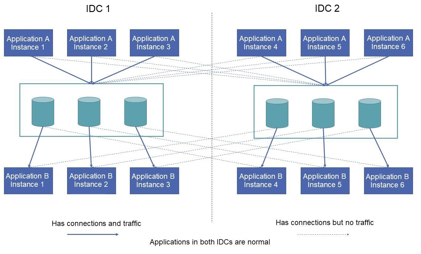
Figure 3.7. Schematic diagram of load balancing transition
To meet the requirements of high availability and disaster recovery, services are deployed in at least two Internet data centers (IDCs). When service in one IDC fails and becomes unavailable, a healthy instance in another IDC automatically takes over the traffic. During deployment, the request end and service end are deployed in both IDCs. When both centers are normal, the request end sends a request to the same IDC according to the principle of proximity-based service. Cross-IDC connections are maintained only through heartbeats. The service provider preferentially listens to the queues in the same IDC during the subscription.
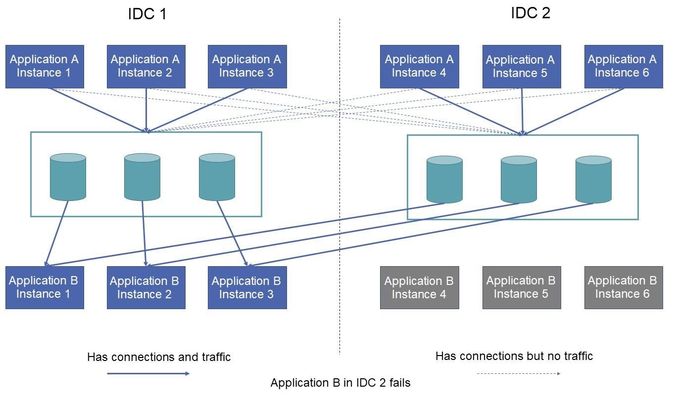
Figure 3.8. Schematic diagram of proper IDC running
A service provider works across IDCs to take over the queues of another IDC only when there are no active service instances in the other IDC. As shown in the figure, when all instances of Application B in IDC 2 fail, instances 1, 2, and 3 deployed in IDC 1 first allocate queues in the same IDC during load balancing. Then, these instances will check and detect that IDC 2 have queues but no active instances of Application B. In this case, the queues of IDC 2 are allocated to instances in IDC 1, allowing the instances to automatically take over services across IDCs.
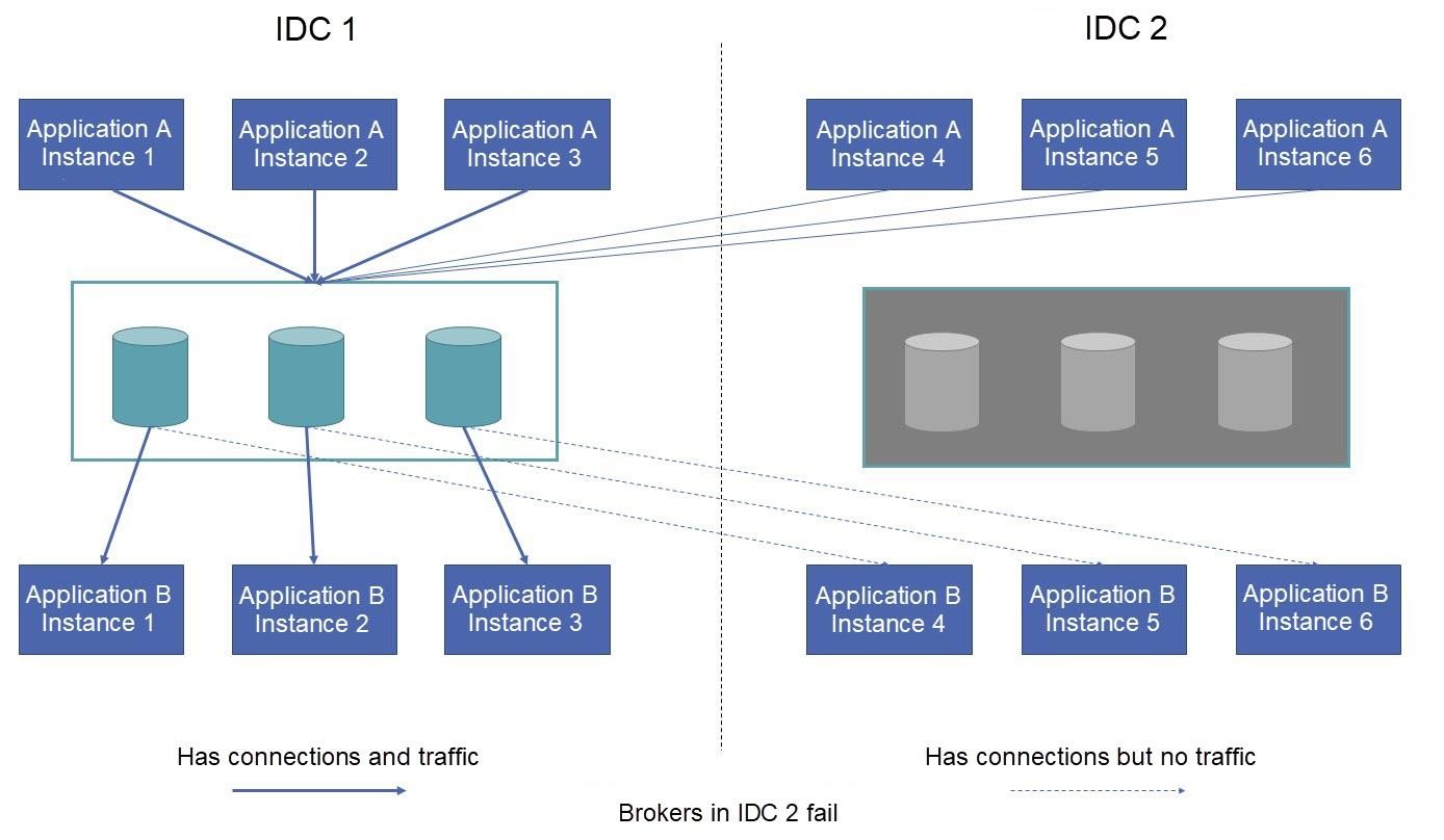
Figure 3.9. Schematic diagram of an improper application running
When all brokers in an IDC fail, the request end sends a message across IDCs. As shown in the figure, when all the brokers in IDC 2 fail, instances 4 to 6 of application A send requests to IDC 1 based on the principle of service proximity. These requests are processed by instances 1 to 3 of application B in IDC 1. This ensures that requests from IDC 2 can also be correctly processed when the brokers fail.
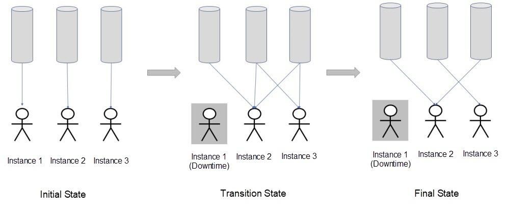
Figure 3.10. Schematic diagram of broker failure
This article mainly introduced the Request-Reply mode, which is a new feature of RocketMQ. In this mode, after messages are sent, the producer waits for the consumer to consume all messages and return a response message, which produces an effect similar to the RPC call. The Request-Reply mode allows RocketMQ to call messages synchronously. On this foundation, developers can develop more new features. To better support financial scenarios, WeBank adds multiple features, such as active application redundancy, proximity-based service, and circuit breaker, in order to build a secure and reliable financial-grade message bus called DeFiBus. At present, most of the achievements have been made open-source by WeBank through DeFiBus. More general practice summaries and achievements in sharding and addressing will be introduced in the future.
Common Solutions for Scheduling and Delay Problems in Business Scenarios

212 posts | 13 followers
FollowAlibaba Clouder - January 4, 2021
Alibaba Cloud Native - June 6, 2024
Alibaba Cloud Native - June 7, 2024
Alibaba Developer - December 17, 2018
Alibaba Cloud Native Community - February 7, 2023
Alibaba Cloud Native Community - November 23, 2022

212 posts | 13 followers
Follow Microservices Engine (MSE)
MSE provides a fully managed registration and configuration center, and gateway and microservices governance capabilities.
Learn More ApsaraMQ for RocketMQ
ApsaraMQ for RocketMQ is a distributed message queue service that supports reliable message-based asynchronous communication among microservices, distributed systems, and serverless applications.
Learn More Server Load Balancer
Respond to sudden traffic spikes and minimize response time with Server Load Balancer
Learn MoreMore Posts by Alibaba Cloud Native