This topic describes how to use Data Transmission Service (DTS) to synchronize data between a data center and a virtual private cloud (VPC) over a VPN gateway.
Scenario
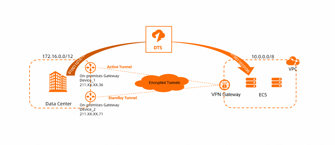
An enterprise has a VPC and a data center, both located in Hohhot. The enterprise has deployed databases in both the data center and the VPC, and wants to automatically synchronize data from the on-premises database to the cloud database in the VPC.
The enterprise can use a VPN gateway to establish an IPsec-VPN connection, which provides an encrypted tunnel between the data center and the VPC. Then, it can use DTS to automatically synchronize data over this encrypted connection.
Prerequisites
You must create a VPC in the China (Hohhot) region and deploy a database on an Elastic Compute Service (ECS) instance within the VPC. For more information, see Create a VPC.
The following table describes the network configurations of the data center and the VPC.
When you plan the network, ensure that the CIDR blocks of the data center and the VPC do not overlap.
Resource | CIDR block | IP address | Database account |
Data center | 172.16.0.0/12 |
|
|
VPC | 10.0.0.0/8 | IP address of the ECS instance that hosts the database: 10.0.0.252 |
|
Procedure
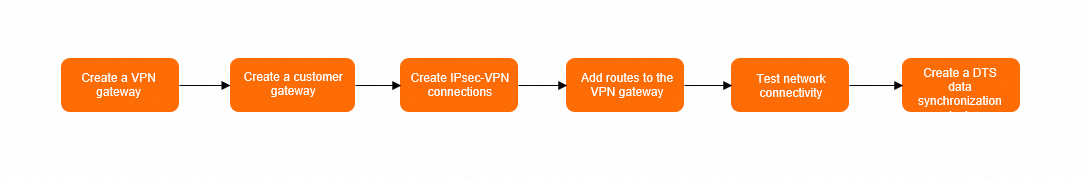
Step 1: Create a VPN gateway
Log on to the VPN Gateway console.
In the top navigation bar, select the region where you want to create the VPN gateway.
The VPN gateway must be in the same region as the VPC that you want to connect.
On the VPN Gateways page, click Create VPN Gateway.
On the buy page, configure the following parameters, click Buy Now, and then complete the payment.
Parameter
Description
Example
Name
Enter a name for the VPN gateway.
In this example, VPNGW is used.
Resource Group
Select the resource group to which the VPN gateway belongs.
If you leave this parameter empty, the VPN gateway belongs to the default resource group.
In this example, this parameter is left empty.
Region
Select the region in which you want to create the VPN gateway.
In this example, China (Hohhot) is selected.
Gateway Type
Select a gateway type.
In this example, Standard is selected.
Network Type
Select a network type for the VPN gateway.
Public: The VPN gateway can be used to establish VPN connections over the Internet.
Private: The VPN gateway can be used to establish VPN connections over private networks.
In this example, Public is selected.
Tunnels
Select a tunnel mode. Valid values:
Dual-tunnel
Single-tunnel
For more information about the single-tunnel mode and dual-tunnel mode, see [Upgrade notice] IPsec-VPN connections support the dual-tunnel mode.
In this example, the default value Dual-tunnel is used.
VPC
Select the VPC that you want to associate with the VPN gateway.
In this example, the VPC deployed in the China (Hohhot) region is selected.
VSwitch
Select a vSwitch from the selected VPC.
If you select Single-tunnel, you need to specify only one vSwitch.
If you select Dual-tunnel, you need to specify two vSwitches.
After the IPsec-VPN feature is enabled, the system creates an elastic network interface (ENI) for each of the two vSwitches as an interface to communicate with the VPC over an IPsec-VPN connection. Each ENI occupies one IP address in the vSwitch.
NoteThe system selects a vSwitch by default. You can change or use the default vSwitch.
After a VPN gateway is created, you cannot modify the vSwitch associated with the VPN gateway. You can view the vSwitch associated with the VPN gateway, the zone to which the vSwitch belongs, and the ENI in the vSwitch on the details page of the VPN gateway.
In this example, a vSwitch in the VPC is selected.
vSwitch 2
Select another vSwitch from the selected VPC.
Specify two vSwitches in different zones in the associated VPC to implement disaster recovery across zones for IPsec-VPN connections.
For a region that supports only one zone, disaster recovery across zones is not supported. We recommend that you specify two vSwitches in the zone to implement high availability of IPsec-VPN connections. You can also select the same vSwitch as the first one.
NoteIf only one vSwitch is deployed in the VPC, create a vSwitch. For more information, see Create and manage vSwitches.
In this example, another vSwitch in the VPC is selected.
Maximum Bandwidth
Select a maximum bandwidth value for the VPN gateway. Unit: Mbit/s.
In this example, the default value is used.
Traffic
Select a metering method for the VPN gateway. Default value: Pay-by-data-transfer.
For more information, see Billing.
In this example, the default value is used.
IPsec-VPN
Specify whether to enable IPsec-VPN. Default value: Enable.
In this example, Enable is selected.
SSL-VPN
Specify whether to enable SSL-VPN. Default value: Disable.
In this example, Disable is selected.
Duration
Select a billing cycle for the VPN gateway. Default value: By Hour.
In this example, the default value is used.
Service-linked Role
Click Create Service-linked Role. The system automatically creates the service-linked role AliyunServiceRoleForVpn.
The VPN gateway assumes this role to access other cloud resources.
If Created is displayed, the service-linked role is created and you do not need to create it again.
Configure this parameter based on actual conditions.
Return to the VPN Gateways page to view the VPN gateway that you created.
When you create a VPN gateway, its initial status is Preparing. After about 1 to 5 minutes, the status changes to Normal, which indicates that the VPN gateway is initialized and ready for use.
The system assigns two public IP addresses to the VPN gateway to establish two encrypted tunnels. The following table lists the two public IP addresses that are assigned in this example.
VPN name
VPN ID
Public IP of the IPsec-VPN connection tunnel
VPNGW
vpn-bp1ox1xu1jo8m1ph0****
47.XX.XX.3
47.XX.XX.169
Step 2: Create a customer gateway
In the left-side navigation pane, choose .
In the top navigation bar, select the region in which you want to create the customer gateway.
Make sure that the customer gateway and the VPN gateway to be connected are deployed in the same region.
On the Customer Gateways page, click Create Customer Gateway.
In the Create Customer Gateway panel, configure the following parameters and click OK.
You must create two customer gateways in order to create two encrypted tunnels. The following table describes only the parameters that are relevant to this topic. You can use the default values for other parameters or leave them empty. For more information, see Customer gateway.
Parameter
Description
Customer Gateway 1
Customer Gateway 2
Name
Enter a name for the customer gateway.
For Customer Gateway 1, CustomerGW1 is used.
For Customer Gateway 2, CustomerGW2 is used.
IP Address
Enter the public IP address of the gateway device in the data center.
For Customer Gateway 1, 211.XX.XX.36 is used.
For Customer Gateway 2, 211.XX.XX.71 is used.
Step 3: Create an IPsec-VPN connection
After you create the VPN gateway and customer gateways, you must create an IPsec-VPN connection to establish encrypted VPN tunnels. The procedure varies based on the Internet Key Exchange (IKE) version that the IPsec-VPN connection uses.
Use IKEv2
In the left-side navigation pane, choose .
On the IPsec Connections page, click Bind VPN Gateway.
On the Create IPsec-VPN Connection page, set the parameters for the IPsec-VPN connection and click OK.
Parameter
Description
Example
Name
Enter a name for the IPsec-VPN connection.
Enter IPsec-Connection.
Region
Select the region where the VPN gateway to be associated with the IPsec-VPN connection is deployed.
The IPsec-VPN connection is created in the same region as the VPN gateway.
Select China (Hohhot).
Bind VPN Gateway
Select the VPN gateway to connect to the IPsec-VPN connection.
Select VPNGW.
Routing Mode
Select a routing mode.
Destination Routing Mode: Forwards traffic based on destination IP addresses.
Protected Data Flows: Forwards traffic based on specific source IP addresses and destination IP addresses.
Select Protected Data Flows
Local Network
Enter the CIDR blocks of the VPC that is connected to the VPN gateway.
Enter the following two CIDR blocks:
VPC CIDR block: 10.0.0.0/8
DTS CIDR block: 100.104.0.0/16
ImportantYou must also add the CIDR blocks that are used by DTS to the Local Network section. This allows DTS to access the peer database through the VPN gateway.
For more information about the CIDR blocks used by DTS, see Add the CIDR blocks of DTS servers.
Remote Network
Enter the CIDR blocks of the peer that you want the VPC to connect to.
Enter 172.16.0.0/12.
Effective Immediately
Specifies whether the configuration takes effect immediately. Valid values:
Yes: Negotiation starts immediately after the configuration is complete.
No: Negotiation starts when traffic is detected.
Select Yes.
BGP Configuration
If the IPsec-VPN connection needs to use the Border Gateway Protocol (BGP), enable this feature. By default, BGP is disabled.
In this example, the default value is used, which means BGP is disabled.
Tunnel 1
Add VPN configurations for Tunnel 1 (the active tunnel).
By default, Tunnel 1 is the active tunnel and Tunnel 2 is the standby tunnel. You cannot change this setting.
Customer Gateway
Select the customer gateway to connect to the active tunnel.
Select CustomerGW1.
Pre-Shared Key
Enter the authentication key for the active tunnel. This key is used for identity authentication.
The key must be 1 to 100 characters in length and can contain digits, letters, and the following special characters:
~`!@#$%^&*()_-+={}[]\|;:',.<>/?.If you do not specify a pre-shared key, the system randomly generates a 16-character string as the pre-shared key.
ImportantThe pre-shared key configured for the tunnel must be the same as the key configured on the peer gateway device. Otherwise, the IPsec-VPN connection cannot be established.
Enter fddsFF123****.
Encryption Configuration
Add configurations for IKE, IPsec, Dead Peer Detection (DPD), and NAT traversal.
The default values are used in this example. For more information about the default values, see Create and manage an IPsec-VPN connection in dual-tunnel mode.
Tunnel 2
Add VPN configurations for Tunnel 2 (the standby tunnel).
Customer Gateway
Select the customer gateway to connect to the standby tunnel.
Select CustomerGW2.
Pre-Shared Key
Enter the authentication key for the standby tunnel. This key is used for identity authentication.
Enter fddsFF456****.
Encryption Configuration
Add configurations for IKE, IPsec, DPD, and NAT traversal.
The default values are used in this example. For more information, see Create and manage an IPsec-VPN connection in dual-tunnel mode.
In the Creation Success dialog box, click OK.
On the IPsec Connections page, find the IPsec-VPN connection that you create and click Generate Peer Configuration in the Actions column.
The configurations of the IPsec peer refer to the VPN configurations that you need to add when you create the IPsec-VPN connection. In this example, you need to add the VPN configurations to the gateway device of the data center.
In the IPsec-VPN Connection Configuration dialog box, copy and save the configurations to an on-premises machine. The configurations are required when you configure the gateway device of the data center.
Use IKEv1
In the left-side navigation pane, choose .
On the IPsec Connections page, click Bind VPN Gateway.
On the Create IPsec-VPN Connection page, set the parameters for the IPsec-VPN connection and click OK.
When you use IKEv1, an IPsec-VPN connection does not support multiple CIDR blocks. You must create two IPsec-VPN connections to transmit DTS traffic and VPC traffic separately.
Parameter
Description
IPsec-VPN Connection 1
IPsec-VPN Connection 2
Name
Enter a name for the IPsec-VPN connection.
Enter IPsec-Connection1.
Enter IPsec-Connection2.
Region
Select the region where the VPN gateway to be associated with the IPsec-VPN connection is deployed.
The IPsec-VPN connection is created in the same region as the VPN gateway.
Select China (Hohhot).
Select China (Hohhot).
Bind VPN Gateway
Select the VPN gateway to connect to the IPsec-VPN connection.
Select VPNGW.
Select VPNGW.
Routing Mode
Select a routing mode.
Destination-based: Forwards traffic based on destination IP addresses.
Policy-based: Forwards traffic based on specific source IP addresses and destination IP addresses.
Select Stream Pattern of Interest.
Select Interested Stream Pattern.
Local Network
Enter the CIDR blocks of the VPC that is connected to the VPN gateway.
Enter the VPC CIDR block: 10.0.0.0/8
Enter the DTS CIDR block: 100.104.0.0/16
ImportantYou must also add the CIDR blocks that are used by DTS to the Local Network section. This allows DTS to access the peer database through the VPN gateway.
For more information about the CIDR blocks used by DTS, see Add the CIDR blocks of DTS servers.
Remote Network
Enter the CIDR blocks of the peer that you want the VPC to connect to.
Enter 172.16.0.0/12.
Enter 172.16.0.0/12.
Effective Immediately
Specifies whether the configuration takes effect immediately. Valid values:
Yes: Negotiation starts immediately after the configuration is complete.
No: Negotiation starts when traffic is detected.
Select Yes.
Select Yes.
BGP Configuration
If the IPsec-VPN connection needs to use BGP, enable this feature. By default, BGP is disabled.
In this example, the default value is used, which means BGP is disabled.
In this example, the default value is used, which means BGP is disabled.
Tunnel 1
Add VPN configurations for Tunnel 1 (the active tunnel).
By default, Tunnel 1 is the active tunnel and Tunnel 2 is the standby tunnel. You cannot change this setting.
Customer Gateway
Select the customer gateway to connect to the active tunnel.
Select CustomerGW1.
Select CustomerGW1.
Pre-Shared Key
Enter the authentication key for the active tunnel. This key is used for identity authentication.
The key must be 1 to 100 characters in length and can contain digits, letters, and the following special characters:
~`!@#$%^&*()_-+={}[]\|;:',.<>/?.If you do not specify a pre-shared key, the system randomly generates a 16-character string as the pre-shared key.
ImportantThe pre-shared key configured for the tunnel must be the same as the key configured on the peer gateway device. Otherwise, the IPsec-VPN connection cannot be established.
Enter fddsFF123****.
Enter fddsFF123****.
Encryption Configuration
Add configurations for IKE, IPsec, DPD, and NAT traversal.
Use IKEv1 and the default values for other parameters. For more information about the default values, see Create and manage an IPsec-VPN connection in dual-tunnel mode.
Use IKEv1 and the default values for other parameters. For more information about the default values, see Create and manage an IPsec-VPN connection in dual-tunnel mode.
Tunnel 2
Add VPN configurations for Tunnel 2 (the standby tunnel).
Customer Gateway
Select the customer gateway to connect to the standby tunnel.
Select CustomerGW2.
Select CustomerGW2.
Pre-Shared Key
Enter the authentication key for the standby tunnel. This key is used for identity authentication.
Enter fddsFF456****.
Enter fddsFF456****.
Encryption Configuration
Add configurations for IKE, IPsec, DPD, and NAT traversal.
Use IKEv1 and the default values for other parameters. For more information about the default values, see Create and manage an IPsec-VPN connection in dual-tunnel mode.
Use IKEv1 and the default values for other parameters. For more information about the default values, see Create and manage an IPsec-VPN connection in dual-tunnel mode.
In the Creation Success dialog box, click OK.
On the IPsec Connections page, find the IPsec-VPN connection that you create and click Generate Peer Configuration in the Actions column.
The configurations of the IPsec peer refer to the VPN configurations that you need to add when you create the IPsec-VPN connection. In this example, you need to add the VPN configurations to the gateway device of the data center.
In the IPsec-VPN Connection Configuration dialog box, copy and save the configurations to an on-premises machine. The configurations are required when you configure the gateway device of the data center.
Step 4: Configure routes for the VPN gateway
After creating the IPsec-VPN connection, you must configure routes for the VPN gateway to enable communication. If you set Routing Mode to Policy-based when you created the IPsec-VPN connection, the system automatically creates policy-based routes with an Unpublished status. You must publish all policy-based routes from the VPN gateway to the VPC.
In the left-side navigation pane, choose .
In the top navigation bar, select the region where the VPN gateway instance resides.
On the VPN Gateways page, click the ID of the target VPN gateway.
On the details page of the VPN gateway, click the Policy-based Route Table tab, find the route that you want to manage, and then click Advertise in the Actions column.
In the Advertise Route dialog box, click OK.
Step 5: Configure the on-premises gateway devices
After creating the IPsec-VPN connection, you must add VPN and routing configurations to your on-premises gateway devices. This step establishes the IPsec-VPN connection between the on-premises gateway devices and the VPN gateway. It also ensures that traffic from the data center to the VPC is preferentially sent through the active tunnel. If the active tunnel fails, traffic is automatically switched to the standby tunnel.
The following content contains information about third-party products. This information is for reference only. Alibaba Cloud does not make any warranties, express or implied, with respect to the performance and reliability of third-party products, or the potential impacts of operations on these products.
The commands may vary based on the device vendor. For specific commands, contact the device vendor.
Use IKEv2
Add the peer configuration that you saved to your on-premises gateway devices.
Log on to the command-line interface (CLI) of the on-premises gateway device.
Run the following commands to configure the IKEv2 proposal and policy.
//Add the following configurations to on-premises gateway device 1 and on-premises gateway device 2.
crypto ikev2 proposal alicloud
encryption aes-cbc-128          //Configure the encryption algorithm. In this example, aes-cbc-128 is used.
integrity sha1                  //Configure the authentication algorithm. In this example, sha1 is used.
group 2                         //Configure the DH group. In this example, group 2 is used.
exit
!
crypto ikev2 policy Pureport_Pol_ikev2
proposal alicloud
exit
!
Run the following commands to configure the IKEv2 keyring.
//Add the following configuration to on-premises gateway device 1.
crypto ikev2 keyring alicloud
peer alicloud
address 47.XX.XX.3               //The public IP address of the active tunnel for the IPsec-VPN connection. In this example, 47.XX.XX.3 is used.
pre-shared-key fddsFF123****     //Configure the pre-shared key. In this example, fddsFF123**** is used.
exit
!
//Add the following configuration to on-premises gateway device 2.
crypto ikev2 keyring alicloud
peer alicloud
address 47.XX.XX.169               //The public IP address of the standby tunnel for the IPsec-VPN connection. In this example, 47.XX.XX.169 is used.
pre-shared-key fddsFF456****     //Configure the pre-shared key. In this example, fddsFF456**** is used.
exit
!
Run the following commands to configure the IKEv2 profile.
//Add the following configuration to on-premises gateway device 1.
crypto ikev2 profile alicloud
match identity remote address 47.XX.XX.3 255.255.255.255    //Match the public IP address of the active tunnel of the IPsec-VPN connection. In this example, 47.XX.XX.3 is used.
identity local address 211.XX.XX.36    //The public IP address of on-premises gateway device 1. In this example, 211.XX.XX.36 is used.
authentication remote pre-share   //The authentication method for the peer is PSK (pre-shared key).
authentication local pre-share    //The authentication method for the local end is PSK.
keyring local alicloud            //Call the keyring.
exit
!
//Add the following configuration to on-premises gateway device 2.
crypto ikev2 profile alicloud
match identity remote address 47.XX.XX.169 255.255.255.255    //Match the public IP address of the standby tunnel of the IPsec-VPN connection. In this example, 47.XX.XX.169 is used.
identity local address 211.XX.XX.71    //The public IP address of on-premises gateway device 2. In this example, 211.XX.XX.71 is used.
authentication remote pre-share   //The authentication method for the peer is PSK (pre-shared key).
authentication local pre-share    //The authentication method for the local end is PSK.
keyring local alicloud            //Call the keyring.
exit
!
Run the following commands to configure the transform set.
//Add the following configurations to on-premises gateway device 1 and on-premises gateway device 2.
crypto ipsec transform-set TSET esp-aes esp-sha-hmac
mode tunnel
exit
!
Configure an access control list (ACL) to define the data streams to be protected.
//Add the following configurations to on-premises gateway device 1 and on-premises gateway device 2.
access-list 100 permit ip 172.16.0.0 0.15.255.255 10.0.0.0 0.255.255.255
Configure the IPsec policy.
//Add the following configuration to on-premises gateway device 1.
crypto map ipsecpro64 10 ipsec-isakmp
set peer 47.XX.XX.3
set transform-set TSET
set ikev2-profile alicloud
set pfs group2
match address 100
//Add the following configuration to on-premises gateway device 2.
crypto map ipsecpro64 10 ipsec-isakmp
set peer 47.XX.XX.169
set transform-set TSET
set ikev2-profile alicloud
set pfs group2
match address 100
Run the following commands to configure the IPsec tunnels.
//Add the following configuration to on-premises gateway device 1.
interface GigabitEthernet1                 //Configure the interface IP address used to establish the active VPN tunnel with the IPsec-VPN connection.
ip address 211.XX.XX.36 255.255.255.0
crypto map ipsecpro64			//Apply the IPsec policy.
negotiation auto
!
//Add the following configuration to on-premises gateway device 2.
interface GigabitEthernet1                 //Configure the interface IP address used to establish the standby VPN tunnel with the IPsec-VPN connection.
ip address 211.XX.XX.71 255.255.255.0
crypto map ipsecpro64		  //Apply the IPsec policy.
negotiation auto
!
Add routing configurations to on-premises gateway device 1 and on-premises gateway device 2.
Add routes that point to the VPC on on-premises gateway device 1 and on-premises gateway device 2.
//Add routes that point to the VPC to on-premises gateway device 1.
ip route 10.0.0.0 255.0.0.0  47.XX.XX.3
ip route 100.104.0.0 255.255.0.0  47.XX.XX.3
//Add routes that point to the VPC to on-premises gateway device 2.
ip route 10.0.0.0 255.0.0.0  47.XX.XX.169
ip route 100.104.0.0 255.255.0.0  47.XX.XX.169
If required by your network environment, add routing configurations to your data center. The routes must allow traffic from the data center to the VPC to be preferentially sent through on-premises gateway device 1. If on-premises gateway device 1 fails, traffic is automatically sent through on-premises gateway device 2. For specific commands, contact the device vendor.
Use IKEv1
Add the peer configuration that you saved to your on-premises gateway devices.
Log on to the CLI of the on-premises gateway device.
Configure the ISAKMP policy.
//Add the following configurations to on-premises gateway device 1 and on-premises gateway device 2.
crypto isakmp policy 1
authentication pre-share
encryption aes
hash sha
group  2
lifetime 86400
Configure the pre-shared key.
//Add the following configuration to on-premises gateway device 1.
crypto isakmp key fddsFF123**** address 47.XX.XX.3
//Add the following configuration to on-premises gateway device 2.
crypto isakmp key fddsFF456**** address 47.XX.XX.169
Configure the IPsec security protocol.
//Add the following configurations to on-premises gateway device 1 and on-premises gateway device 2.
crypto ipsec transform-set ipsecpro64 esp-aes esp-sha-hmac
mode tunnel
Configure an ACL to define the data streams to be protected.
//Add the following configurations to on-premises gateway device 1 and on-premises gateway device 2.
access-list 100 permit ip 172.16.0.0 0.15.255.255 10.0.0.0 0.255.255.255
Configure the IPsec policy.
//Add the following configuration to on-premises gateway device 1.
crypto map ipsecpro64 10 ipsec-isakmp
set peer 47.XX.XX.3
set transform-set ipsecpro64
set pfs group2
match address 100
//Add the following configuration to on-premises gateway device 2.
crypto map ipsecpro64 10 ipsec-isakmp
set peer 47.XX.XX.169
set transform-set ipsecpro64
set pfs group2
match address 100
Apply the IPsec policy.
//Add the following configuration to on-premises gateway device 1.
interface GigabitEthernet1    //Apply the IPsec policy to the interface that is configured with a public IP address.
crypto map ipsecpro64
//Add the following configuration to on-premises gateway device 2.
interface GigabitEthernet1    //Apply the IPsec policy to the interface that is configured with a public IP address.
crypto map ipsecpro64
Add routing configurations to on-premises gateway device 1 and on-premises gateway device 2.
Add routes that point to the VPC on on-premises gateway device 1 and on-premises gateway device 2.
//Add routes that point to the VPC to on-premises gateway device 1.
ip route 10.0.0.0 255.0.0.0  47.XX.XX.3
ip route 100.104.0.0 255.255.0.0  47.XX.XX.3
//Add routes that point to the VPC to on-premises gateway device 2.
ip route 10.0.0.0 255.0.0.0  47.XX.XX.169
ip route 100.104.0.0 255.255.0.0  47.XX.XX.169
If required by your network environment, add routing configurations to your data center. The routes must allow traffic from the data center to the VPC to be preferentially sent through on-premises gateway device 1. If on-premises gateway device 1 fails, traffic is automatically sent through on-premises gateway device 2. For specific commands, contact the device vendor.
Step 6: Test the connectivity
After you complete the configurations, the data center and the VPC can communicate with each other. Perform the following steps to test the connectivity.
Before you test the connectivity, check the security group rules for the ECS instance in the VPC and the access control rules in the data center. Ensure that the security group rules and access control rules allow mutual access between the data center and the VPC. For more information, see Query security group rules and Add a security group rule.
Log on to the ECS instance in the VPC.
About how to log on to an ECS instance, see connection methods for ECS instances.
Run the
pingcommand on the ECS instance to access the database server in the data center.If the ECS instance receives reply messages, it indicates that the data center and the VPC can communicate with each other.
ping <IP address of the database server in the data center>
Step 7: Create a DTS data synchronization task
After communication is established between the data center and the VPC, you can create a DTS data synchronization task. After the task is configured, data from the data center is automatically synchronized to the database in the VPC.
This topic uses data synchronization between MySQL instances as an example. For more information about other synchronization scenarios, see Overview of data synchronization scenarios.
Go to the data synchronization task list page in the destination region. You can do this in one of two ways.
DTS console
Log on to the DTS console.
In the navigation pane on the left, click Data Synchronization.
In the upper-left corner of the page, select the region where the synchronization instance is located.
DMS console
NoteThe actual steps may vary depending on the mode and layout of the DMS console. For more information, see Simple mode console and Customize the layout and style of the DMS console.
Log on to the DMS console.
In the top menu bar, choose .
To the right of Data Synchronization Tasks, select the region of the synchronization instance.
Click Create Task to open the task configuration page.
Optional: In the upper-right corner of the page, click New Configuration Page.
NoteIf you are already on the new configuration page (the button in the upper-right corner is Back to Previous Version), you can skip this step.
Some parameters differ between the new and old configuration pages. We recommend using the new version.
Configure the source and destination databases.
Category
Parameter
Description
N/A
Task Name
DTS automatically generates a task name. We recommend that you specify a descriptive name for easy identification. The name does not need to be unique.
Source Database
Database Type
Select MySQL.
Connection Type
Select Express Connect, VPN Gateway, or Smart Access Gateway.
Instance Region
Select the region where the source MySQL database resides.
In this example, China (Hohhot) is selected.
Replicate Data Across Alibaba Cloud Accounts
Select No.
Connected VPC
Select the VPC in the China (Hohhot) region.
DTS connects to the database in the data center through the VPC and the VPN gateway.
Domain Name or IP
Enter the host IP address of the source MySQL database.
In this example, enter the IP address of the database server in the data center: 172.16.0.228.
Port Number
Enter the service port of the source MySQL database. The port must be accessible over the internet. The default port is 3306.
Database Account
Enter the account for the source MySQL database.
Database Password
Enter the password that corresponds to the database account.
Destination Database
Database Type
Select MySQL.
Connection Type
Select Express Connect, VPN Gateway, or Smart Access Gateway.
Instance Region
Select the region where the destination MySQL database instance resides.
In this example, select China (Hohhot).
Connected VPC
Select the VPC in the China (Hohhot) region.
Domain Name or IP
Enter the host IP address of the destination MySQL database.
In this example, enter the IP address of the ECS instance in the VPC: 10.0.0.252.
Port Number
Enter the service port of the destination MySQL database. The port must be accessible over the internet. The default port is 3306.
Database Account
Enter the database account for the destination MySQL database instance.
Database Password
Enter the password that corresponds to the database account.
After you complete the configuration, click Test Connectivity and Proceed at the bottom of the page.
Ensure that the security group rules for the ECS instance and the ACL rules for the data center allow access from DTS. For more information about the CIDR blocks used by DTS, see Add the CIDR blocks of DTS servers.
WarningAdding the public IP address CIDR blocks of DTS servers, whether automatically or manually, may pose security risks. Using this product, you acknowledge and accept these potential risks. You are responsible for taking basic security measures. These measures include but are not limited to strengthening password security, restricting open ports for each CIDR block, using authentication for internal API calls, and regularly checking for and restricting unnecessary CIDR blocks. You can also connect to DTS over a private network using Express Connect, a VPN gateway, or Smart Access Gateway.
If the connectivity test is successful, it indicates that the network connection between the databases is normal. The system proceeds to the Configure Objects and Advanced Settings page. You can continue to configure the DTS data synchronization task. After the task is configured, you can start to synchronize data. For more information about how to configure the DTS data synchronization task, see Two-way synchronization between MySQL databases.
If the connectivity test fails, you cannot proceed to the next page. Troubleshoot the issue as prompted. For more information, see What do I do if an error is reported when I connect a database instance to DTS over a VPN connection?