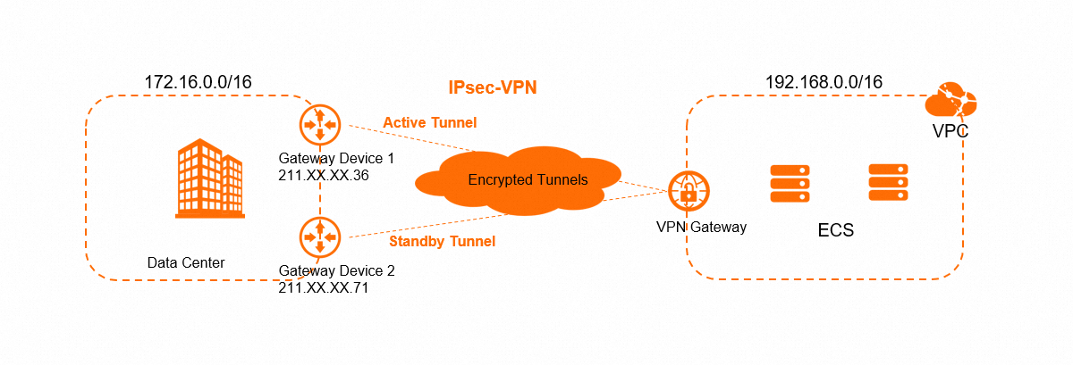
Use a public VPN gateway to create an IPsec-VPN connection in dual-tunnel mode between a VPC and an on-premises data center. Dual-tunnel mode provides high availability: if the active tunnel fails, traffic automatically switches to the standby tunnel. Border Gateway Protocol (BGP) dynamic routing enables automatic route learning between the VPC and data center, reducing manual configuration and the risk of routing errors.
Prerequisites
At least one public IP address assigned to the on-premises gateway device. Two public IP addresses are recommended -- either on one device or across two separate devices -- to support high availability.
The on-premises gateway device supports the IKEv1 or IKEv2 protocol.
The on-premises gateway device supports BGP dynamic routing.
The CIDR block of the data center does not overlap with the CIDR block of the VPC.
Before you begin
Before you begin, make sure that you have:
A VPC in the target region with workloads deployed on Elastic Compute Service (ECS) instances. For instructions, see VPCs and vSwitches
Security group rules on the ECS instances and access control rules on the data center devices configured to allow traffic between the VPC and data center. For details, see Use security groups and Use security groups.
Example
An enterprise has a VPC in the China (Hohhot) region with a primary CIDR block of 192.168.0.0/16. The enterprise also has a data center in Hohhot with a CIDR block of 172.16.0.0/16. Devices in the data center need to access the VPC over an encrypted connection with high availability.
Network planning
Gather the following information before starting configuration. All IP addresses, autonomous system numbers (ASNs), and CIDR blocks in this section are used throughout the procedure.
IP addresses and CIDR blocks
Resource | Value |
VPC primary CIDR block | 192.168.0.0/16 |
Data center CIDR block | 172.16.0.0/16 |
On-premises gateway device 1 public IP | 211.XX.XX.36 |
On-premises gateway device 2 public IP | 211.XX.XX.71 |
BGP configuration
If an IPsec-VPN connection uses BGP dynamic routing, the Local ASN of both tunnels must be the same. The peer ASNs of the two tunnels can differ, but using the same peer ASN is recommended.
Item | Tunnel | ASN | Tunnel CIDR block | BGP IP address |
IPsec-VPN connection | Active (Tunnel 1) | 65530 | 169.254.10.0/30 | 169.254.10.1 |
IPsec-VPN connection | Standby (Tunnel 2) | 65530 | 169.254.20.0/30 | 169.254.20.1 |
Data center | Active (Tunnel 1) | 65500 | 169.254.10.0/30 | 169.254.10.2 |
Data center | Standby (Tunnel 2) | 65500 | 169.254.20.0/30 | 169.254.20.2 |
Pre-shared keys
Tunnel | Pre-shared key |
Active (Tunnel 1) | fddsFF123\*\*\*\*\*\* |
Standby (Tunnel 2) | fddsFF456\*\*\*\*\*\* |
Procedure

Step 1: Create a VPN gateway
Log on to the VPN Gateway console.
In the top navigation bar, select the region where the VPC is deployed. The VPN gateway must be in the same region as the VPC.
On the VPN Gateway page, click Create VPN Gateway.
On the buy page, configure the following parameters, click Buy Now, and complete the payment.
NoteThe system selects a default vSwitch. You can change the selection or keep the default.
After a VPN gateway is created, you cannot modify the associated vSwitches. View the vSwitch, zone, and ENI details on the VPN gateway details page.
Parameter
Description
Example value
Name
Enter a name for the VPN gateway.
VPNGW
Resource Group
Select a resource group. If left blank, the VPN gateway belongs to the default resource group.
Default resource group
Region
Select the region for the VPN gateway.
China (Hohhot)
Gateway Type
Select a gateway type.
Standard
Network Type
Select a network type. Public: establishes VPN connections over the internet. Private: establishes VPN connections over private networks.
Public
Tunnels
Select a tunnel mode. Valid values: Dual-tunnel, Single-tunnel. For details, see Associate an IPsec-VPN connection with a VPN gateway.
Dual-tunnel (default)
VPC
Select the VPC to associate with the VPN gateway.
VPC in China (Hohhot)
VSwitch
Select a vSwitch from the VPC. For dual-tunnel mode, specify two vSwitches. The system creates an elastic network interface (ENI) in each vSwitch. Each ENI occupies one IP address in the vSwitch.
A vSwitch in the VPC
vSwitch 2
Select a second vSwitch. Use vSwitches in different zones for cross-zone disaster recovery. In single-zone regions, select two vSwitches in the same zone, or select the same vSwitch as the first.
Another vSwitch in the VPC
Peak Bandwidth
Select the maximum bandwidth (Mbit/s).
Default value
Traffic
Select a metering method. Default: Pay-by-data-transfer. For details, see Billing overview.
Pay-by-data-transfer
IPsec-VPN
Enable or disable IPsec-VPN. Default: Enable.
Enable
SSL-VPN
Enable or disable SSL-VPN. Default: Disable.
Disable
Duration
Select a billing cycle. Default: By Hour.
By Hour
Service-linked Role
Click Create Service-linked Role. The system creates the AliyunServiceRoleForVpn role, which allows the VPN gateway to access other cloud resources. If Created is displayed, the role already exists.
As needed
On the VPN Gateway page, verify that the VPN gateway is created. The gateway starts in the Preparing state and transitions to Normal within 1 to 5 minutes. After the state changes to Normal, the gateway is ready. A public VPN gateway receives two public IP addresses -- one for each tunnel:
Tunnel
IP address
Tunnel 1 (active)
39.XX.XX.218
Tunnel 2 (standby)
182.XX.XX.19
Step 2: Create customer gateways
Create two customer gateways -- one for each encrypted tunnel.
In the left-side navigation pane, choose Interconnections > VPN > Customer Gateways.
In the top navigation bar, select the same region as the VPN gateway. The customer gateway and VPN gateway must be in the same region.
On the Customer Gateways page, click Create Customer Gateway.
In the Create Customer Gateway panel, configure the following parameters and click OK. Repeat this step to create two customer gateways. For full parameter descriptions, see Customer gateway.
Parameter
Customer gateway 1
Customer gateway 2
Name
CustomerGW1
CustomerGW2
IP Address
211.XX.XX.36
211.XX.XX.71
ASN
65500
65500
Step 3: Create an IPsec-VPN connection
In the left-side navigation pane, choose Interconnections > VPN > IPsec Connections.
On the IPsec Connections page, click Bind VPN Gateway.
On the Create Ipsec-vpn Connection (VPN) page, configure the following parameters and click OK. Tunnel 1 (active tunnel) By default, Tunnel 1 is the active tunnel and Tunnel 2 is the standby tunnel. You cannot change this assignment. Tags: Optionally add tags to the IPsec-VPN connection.
NoteIf BGP is used, we recommend that you set Routing Mode to Destination Routing Mode.
Important- The pre-shared key must match on both the IPsec-VPN connection and the on-premises gateway device. Mismatched keys prevent the tunnel from being established. - Each tunnel on a VPN gateway must use a unique tunnel CIDR block. - The tunnel CIDR block cannot be 169.254.0.0/30, 169.254.1.0/30, 169.254.2.0/30, 169.254.3.0/30, 169.254.4.0/30, 169.254.5.0/30, 169.254.6.0/30, or 169.254.169.252/30. - Match the encryption parameters to your on-premises gateway device. The IKE and IPsec configurations must be identical on both sides.
Basic settings
Parameter
Description
Example value
Name
Enter a name for the IPsec-VPN connection.
IPsec-Connection
Region
Select the region of the VPN gateway. The IPsec-VPN connection is created in the same region.
China (Hohhot)
Resource Group
The resource group of the VPN gateway.
Default resource group
Bind VPN Gateway
Select the VPN gateway.
VPNGW
Routing Mode
Select a routing mode. Destination Routing Mode: forwards traffic based on destination IP. Protected Data Flows: forwards traffic based on source and destination IP.
Destination Routing Mode
Effective Immediately
Yes: starts negotiation immediately. No: starts negotiation when inbound traffic is detected.
Yes
Enable BGP
Turn on to enable BGP dynamic routing for this connection. Disabled by default.
Enabled
Local ASN
The ASN on the VPC side. Default: 45104. Valid range: 1 to 4294967295.
65530
Parameter
Description
Example value
Customer Gateway
Select the customer gateway for the active tunnel.
CustomerGW1
Pre-Shared Key
Enter a pre-shared key for identity verification. Must be 1 to 100 characters. Allowed characters: digits, letters (upper and lowercase), and
~!@#$%^&*()_-+={}[]|;:',.<>/? . Spaces are not allowed. If omitted, the system generates a 16-character key. After the IPsec-VPN connection is created, you can click Edit for the tunnel to view the system-generated key. For more information, see IPsec-VPN connections (VPN Gateway).**fddsFF123\*\*\*\*\*\***
Encryption Configuration
Configure IKE, IPsec, Dead Peer Detection (DPD), and NAT traversal parameters. For full details, see Create and manage an IPsec-VPN connection in dual-tunnel mode.
Set DH Group to group14 in both the IKE Configurations and IPsec Configurations sections. Use defaults for other parameters.
Tunnel CIDR Block
The CIDR block for the BGP session on the active tunnel. Must fall within 169.254.0.0/16 with a /30 subnet mask.
169.254.10.0/30
Local BGP IP address
The BGP IP address within the tunnel CIDR block.
169.254.10.1
Tunnel 2 (standby tunnel)
Parameter
Description
Example value
Customer Gateway
Select the customer gateway for the standby tunnel.
CustomerGW2
Pre-Shared Key
Enter a pre-shared key for the standby tunnel.
**fddsFF456\*\*\*\*\*\***
Encryption Configuration
Same as Tunnel 1.
Set DH Group to group14 in both the IKE Configurations and IPsec Configurations sections. Use defaults for other parameters.
Tunnel CIDR Block
The CIDR block for the BGP session on the standby tunnel.
169.254.20.0/30
Local BGP IP address
The BGP IP address within the tunnel CIDR block.
169.254.20.1
In the Created message, click Cancel.
On the IPsec Connections page, find the IPsec-VPN connection and click Generate Peer Configuration in the Actions column. The peer configuration contains the VPN settings you need to apply to the on-premises gateway devices.
In the IPsec-VPN Connection Configuration dialog box, copy and save the configuration to a local machine. You will use this information in Step 5.
Step 4: Enable BGP dynamic routing
Enable automatic route advertisement so the VPN gateway can learn routes from the data center and advertise them to the VPC.
In the left-side navigation pane, choose Cross-network Interconnection > VPN > VPN Gateways.
In the top navigation bar, select the region of the VPN gateway.
On the VPN Gateways page, find the VPN gateway and turn on the Enable Automatic Route Advertisement switch.
Step 5: Configure the on-premises gateway devices
Add VPN, IPsec, and BGP configurations to the on-premises gateway devices so they can connect to the IPsec-VPN connection. Traffic flows through the active tunnel by default. If the active tunnel fails, the standby tunnel takes over automatically.
This example uses Cisco Adaptive Security Appliance (ASA) software version 9.19.1. Commands may vary across software versions. Consult your vendor documentation for your specific environment. For additional guidance, see Configure an H3C firewall.
The following third-party product information is for reference only. Alibaba Cloud does not guarantee the performance or reliability of third-party products, or the impacts of operations performed with them.
On-premises parameter summary
Before configuring the devices, gather these values from the peer configuration generated in Step 3:
Parameter | Device 1 (active tunnel) | Device 2 (standby tunnel) |
Alibaba Cloud public IP | 39.XX.XX.218 | 182.XX.XX.19 |
On-premises public IP | 211.XX.XX.36 | 211.XX.XX.71 |
Pre-shared key | fddsFF123\*\*\*\*\*\* | fddsFF456\*\*\*\*\*\* |
IKE encryption | aes | aes |
IKE integrity | sha | sha |
IKE DH group | 14 | 14 |
IKE SA lifetime | 86400 seconds | 86400 seconds |
IPsec encryption (ESP) | aes | aes |
IPsec integrity (ESP) | sha-1 | sha-1 |
IPsec PFS DH group | group14 | group14 |
IPsec SA lifetime | 86400 seconds | 86400 seconds |
Tunnel interface IP | 169.254.10.2/30 | 169.254.20.2/30 |
BGP peer IP | 169.254.10.1 | 169.254.20.1 |
Local ASN | 65500 | 65500 |
Remote ASN | 65530 | 65530 |
Advertised network | 172.16.0.0/16 | 172.16.0.0/16 |
Configuration steps
Log on to the Cisco firewall CLI and enter configuration mode.
   ciscoasa> enable
   Password: ********             # Enter the enable mode password.
   ciscoasa# configure terminal   # Enter configuration mode.
   ciscoasa(config)#
Verify interface configurations. Confirm that interfaces are configured and enabled. This example uses the following interfaces:
   # On-premises gateway device 1
   ciscoasa(config)# show running-config interface
   !
   interface GigabitEthernet0/0
    nameif outside1                            # Public-facing interface name.
    security-level 0
    ip address 211.XX.XX.36 255.255.255.255    # Public IP address.
   !
   interface GigabitEthernet0/1                # Interface connecting to the data center.
    nameif private                             # Private interface name.
    security-level 100
    ip address 172.16.50.217 255.255.255.0    # Private IP address.
   !
   # On-premises gateway device 2
   ciscoasa(config)# show running-config interface
   !
   interface GigabitEthernet0/0
    nameif outside1                            # Public-facing interface name.
    security-level 0
    ip address 211.XX.XX.71 255.255.255.255    # Public IP address.
   !
   interface GigabitEthernet0/1                # Interface connecting to the data center.
    nameif private                             # Private interface name.
    security-level 100
    ip address 172.16.40.218 255.255.255.0    # Private IP address.
   !
Enable IKEv2 on the public interfaces. Run this command on both gateway devices:
crypto ikev2 enable outside1 # Enable IKEv2 on the public interface.Create an IKEv2 policy. Specify the authentication algorithm, encryption algorithm, Diffie-Hellman (DH) group, and security association (SA) lifetime. These values must match the Alibaba Cloud configuration. Run this command on both gateway devices:
   crypto ikev2 policy 10
    encryption aes             # Encryption algorithm.
    integrity sha              # Authentication algorithm.
    group 14                   # DH group.
    prf sha                    # Must match the integrity parameter.
    lifetime seconds 86400     # SA lifetime.
Create an IPsec proposal and profile. Specify the encryption algorithm, authentication algorithm, DH group, and SA lifetime for the IPsec phase. These values must match the Alibaba Cloud configuration. Run these commands on both gateway devices:
   crypto ipsec ikev2 ipsec-proposal ALIYUN-PROPOSAL    # Create an IPsec proposal.
    protocol esp encryption aes                         # ESP encryption algorithm.
    protocol esp integrity sha-1                        # ESP authentication algorithm.
   crypto ipsec profile ALIYUN-PROFILE
    set ikev2 ipsec-proposal ALIYUN-PROPOSAL            # Apply the proposal.
    set ikev2 local-identity address                    # Set local ID format to IP address.
    set pfs group14                                     # Perfect Forward Secrecy (PFS) DH group.
    set security-association lifetime seconds 86400     # Time-based SA lifetime.
    set security-association lifetime kilobytes unlimited  # Disable traffic-based SA lifetime.
Create tunnel groups with pre-shared keys. The pre-shared keys must match the values configured on Alibaba Cloud.
   # On-premises gateway device 1 (active tunnel)
   tunnel-group 39.XX.XX.218 type ipsec-l2l
   tunnel-group 39.XX.XX.218 ipsec-attributes
    ikev2 remote-authentication pre-shared-key fddsFF123****
    ikev2 local-authentication pre-shared-key fddsFF123****
   !
   # On-premises gateway device 2 (standby tunnel)
   tunnel-group 182.XX.XX.19 type ipsec-l2l
   tunnel-group 182.XX.XX.19 ipsec-attributes
    ikev2 remote-authentication pre-shared-key fddsFF456****
    ikev2 local-authentication pre-shared-key fddsFF456****
   !
Create tunnel interfaces.
   # On-premises gateway device 1 (active tunnel)
   interface Tunnel1
    nameif ALIYUN1
    ip address 169.254.10.2 255.255.255.252           # Tunnel interface IP.
    tunnel source interface outside1                  # Source: public interface.
    tunnel destination 39.XX.XX.218                   # Destination: Alibaba Cloud Tunnel 1 IP.
    tunnel mode ipsec ipv4
    tunnel protection ipsec profile ALIYUN-PROFILE    # Apply the IPsec profile.
    no shutdown                                       # Enable the interface.
   !
   # On-premises gateway device 2 (standby tunnel)
   interface Tunnel1
    nameif ALIYUN1
    ip address 169.254.20.2 255.255.255.252           # Tunnel interface IP.
    tunnel source interface outside1                  # Source: public interface.
    tunnel destination 182.XX.XX.19                   # Destination: Alibaba Cloud Tunnel 2 IP.
    tunnel mode ipsec ipv4
    tunnel protection ipsec profile ALIYUN-PROFILE    # Apply the IPsec profile.
    no shutdown                                       # Enable the interface.
   !
Configure routes and BGP. After completing these configurations, the IPsec-VPN connection is established. The data center and VPN gateway learn routes from each other through BGP.
   # On-premises gateway device 1 (active tunnel)
   route outside1 39.XX.XX.218 255.255.255.255 192.XX.XX.172   # Route to Alibaba Cloud Tunnel 1 IP.
   route private 172.16.0.0 255.255.0.0 172.16.50.216          # Route to the data center network.

   router bgp 65500
    address-family ipv4 unicast
     neighbor 169.254.10.1 remote-as 65530       # BGP peer: Alibaba Cloud Tunnel 1 IP.
     neighbor 169.254.10.1 ebgp-multihop 255
     neighbor 169.254.10.1 activate              # Activate the BGP peer.
     network 172.16.0.0 mask 255.255.0.0        # Advertise the data center CIDR block.
    exit-address-family

   # On-premises gateway device 2 (standby tunnel)
   route outside1 182.XX.XX.19 255.255.255.255 192.XX.XX.123   # Route to Alibaba Cloud Tunnel 2 IP.
   route private 172.16.0.0 255.255.0.0 172.16.40.219          # Route to the data center network.

   router bgp 65500
    address-family ipv4 unicast
     neighbor 169.254.20.1 remote-as 65530       # BGP peer: Alibaba Cloud Tunnel 2 IP.
     neighbor 169.254.20.1 ebgp-multihop 255
     neighbor 169.254.20.1 activate              # Activate the BGP peer.
     network 172.16.0.0 mask 255.255.0.0        # Advertise the data center CIDR block.
    exit-address-family
Configure routing priority for high availability. Add routes to ensure traffic flows through on-premises gateway device 1 (active tunnel) by default. If device 1 fails, device 2 (standby tunnel) takes over automatically. Contact your vendor for the specific commands for your platform.
Step 6: Test network connectivity
Test basic connectivity
Log on to an ECS instance in the VPC. For details, see Choose a connection method.
Ping a server in the data center: If the ECS instance receives echo reply packets, the VPC and data center can communicate.
ping <Private IP address of a server in the data center>
Test high availability
Log on to an ECS instance in the VPC. For details, see Choose a connection method.
Send continuous ping packets to the data center:
ping <Private IP address of a server in the data center> -c 10000Simulate an active tunnel failure by modifying the pre-shared key of the active tunnel. A mismatched pre-shared key causes the tunnel to disconnect.
Monitor the ping output on the ECS instance. If traffic is briefly interrupted and then resumes, the standby tunnel has taken over successfully.