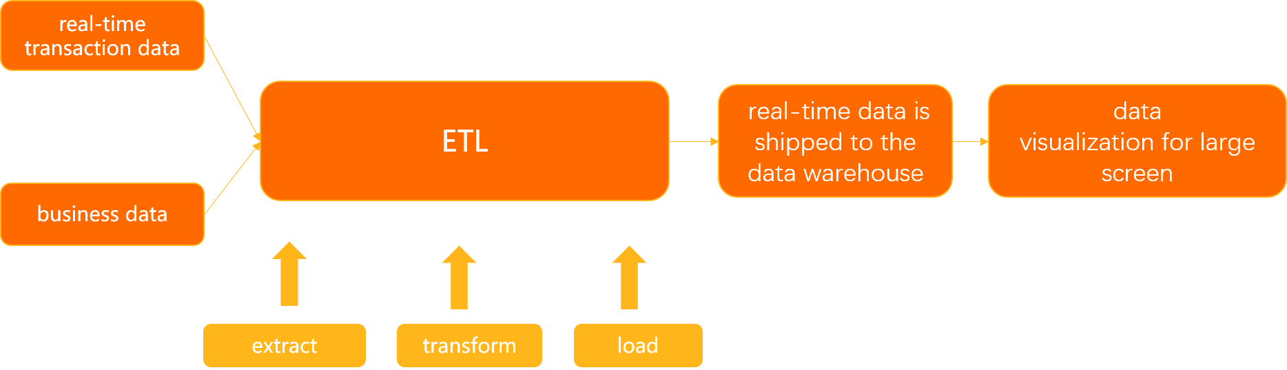
The extract, transform, and load (ETL) feature in Data Transmission Service (DTS) lets you process streaming data in real time using a visual, drag-and-drop DAG interface—no code required. This tutorial walks through a complete example: joining real-time transaction data with product reference data, filtering orders above a price threshold, and writing the results to a destination database.
Use cases
Centralized multi-source data management: Consolidate data from multiple regions or heterogeneous sources into a single database in real time.
Real-time reporting: Build reporting pipelines that reflect live business activity across dimensions such as product, customer, and time.
Real-time computing: Cleanse streaming data to extract feature values and tags for use cases like user profiling, risk control, and recommendation systems.
How it works
This example merges two data sources:
A stream table — the
test_orderstable, which receives real-time transaction events (order ID, customer ID, product ID, total price, and order date).A dimension table — the
producttable, which holds relatively static product reference data (product ID, product name, and unit price).
The ETL task joins these two tables, filters for orders where total_price > 3000.00, and writes matching rows to a destination table in real time.
A stream table is updated continuously as events arrive. A dimension table holds reference data that changes infrequently and is used to enrich stream data, similar to a lookup table.
Prerequisites
Before you begin, ensure that you have:
Access to the DTS console
An ApsaraDB RDS for MySQL instance to serve as the source (containing the stream table and dimension table)
An ApsaraDB RDS for MySQL instance to serve as the destination
Read the Prerequisites and Precautions sections of the "Configure an ETL task in DAG mode" topic before proceeding.
Prepare the source and destination tables
Create the following tables in your ApsaraDB RDS for MySQL instances.
Real-time transaction data
CREATE TABLE test_orders (
    order_id    BIGINT        NOT NULL COMMENT 'Order ID',
    user_id     BIGINT        NOT NULL COMMENT 'User ID',
    product_id  BIGINT        NOT NULL COMMENT 'Product ID',
    total_price DECIMAL(15,2) NOT NULL COMMENT 'Total price',
    order_date  TIMESTAMP     NOT NULL COMMENT 'Order date',
    PRIMARY KEY (order_id)
);
Business dimension data
CREATE TABLE product (
    product_id    BIGINT        NOT NULL COMMENT 'Product ID',
    product_name  VARCHAR(20)            COMMENT 'Product name',
    product_price DECIMAL(15,2) NOT NULL COMMENT 'Unit price'
);
Destination table
CREATE TABLE test_orders_new (
    order_id      BIGINT        NOT NULL COMMENT 'Order ID',
    user_id       BIGINT        NOT NULL COMMENT 'User ID',
    product_id    BIGINT        NOT NULL COMMENT 'Product ID',
    total_price   DECIMAL(15,2) NOT NULL COMMENT 'Total price',
    order_date    TIMESTAMP     NOT NULL COMMENT 'Order date',
    product_id_2  BIGINT        NOT NULL COMMENT 'Product ID (from product table)',
    product_name  VARCHAR(20)            COMMENT 'Product name',
    product_price DECIMAL(15,2) NOT NULL COMMENT 'Unit price',
    PRIMARY KEY (order_id)
);
The destination table usesproduct_id_2to store the product ID from theproductdimension table. This avoids a column name conflict withproduct_idfrom thetest_ordersstream table. When two joined tables share a column name, rename one of them in the destination table schema before configuring the ETL task.
Configure the ETL task
The following steps configure a data flow that joins the stream table with the dimension table, filters the results, and writes them to the destination.

Step 1: Configure the source database
Log on to the DTS console.DTS console
In the left-side navigation pane, click ETL.
In the upper-left corner of the Streaming ETL page, click
 . In the Create Data Flow dialog box, enter a name in the Data Flow Name field and set Development Method to DAG.
Click OK.
Configure the stream table:
From the left panel, drag an Input/Dimension Table MySQL node onto the canvas.
Click Input/Dimension Table MySQL-1 on the canvas.
On the Node Settings tab, configure the following parameters:
Parameter Description Data Source Name DTS generates a name automatically. Enter a descriptive name for easy identification. Region Select the region of the source database. Supported regions: China (Hangzhou), China (Shanghai), China (Qingdao), China (Beijing), China (Zhangjiakou), China (Shenzhen), China (Guangzhou), and China (Hong Kong). Instances Select the source database instance. To create a new instance, click Create Instance. See Databases supported by DMS for details. Node Type Select Stream Table. A stream table receives continuous updates and can be joined with a dimension table. Convert Format Specifies how the dynamic table is encoded when written back to a stream. Upsert Stream: INSERT and UPDATE operations are encoded as upsert messages; DELETE operations as delete messages. Requires a unique key (composite keys are supported). Append-Only Stream: Only INSERT operations are included in the output stream. Select Databases and Tables Select the databases and tables to transform. On the Output Fields tab, select the columns to include.
On the Time Attribute
Parameter Description Event Time Watermark Select the timestamp field that represents when each event was generated (for example, order_date).Latency of Event Time Watermark Enter the maximum acceptable out-of-order delay. ETL waits this long for late-arriving events before discarding them. For example, if data generated at 9:59 has not arrived by 10:00 plus the configured latency, it is discarded. Processing Time Enter a column name. ETL stores the server processing time in this column. Use processing time for temporal joins that always look up the latest version of a dimension table.
If the
 icon no longer appears on the right side of the node, the stream table is configured.
Configure the dimension table:
From the left panel, drag another Input/Dimension Table MySQL node onto the canvas.
Click Input/Dimension Table MySQL-2 on the canvas.
On the Node Settings tab, configure the following parameters:
Parameter Description Data Source Name DTS generates a name automatically. Enter a descriptive name for easy identification. Region Select the region of the source database. Instances Select the source database instance, or click Create Instance. Node Type Select Dimension Table. A dimension table holds reference data that changes infrequently and is used to enrich stream data into a wide table. Select Databases and Tables Select the databases and tables to transform. On the Output Fields tab, select the columns to include.
If the
icon no longer appears on the right side of the node, the dimension table is configured.
Step 2: Configure the Table Join component
From the Transform section in the left panel, drag a JOIN node onto the canvas.
Connect the stream table node to Table Join-1: hover over the stream table node, click the hollow circle on its right edge, and drag a connection line to Table Join-1. Repeat for the dimension table node.
Click Table Join-1 on the canvas to open its settings.
On the Node Settings tab, configure the following parameters:
Section Parameter Description Conversion Name Enter Transformation Name DTS generates a name automatically. Enter a descriptive name. JOIN Settings Left Table in JOIN Clause Select the stream table as the primary (left) table. Temporal Join Time Attribute Defines how the stream table version is matched to the dimension table. If not set, a regular join is performed. Based on Event Time Watermark: matches the version of the dimension table at the time the event was generated (use with versioned tables). Based on Processing Time: always joins the latest version of the dimension table (use with standard tables). In this example, select Based on Processing Time. Select JOIN Operation Select the join type. In this example, select Inner Join. Inner Join: returns only rows that have matching values in both tables. Left Join: returns all rows from the stream table, plus matched rows from the dimension table where available. Right Join: returns all rows from the dimension table, plus matched rows from the stream table where available. JOIN Condition + Add Condition Click + Add Condition and select the join fields. Fields on the left of the =sign belong to the left table; fields on the right belong to the right table.On the Output Fields tab, select the columns to include in the wide table.
If the
icon no longer appears on the right side of the Table Join-1 component, the join is configured.
Step 3: Configure the Table Record Filter component
From the Transform section in the left panel, drag a Table Record Filter node onto the canvas.
Connect Table Join-1 to Table Record Filter-1: hover over Table Join-1, click the hollow circle on its right edge, and drag a connection line to Table Record Filter-1.
Click Table Record Filter-1 on the canvas.
On the Node Settings tab, enter a name in the Conversion Name field.
In the WHERE Condition field, specify a filter condition using one of these methods:
Type a condition directly. For example, enter
total_price>3000.00to pass only orders with a total price above 3,000.Click fields in the Input Fields section and operators in the Operator section to build the condition visually.
If the
icon no longer appears on the right side of the component, the filter is configured.
Step 4: Configure the destination database
From the Output section in the left panel, drag a MySQL node onto the canvas.
Connect Table Record Filter-1 to Output MySQL-1: hover over Table Record Filter-1, click the hollow circle on its right edge, and drag a connection line to Output MySQL-1.
Click Output MySQL-1 on the canvas.
On the Node Settings tab, configure the following parameters:
Parameter Description Data Source Name DTS generates a name automatically. Enter a descriptive name. Region Select the region of the destination database. Supported regions: China (Hangzhou), China (Shanghai), China (Qingdao), China (Beijing), China (Zhangjiakou), China (Shenzhen), China (Guangzhou), and China (Hong Kong). Instances Select the destination database instance, or click Create Instance. Table Mapping In the Select Destination Table section, click the destination table. On the Output Fields tab, select the columns to write to the destination table.
If the
icon no longer appears on the right side of the component, the destination database is configured.
Step 5: Precheck and start the task
Click Generate Flink SQL Validation. DTS generates Flink SQL statements and runs a validation check.
After validation completes, click View ETL Validation Details to review the generated SQL and check results. Click Close when done.
If validation fails, fix the issues listed in the results and regenerate the Flink SQL.
Click Next: Save Task Settings and Precheck. The task can only start after the precheck passes. If any item fails, click View Details next to the failed item, fix the issue, and run the precheck again.
After the precheck passes, click Next: Purchase Instance.
On the Purchase Instance page, set the Instance Class and Compute Units (CUs) parameters. Read and select Data Transmission Service (Pay-as-you-go) Service Terms and Service Terms for Public Preview.
During the public preview period, each user can create up to two ETL instances at no charge.
Click Buy and Start to launch the ETL task.
Results
After the task starts, DTS continuously reads change events from test_orders, joins them with the product dimension table, applies the total_price > 3000.00 filter, and writes matching rows to test_orders_new in real time.
Figure 1. Real-time transaction data table: test_orders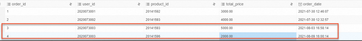
Figure 2. Destination table: test_orders_new
What's next
Configure an ETL task in DAG mode — full parameter reference for all ETL task settings
Databases supported by DMS — supported source and destination database types