The output node in a Streaming ETL DAG defines where transformed data is written. This topic explains how to add and configure an output node for a MySQL destination database in an extract, transform, and load (ETL) task.
Prerequisites
Before you begin, make sure that:
The ETL task is created in one of the following regions: China (Hangzhou), China (Shanghai), China (Qingdao), China (Beijing), China (Zhangjiakou), China (Shenzhen), China (Guangzhou), or China (Hong Kong)
The destination database is one of the supported types: MySQL, PolarDB for MySQL, Oracle, AnalyticDB for MySQL V3.0, PolarDB for PostgreSQL, PostgreSQL, Db2 for LUW, iSeries DB2 (AS/400), AnalyticDB for PostgreSQL, SQL Server, MariaDB, PolarDB-X 1.0, PolarDB for Oracle, or Tablestore
The destination database is created
The source database and transformation component are configured
Table schemas in the destination database are created manually. ETL does not support schema migration — if your ETL task joins Table A (Field 1, Field 2, Field 3) and Table B (Field 3, Field 4, Field 5) into a single output, create Table C (Field 1, Field 2, Field 3, Field 4, Field 5) in the destination database before configuring the output node
Configure the output node
The following steps use a MySQL database as the example.
Go to the Streaming ETL page.
Log on to the Data Management (DMS) console.
In the top navigation bar, move your pointer over DTS.
Choose Data integration > Streaming ETL.
In the upper-left corner of the Streaming ETL page, click
 . In the Create Data Flow dialog box, enter an ETL task name in the Data Flow Name field and set Development Method to DAG.
Click OK.
Configure the source database. For more information, see Configure a source database.
Configure the transformation component. For more information, see Configure transformation components.
On the left side of the canvas, drag the Output MySQL node to the canvas. The node is named Output MySQL-1.
Hover over the transformation component and click the dot to draw a connection line from the transformation component to the Output MySQL-1 node.
Click the Output MySQL-1 node to open its configuration panel.
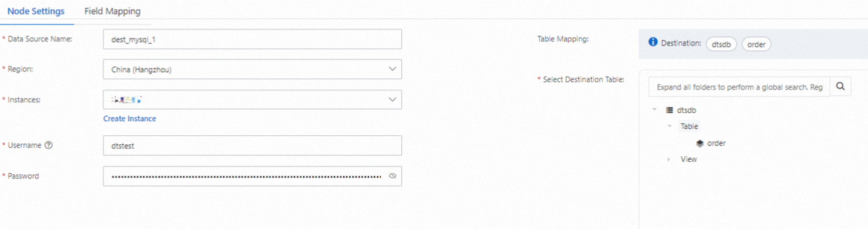
On the Node Settings tab, configure the following parameters.
Parameter
Description
Data source name
DTS auto-generates a name. Enter a descriptive name so you can identify this data source easily. The name does not need to be unique.
Region
The region where the destination database resides.
Instances
The destination database instance. Data from the ETL task is written to this instance. To create a new instance, click Create Instance below the field. For a list of supported instance types, see Databases supported by DMS.
Table mapping
The destination table where transformed data is stored.
In the Select Destination Table section, select the target table.
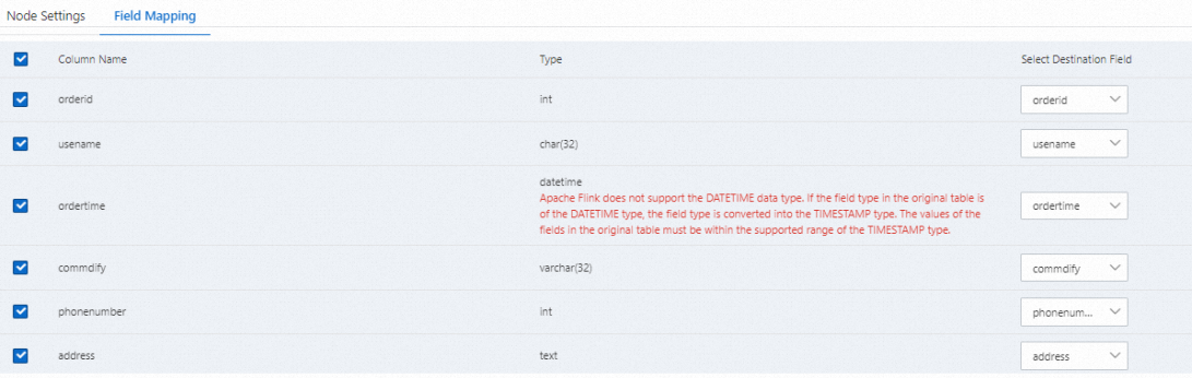
On the Field Mapping tab, select the column names based on your business requirements and configure the related parameters.
Result
After you complete the configuration, the exclamation mark icon (![]() ) disappears from the right side of the Output MySQL-1 node, indicating that the destination database is configured.
) disappears from the right side of the Output MySQL-1 node, indicating that the destination database is configured.