Data Transmission Service (DTS) requires network access to your on-premises database for data migration, synchronization, or change tracking. If the database connects to Alibaba Cloud through an IPsec-VPN tunnel, you must add the DTS server CIDR blocks to the IPsec connection so that DTS traffic can pass through the tunnel.
DTS uses multiple CIDR blocks per region. IKEv1 supports only one CIDR block in the Local Network field. Your IPsec connection must use ikev2. If your existing connection uses IKEv1, upgrade to IKEv2 before you proceed.
Prerequisites
Before you begin, ensure that you have:
An IPsec-VPN connection between your on-premises data center and an Alibaba Cloud Virtual Private Cloud (VPC). For setup instructions, see Connect a VPC to a data center in single-tunnel mode
The CIDR blocks of DTS servers in your region. For the full list, see CIDR blocks of DTS servers
Procedure
Log on to the VPC console.
In the left-side navigation pane, choose Interconnections > VPN > IPsec Connections.
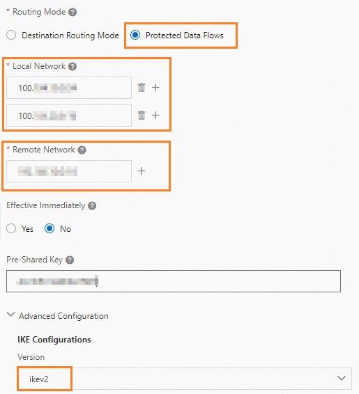
Modify the IPsec connection with the following settings:
Set Routing Mode to Protected Data Flows.
In the Local Network field, enter the CIDR blocks of all DTS servers in your region.
In the Remote Network field, enter the IP address of your data center.
In the IKE Configurations section, select ikev2 from the Version drop-down list.
Download the updated IPsec-VPN connection configuration and apply it to the gateway device in your data center. For detailed steps, see Load the IPsec-VPN connection configuration to the gateway device.
NoteWhen you update the VPN configuration on your gateway device, add only the CIDR blocks of the VPC and your data center. Do not add DTS server CIDR blocks to the gateway device configuration. For example, on an H3C firewall, enter the data center and VPC CIDR blocks in the Source IP Address and Destination IP Address fields. Leave the DTS server CIDR blocks out.
Add a static route on the gateway device in your data center. Set the destination to the CIDR blocks of DTS servers and the next hop to the IPsec-VPN tunnel interface.
Troubleshooting
If the IPsec connection fails after configuration, see Troubleshoot IPsec-VPN connections.
Next steps
After you configure the VPN route, create a DTS task to start migrating or synchronizing data:
When you configure data migration, data synchronization, or change tracking, select Express Connect, VPN Gateway, or Smart Access Gateway as the access method.
Select the VPC that is connected to your on-premises database.
Specify the on-premises database as the source or destination database.
For supported scenarios, see Data synchronization scenarios or Data migration scenarios.