This topic describes how to use a routing policy to restrict communication between Virtual Private Cloud (VPC) instances that are attached to a Cloud Enterprise Network (CEN) instance.
Prerequisites
This topic applies only to Basic Edition transit routers.
-
You have created a Cloud Enterprise Network (CEN) instance. For more information, see Create a CEN instance.
-
You have attached your VPC instances to the CEN instance. For more information, see Use a Basic Edition transit router to create a VPC connection.
Background information
By default, all network instances, such as Virtual Private Clouds (VPCs), Virtual Border Routers (VBRs), and Cloud Connect Network (CCN) instances, attached to the same Cloud Enterprise Network (CEN) instance can communicate with each other. However, in some scenarios, you may need to restrict communication between them.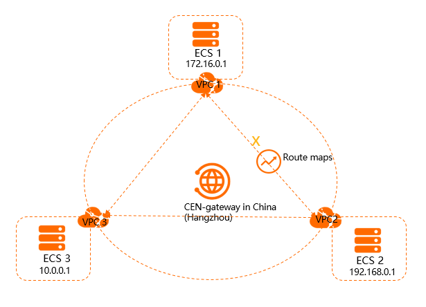
As shown in the preceding figure, VPC1, VPC2, and VPC3 are attached to the same CEN instance. By default, VPC1, VPC2, and VPC3 can communicate with each other. If you want to block traffic between VPC1 and VPC2, you can use routing policies to restrict communication between them. After you apply this configuration, communication is still allowed between VPC1 and VPC3, and between VPC2 and VPC3.
Step 1: Block traffic from VPC1 to VPC2
-
Log on to the Cloud Enterprise Network console.
-
On the CEN Instance page, find the target CEN instance and click its ID.
-
On the details page of the CEN instance, find the transit router in the target region, and click the transit router ID.
-
On the details page of the transit router, click the Route Table tab, and then click Route Maps.
-
On the Route Maps page, click Add Route Map. Configure the routing policy with the following settings and click OK.
-
Policy Priority: Enter 20. A smaller value indicates a higher priority.
-
Region: Select China (Hangzhou).
-
Policy Direction: Select RegionOut.
-
Match Condition: Set the source instance ID list to the ID of the VPC1 instance and the destination instance ID list to the ID of the VPC2 instance.
-
Policy Action: Select Deny.
After adding the policy, you can verify it. On the Network Instance Route Table tab, select the VPC1 network instance. Find the route entry for 192.168.0.0/24. The Route Type is CEN and the status is Reject. This confirms the policy is effective and blocks traffic from VPC1 to VPC2.
-
Step 2: Block traffic from VPC2 to VPC1
-
In the left-side navigation pane, click CEN Instance.
-
On the CEN Instance page, find the target CEN instance and click its ID.
-
On the details page of the CEN instance, find the transit router in the target region, and click the transit router ID.
-
On the details page of the transit router, click the Route Table tab, and then click Route Maps.
-
On the Route Maps page, click Add Route Map. Configure the routing policy with the following settings and click OK.
-
Policy Priority: Enter 50. A smaller value indicates a higher priority.
-
Region: Select China (Hangzhou).
-
Policy Direction: Select RegionOut.
-
Match Condition: Set the source instance ID list to the ID of the VPC2 instance and the destination instance ID list to the ID of the VPC1 instance.
-
Policy Action: Select Deny.
After adding the policy, you can verify it. On the Network Instance Route Table tab, select the VPC2 network instance. You will find that the status of the route entry for 172.16.0.0/24 is Reject. This confirms the policy is effective.
-
Step 3: Test network connectivity
-
Log on to the ECS1 instance in VPC1.
-
Use the ping command to ping the IP address of the ECS2 instance in VPC2 to verify that the communication is normal.
The ping test fails. This confirms that the ECS1 instance cannot access the ECS2 instance.
[root@xxx ~]# ping 192.168.0.1 PING 192.168.0.1 (192.168.0.1) 56(84) bytes of data. ^C --- 192.168.0.1 ping statistics --- 17 packets transmitted, 0 received, 100% packet loss, time 15999ms -
Log on to the ECS2 instance in VPC2.
-
Use the ping command to ping the IP address of the ECS1 instance in VPC1 to verify connectivity.
The ping test fails. This confirms that the ECS2 instance cannot access the ECS1 instance.
[root@xxx ~]# ping 172.16.0.1
PING 172.16.0.1 (172.16.0.1) 56(84) bytes of data.
^C
--- 172.16.0.1 ping statistics ---
6 packets transmitted, 0 received, 100% packet loss, time 5000ms
-
Log on to the ECS1 instance in VPC1.
-
Run the ping command to ping the IP address of the ECS3 instance in VPC3 to verify connectivity.
The ping test succeeds. This confirms that the ECS1 instance can access the ECS3 instance.
C:\Users\Administrator>ping 10.0.0.1 Pinging 10.0.0.1 with 32 bytes of data: Reply from 10.0.0.1: bytes=32 time<1ms TTL=128 Reply from 10.0.0.1: bytes=32 time<1ms TTL=128 Reply from 10.0.0.1: bytes=32 time<1ms TTL=128 Reply from 10.0.0.1: bytes=32 time<1ms TTL=128 Ping statistics for 10.0.0.1: Packets: Sent = 4, Received = 4, Lost = 0 (0% loss), Approximate round trip times in milli-seconds: Minimum = 0ms, Maximum = 0ms, Average = 0ms -
Log on to the ECS3 instance in VPC3.
-
Use the ping command to ping the IP address of the ECS1 instance in VPC1 and verify that the communication is normal.
The ping test succeeds. This confirms that the ECS3 instance can access the ECS1 instance.
C:\Users\Administrator>ping 172.16.0.1

Pinging 172.16.0.1 with 32 bytes of data:
Reply from 172.16.0.1: bytes=32 time<1ms TTL=128
Reply from 172.16.0.1: bytes=32 time<1ms TTL=128
Reply from 172.16.0.1: bytes=32 time<1ms TTL=128
Reply from 172.16.0.1: bytes=32 time<1ms TTL=128

Ping statistics for 172.16.0.1:
    Packets: Sent = 4, Received = 4, Lost = 0 (0% loss),
Approximate round trip times in milli-seconds:
    Minimum = 0ms, Maximum = 0ms, Average = 0ms
-
Log on to the ECS2 instance in VPC2.
-
Use the ping command to ping the IP address of the ECS3 instance in VPC3 to verify network connectivity.
The ping test succeeds. This confirms that the ECS2 instance can access the ECS3 instance.
-
Log on to the ECS3 instance in VPC3.
-
Run the ping command to ping the IP address of the ECS2 instance in VPC2 to verify connectivity.
The ping test succeeds. This confirms that the ECS3 instance can access the ECS2 instance.
C:\Users\Administrator>ping 192.168.0.1

Pinging 192.168.0.1 with 32 bytes of data:
Reply from 192.168.0.1: bytes=32 time<1ms TTL=128
Reply from 192.168.0.1: bytes=32 time<1ms TTL=128
Reply from 192.168.0.1: bytes=32 time<1ms TTL=128
Reply from 192.168.0.1: bytes=32 time<1ms TTL=128

Ping statistics for 192.168.0.1:
    Packets: Sent = 4, Received = 4, Lost = 0 (0% loss),
Approximate round trip times in milli-seconds:
    Minimum = 0ms, Maximum = 0ms, Average = 0ms