Cloud Enterprise Network (CEN) lets you control which virtual private clouds (VPCs) can communicate with each other within the same region. This tutorial shows how to configure CEN so that two isolated VPCs can each reach a shared VPC, while remaining isolated from each other.
Run the sample Terraform code with one click&example=201-use-case-allow-isolated-vpcs-to-access-a-shared-vpc).
Scenario
This tutorial uses a three-VPC setup in the China (Hangzhou) region:
VPC 1 and VPC 2 are isolated VPCs (for example, separate business units)
VPC 3 is the shared VPC (for example, hosting shared services such as DNS or monitoring)

Connectivity goal
| From \ To | VPC 1 | VPC 2 | VPC 3 (shared) |
|---|---|---|---|
| VPC 1 | — | No | Yes |
| VPC 2 | No | — | Yes |
| VPC 3 (shared) | Yes | Yes | — |
Network topology
Make sure the CIDR blocks of the three VPCs do not overlap.
| VPC | Primary CIDR block | vSwitch | Zone | vSwitch CIDR block | ECS IP address |
|---|---|---|---|---|---|
| VPC 1 | 192.168.0.0/16 | vSwitch 1 | Zone A | 192.168.0.0/24 | 192.168.0.224 |
| VPC 1 | 192.168.0.0/16 | vSwitch 2 | Zone B | 192.168.1.0/24 | — |
| VPC 2 | 172.16.0.0/16 | vSwitch 3 | Zone A | 172.16.0.0/24 | 172.16.0.222 |
| VPC 2 | 172.16.0.0/16 | vSwitch 4 | Zone B | 172.16.1.0/24 | — |
| VPC 3 | 10.0.0.0/16 | vSwitch 5 | Zone A | 10.0.0.0/24 | 10.0.0.112 |
| VPC 3 | 10.0.0.0/16 | vSwitch 6 | Zone B | 10.0.1.0/24 | — |
How it works
The connectivity goal requires two distinct routing behaviors: VPC 1 and VPC 2 must reach VPC 3, but must not reach each other. Because these two groups have different routing requirements, two transit router route tables are needed.
Default route table — associated with VPC 3:
Learns the system routes of all three VPCs through route propagation
Enables VPC 3 to send traffic to VPC 1 and VPC 2
Custom route table — associated with VPC 1 and VPC 2:
Contains a single static route pointing to VPC 3 (destination:
10.0.0.0/16)Forwards VPC 1 and VPC 2 traffic to VPC 3 only
Because there is no route between VPC 1 and VPC 2 in this table, packets from VPC 1 to VPC 2 (and vice versa) are dropped at the transit router — not blocked by security groups or ACLs, but simply because no matching route exists
Each VPC also needs a default route (0.0.0.0/0) pointing to the transit router, so that outbound traffic enters the CEN and is forwarded according to the route tables above.
Association and propagation rules
| VPC | Associated route table | Propagates routes to |
|---|---|---|
| VPC 3 (shared) | Default route table | Default route table |
| VPC 1 | Custom route table | Default route table |
| VPC 2 | Custom route table | Default route table |
Expected route table state
After completing the configuration, verify that the transit router route tables contain the following entries:
Default route table (associated with VPC 3):
| Destination | Next hop | Route type |
|---|---|---|
| 192.168.0.0/16 | VPC 1 attachment | Propagated |
| 172.16.0.0/16 | VPC 2 attachment | Propagated |
| 10.0.0.0/16 | VPC 3 attachment | Propagated |
Custom route table (associated with VPC 1 and VPC 2):
| Destination | Next hop | Route type |
|---|---|---|
| 10.0.0.0/16 | VPC 3 attachment | Static |
Prerequisites
Before you begin, make sure you have:
Three VPCs in the China (Hangzhou) region with non-overlapping CIDR blocks (see the topology table above)
Two vSwitches in different zones for each VPC
ECS instances deployed in each VPC for connectivity testing
Security group rules that allow ICMP traffic between the ECS instances
Console
Step 1: Create a CEN instance
Log on to the CEN console.
On the Instances page, click Create CEN Instance.
In the Create CEN Instance dialog box, set Name and Description, then click OK.
Step 2: Attach VPCs to the CEN instance
Attach all three VPCs to the CEN instance. The key difference is which advanced settings to enable for each VPC.
On the Instances page, click the ID of your CEN instance.
On the Basic Information tab, click the
 icon under VPC.
On the Connection with Peer Network Instance page, set the following parameters: For vSwitch selection: if the Enterprise Edition transit router supports multiple zones, select one vSwitch per zone. Two vSwitches in different zones enable zone-disaster recovery and reduce network latency.
Parameter Value Network Type Virtual Private Cloud (VPC) Region China (Hangzhou) Transit Router The system automatically creates a transit router in the selected region Resource Owner UID Current Account Billing method Pay-As-You-Go Attachment Name Enter a name for the connection Network Instance Select the VPC to attach vSwitch Select vSwitches in at least two different zones Under Advanced Settings, enable the following features based on the VPC being attached: What these settings do:
Associate with Default Route Table of Transit Router — the VPC attachment is associated with the default route table, so the transit router forwards the VPC's traffic using that table.
Propagate System Routes to Default Route Table of Transit Router — the system routes of the VPC are advertised to the default route table, making the VPC reachable from other attached network instances.
ImportantThe Automatically Creates Route That Points to Transit Router and Adds to All Route Tables of Current VPC feature adds three private routes (
10.0.0.0/8,172.16.0.0/12,192.168.0.0/16) to the VPC route tables. If any of these routes already exist in the VPC, the automatic creation fails and you must add the route manually. Click Check Route under Advanced Settings to verify.VPC Associate with default route table Propagate system routes to default route table VPC 3 (shared) Yes Yes VPC 1 No Yes VPC 2 No Yes Click OK. After attaching VPC 3, click Create More Connections and repeat for VPC 1 and VPC 2.
After creating all three VPC connections, click Return to the List.
Step 3: Associate VPC 1 and VPC 2 with a custom route table
On the CEN instance details page, click the ID of the transit router.
On the transit router details page, click the Route Table tab.
In the left-side section, click Create Route Table.
In the Create Route Table dialog box, set the following parameters and click OK:
Parameter Value Route Table Name Enter a name for the route table Route Table Description Enter a description for the route table Multi-region ECMP Routing Keep the default value Click View Route Table Details to return to the Route Table tab.
Select the custom route table you just created, click the Route Table Association tab, then click Create Association.
In the Add Association dialog box, select the VPC 1 connection and click OK. Repeat to associate VPC 2. After this step, VPC 1 and VPC 2 forward traffic by querying the custom route table.
Click the Route Entry tab, then click Add Route Entry.
In the Add Route Entry dialog box, set the following parameters and click OK:
Parameter Value Destination CIDR Block 10.0.0.0/16 Blackhole Route No Next Hop VPC 3 (select the VPC 3 attachment)
Step 4: Add a default route to each VPC
Add a default route (0.0.0.0/0) pointing to the transit router in the route tables of VPC 1, VPC 2, and VPC 3.
Log on to the VPC console.
In the left-side navigation pane, click Route Tables.
In the top navigation bar, select the China (Hangzhou) region.
Click the ID of the route table for VPC 3.
On the Custom Route tab, click Route Entry, then click Add Route Entry.
Set the following parameters and click OK: For more information, see Use custom route tables to manage network traffic.
Parameter Value Destination CIDR Block 0.0.0.0/0 Next Hop Type Transit Router Transit Router Select the VPC 3 connection Repeat steps 4–6 for VPC 1 and VPC 2, selecting their respective VPC connections as the next hop.
Verify the route tables
After completing the configuration, confirm that the route tables match the expected state shown in the Expected route table state section above.
View VPC routes:
On the transit router details page, click Network Routes.
From the Network Instance drop-down list, select VPC 1, VPC 2, or VPC 3 to view its routes.
Figure 1. Routes of VPC 1

Figure 2. Routes of VPC 2

Figure 3. Routes of VPC 3

View transit router route tables:
On the transit router details page, click the Route Table tab.
Select the default route table or the custom route table to view its routes.
Figure 4. Default route table

Figure 5. Custom route table

Step 5: Test network connectivity
Before testing, make sure the security group rules of VPC 1, VPC 2, and VPC 3 allow ICMP traffic between ECS instances. See View security group rules.
Log on to the ECS instance in VPC 1. See Overview of ECS remote connection methods.
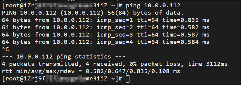
Ping the ECS instance in VPC 3 to test VPC 1 to VPC 3 connectivity:
ping 10.0.0.112Expected result: packets reach VPC 3.
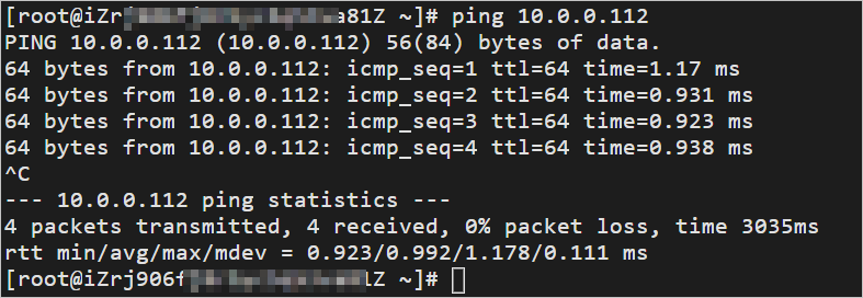
Log on to the ECS instance in VPC 2 and ping the ECS instance in VPC 3 to test VPC 2 to VPC 3 connectivity:
ping 10.0.0.112Expected result: packets reach VPC 3.
Log on to the ECS instance in VPC 1 and ping the ECS instance in VPC 2 to confirm isolation:
ping 172.16.0.222Expected result: packets do not reach VPC 2, confirming that VPC 1 and VPC 2 are isolated. The transit router drops these packets because the custom route table has no route for
172.16.0.0/16.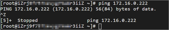
Terraform
Use TerraformInstall Terraform to provision the entire environment with code. The steps below use Terraform v1.9.8 on a Linux host. Before starting, complete authentication.Authentication
Some resources in this example incur costs. Release them when no longer needed.
Step 1: Create resources
Create a working directory and navigate to it:
mkdir tf-CenSharedVpc && cd tf-CenSharedVpcCreate the
main.tffile:touch main.tfOpen
main.tf, paste the following configuration, and save:variable "pname" { description = "The prefix name for the resources" type = string default = "tf-CenSharedVpc" } variable "default_region" { description = "Default region" type = string default = "cn-hangzhou" } variable "az_list" { description = "List of availability zones to use" type = list(string) default = ["cn-hangzhou-j", "cn-hangzhou-k"] } variable "vpc_cidr_list" { description = "List of VPC CIDR block" type = list(string) default = ["192.168.0.0/16", "172.16.0.0/12", "10.0.0.0/16"] } variable "vsw_cidr_list" { description = "List of VSW CIDR block" type = list(string) default = [ "192.168.0.0/24", "192.168.1.0/24", "172.16.0.0/24", "172.16.1.0/24", "10.0.0.0/24", "10.0.1.0/24" ] } variable "ecs_ip_list" { description = "List of ECS ip" type = list(string) default = ["192.168.0.124", "172.16.0.222", "10.0.0.112"] } provider "alicloud" { region = var.default_region } # --- 3vpc 6vsw 3ecs resource "alicloud_vpc" "vpc" { count = length(var.vpc_cidr_list) vpc_name = "${var.pname}-vpc${count.index + 1}" cidr_block = var.vpc_cidr_list[count.index] } resource "alicloud_vswitch" "vsw" { count = length(var.vsw_cidr_list) vpc_id = alicloud_vpc.vpc[floor(count.index / length(var.az_list))].id cidr_block = var.vsw_cidr_list[count.index] zone_id = var.az_list[count.index % length(var.az_list)] vswitch_name = "${var.pname}-vsw${count.index + 1}" } resource "alicloud_instance" "ecs" { count = length(var.vpc_cidr_list) instance_name = "${var.pname}-ecs${count.index + 1}" instance_type = "ecs.e-c1m1.large" security_groups = [alicloud_security_group.sg[count.index].id] vswitch_id = alicloud_vswitch.vsw[count.index * length(var.az_list)].id image_id = "aliyun_3_x64_20G_qboot_alibase_20230727.vhd" system_disk_category = "cloud_essd" private_ip = var.ecs_ip_list[count.index] instance_charge_type = "PostPaid" } # --- 3 sg resource "alicloud_security_group" "sg" { count = length(var.vpc_cidr_list) name = "${var.pname}-${count.index + 1}" vpc_id = alicloud_vpc.vpc[count.index].id } resource "alicloud_security_group_rule" "allow_inbound_ssh" { count = length(var.vpc_cidr_list) type = "ingress" ip_protocol = "tcp" nic_type = "intranet" policy = "accept" port_range = "22/22" priority = 1 security_group_id = alicloud_security_group.sg[count.index].id cidr_ip = "0.0.0.0/0" } resource "alicloud_security_group_rule" "allow_inbound_icmp" { count = length(var.vpc_cidr_list) type = "ingress" ip_protocol = "icmp" nic_type = "intranet" policy = "accept" port_range = "-1/-1" priority = 1 security_group_id = alicloud_security_group.sg[count.index].id cidr_ip = "0.0.0.0/0" } # --- cen and tr resource "alicloud_cen_instance" "cen" { cen_instance_name = "${var.pname}-cen1" } resource "alicloud_cen_transit_router" "tr" { transit_router_name = "${var.pname}-tr" cen_id = alicloud_cen_instance.cen.id } data "alicloud_cen_transit_router_route_tables" "tr" { # get tr sys table transit_router_id = alicloud_cen_transit_router.tr.transit_router_id transit_router_route_table_type = "System" } # 3 attach resource "alicloud_cen_transit_router_vpc_attachment" "attach" { count = length(var.vpc_cidr_list) cen_id = alicloud_cen_instance.cen.id transit_router_id = alicloud_cen_transit_router.tr.transit_router_id vpc_id = alicloud_vpc.vpc[count.index].id zone_mappings { zone_id = var.az_list[0] vswitch_id = alicloud_vswitch.vsw[count.index * length(var.az_list)].id } zone_mappings { zone_id = var.az_list[1] vswitch_id = alicloud_vswitch.vsw[count.index * length(var.az_list) + 1].id } transit_router_vpc_attachment_name = "attach${count.index + 1}" } # 3 propa resource "alicloud_cen_transit_router_route_table_propagation" "propa" { count = length(var.vpc_cidr_list) transit_router_route_table_id = data.alicloud_cen_transit_router_route_tables.tr.tables[0].id transit_router_attachment_id = alicloud_cen_transit_router_vpc_attachment.attach[count.index].transit_router_attachment_id } # 1 custom_table resource "alicloud_cen_transit_router_route_table" "custom_table" { # create tr custom_table transit_router_id = alicloud_cen_transit_router.tr.transit_router_id transit_router_route_table_name = "custom_table" } resource "alicloud_cen_transit_router_route_entry" "tr_entry" { transit_router_route_table_id = alicloud_cen_transit_router_route_table.custom_table.transit_router_route_table_id transit_router_route_entry_destination_cidr_block = "10.0.0.0/16" transit_router_route_entry_next_hop_type = "Attachment" transit_router_route_entry_name = "entry1_name" transit_router_route_entry_description = "entry1_desc" transit_router_route_entry_next_hop_id = alicloud_cen_transit_router_vpc_attachment.attach[2].transit_router_attachment_id } # associate attach1\2 custom_table resource "alicloud_cen_transit_router_route_table_association" "ass1" { transit_router_route_table_id = alicloud_cen_transit_router_route_table.custom_table.transit_router_route_table_id transit_router_attachment_id = alicloud_cen_transit_router_vpc_attachment.attach[0].transit_router_attachment_id } resource "alicloud_cen_transit_router_route_table_association" "ass2" { transit_router_route_table_id = alicloud_cen_transit_router_route_table.custom_table.transit_router_route_table_id transit_router_attachment_id = alicloud_cen_transit_router_vpc_attachment.attach[1].transit_router_attachment_id } # ass attach3 sys_table resource "alicloud_cen_transit_router_route_table_association" "ass3" { transit_router_route_table_id = data.alicloud_cen_transit_router_route_tables.tr.tables[0].id transit_router_attachment_id = alicloud_cen_transit_router_vpc_attachment.attach[2].transit_router_attachment_id } # vpc entry resource "alicloud_route_entry" "vpc_entry" { count = length(var.vpc_cidr_list) route_table_id = alicloud_vpc.vpc[count.index].route_table_id destination_cidrblock = "0.0.0.0/0" nexthop_type = "Attachment" nexthop_id = alicloud_cen_transit_router_vpc_attachment.attach[count.index].transit_router_attachment_id } output "ecs1_login_address" { value = "https://ecs-workbench.aliyun.com/?from=EcsConsole&instanceType=ecs®ionId=${var.default_region}&instanceId=${alicloud_instance.ecs[0].id}" } output "ecs2_login_address" { value = "https://ecs-workbench.aliyun.com/?from=EcsConsole&instanceType=ecs®ionId=${var.default_region}&instanceId=${alicloud_instance.ecs[1].id}" } output "ecs3_login_address" { value = "https://ecs-workbench.aliyun.com/?from=EcsConsole&instanceType=ecs®ionId=${var.default_region}&instanceId=${alicloud_instance.ecs[2].id}" }Initialize the working directory:
terraform initApply the configuration. Terraform displays a preview of the resources to be created. Enter
yesto confirm:terraform apply
Step 2: Test the connectivity
Log on to ECS 1 in VPC 1 (instance name:
tf-CenSharedVpc-ecs1). The login address for ECS 1 is in the Terraform output. Copy it into a browser and select Temporary SSH Key-based authentication.
Ping the ECS instance in VPC 3 to test VPC 1 to VPC 3 connectivity:
ping 10.0.0.112Expected result: packets reach VPC 3.
Log on to ECS 2 in VPC 2 (instance name:
tf-CenSharedVpc-ecs2). Ping the ECS instance in VPC 3 to test VPC 2 to VPC 3 connectivity:ping 10.0.0.112Expected result: packets reach VPC 3.
Log on to ECS 1 in VPC 1 (instance name:
tf-CenSharedVpc-ecs1). Ping the ECS instance in VPC 2 to confirm isolation:ping 172.16.0.222Expected result: packets do not reach VPC 2. The transit router drops them because the custom route table has no route for
172.16.0.0/16.
Step 3: Release resources
When verification is complete, destroy all resources to stop billing:
terraform destroy --auto-approveWhat's next
To enable IPv6 traffic between VPCs, configure route synchronization for the VPC connections, or manually add IPv6 route entries pointing to each VPC connection.
To manage VPC route tables programmatically, see Use custom route tables to manage network traffic.