Traffic lanes in permissive mode allow you to isolate application versions. Traffic is routed to different lanes based on request routing headers and end-to-end (E2E) pass-through request headers. When services in a lane call each other, if the service to be called does not exist in the lane, requests are forwarded to the same service in the baseline lane. This feature ensures the integrity of call chains and simplifies traffic management. This topic describes how to use traffic lanes in permissive mode in scenarios where request routing headers are the same as E2E pass-through request headers.
Before you get started, make sure that you have read and understood the Use traffic lanes in permissive mode to manage end-to-end traffic topic and related content.
Scenario description
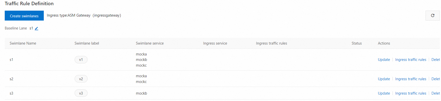
In this example, three lanes (s1, s2, and s3) are created and represent three versions of the mocka, mockb, and mockc services. s1 is the baseline lane and contains all three services of v1. s2 contains only the mocka and mockc services of v2. s3 contains only the mockb service of v3. In this example, both the E2E pass-through request header and the request routing header are specified as my-trace-id.
Step 1: Create a lane group and corresponding lanes
Create a lane group.
Log on to the ASM console. In the left-side navigation pane, choose .
On the Mesh Management page, click the name of the ASM instance. In the left-side navigation pane, choose .
On the Traffic Lane page, click Create Swimlane Group. In the Create Swimlane Group panel, set the parameters and click OK.
Parameter
Description
Name of swim lane group
For this example, enter test.
Entrance gateway
Select ingressgateway.
Lane Mode
Select Permissive Mode.
Pass-through Mode of Trace Context
Select Pass Through Custom Header.
E2E Pass-through Request Header
Enter my-trace-id.
Lane Services
Select the desired ACK cluster from the Kubernetes Clusters drop-down list and select default from the Namespace drop-down list. Then, select mocka, mockb, and mockc in the service list, and click the
 icon to add the services to the selected section.
Create s1, s2, and s3 lanes and bind the s1 lane to version 1 (v1) of the sample services, the s2 lane to version 2 (v2) of the sample services, and the s3 lane to version 3 (v3) of the sample services.
In the Traffic Rule Definition section of the Traffic Lane page, click Create swimlanes.
In the Create swimlanes dialog box, set the parameters and click OK.
Parameter
Description
Swimlane Name
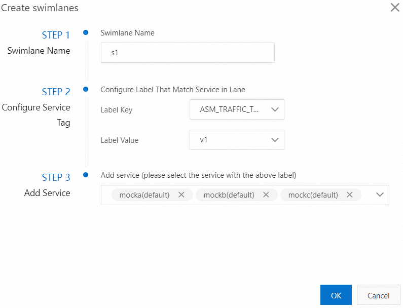
Name the three lanes as s1, s2, and s3 respectively.
Configure Service Tag
Label Key: Select ASM_TRAFFIC_TAG.
Label Value: Select v1 for the s1 lane, v2 for the s2 lane, and v3 for the s3 lane.
Add Service
For the s1 lane, select mocka(default), mockb(default), and mockc(default).
For the s2 lane, select mocka(default) and mockc(default).
For the s3 lane, select mockb(default).
The following figure shows the configurations of the s1 lane.
After the three lanes are created, you can view them in the Traffic Rule Definition section, as shown in the following figure. By default, the first lane you create in a lane group is set as the baseline lane. However, you can change the baseline lane. When traffic is destined for services that do not exist in the other lanes, requests are forwarded to the baseline lane according to the fallback mechanism. For more information about how to change the baseline lane, see Change the baseline lane in permissive mode.
A destination rule and a virtual service are automatically generated for each service in the lanes. You can choose or VirtualService in the left-side navigation pane to view the destination rule or virtual service. For example, the following destination rule and virtual service are automatically created for the mocka service.
Create a traffic routing rule for each lane.
In the Traffic Rule Definition section of the Traffic Lane page, find the lane for which you want to create a traffic routing rule, and click Ingress traffic rules in the Actions column.
In the Add drainage rule dialog box, set the parameters and click OK.
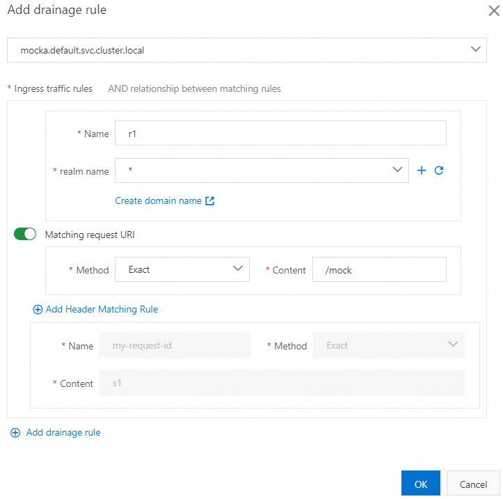
This example assumes that the inbound request path of all services in the lanes is
/mock, and the same traffic routing rule is configured for each lane.Parameter
Description
Ingress service
For this example, select mocka.default.svc.cluster.local.
Ingress traffic rules
For this example, set the Name parameter to r1, r2, and r3 respectively for the three lanes. Set the realm name parameter to *.
Matching request URI
For this example, set the Method parameter to Exact and the Content parameter to /mock.
The following figure shows the configurations of the traffic routing rule for the s1 lane.
After traffic routing rules are created, you can view them in the Traffic Rule Definition section, as shown in the following figure:

After a traffic routing rule is created, a virtual service is automatically generated for the lane. For example, the following virtual service is generated for the s2 lane.
Step 2: Verify that the E2E canary release feature takes effect
Obtain the public IP address of the ASM ingress gateway. For more information, see Step 2: Obtain the IP address of the ASM ingress gateway in Step 2: Obtain the IP address of the ASM ingress gateway.
Run the following command to configure an environment variable.
xxx.xxx.xxx.xxxis the IP address obtained in substep 1.export ASM_GATEWAY_IP=xxx.xxx.xxx.xxxVerify that the E2E canary release feature takes effect.
Run the following command to access services in the s1 lane.
In the command, the value of
my-trace-idiss1, which is the name of the s1 lane that you configured when you created the s1 lane in substep 2 of Step 1.for i in {1..100}; do curl -H'my-trace-id: s1' http://${ASM_GATEWAY_IP}/mock ; echo ''; sleep 1; done;Expected output:
-> mocka(version: v1, ip: 172.17.0.54)-> mockb(version: v1, ip: 172.17.0.129)-> mockc(version: v1, ip: 172.17.0.130)The output indicates that traffic specified by the HTTP header
my-trace-id: s1flows to the relevant services in the s1 lane. This meets expectations.Run the following command to access services in the s2 lane.
In the command, the value of
my-trace-idiss2, which is the name of the s2 lane that you configured when you created the s2 lane in substep 2 of Step 1.for i in {1..100}; do curl -H'my-trace-id: s2' http://${ASM_GATEWAY_IP}/mock ; echo ''; sleep 1; done;Expected output:
mocka(version: v2, ip: 192.168.1.101)-> mockb(version: v1, ip: 192.168.1.100)-> mockc(version: v2, ip: 192.168.1.116)The output indicates that traffic specified by the HTTP header
my-trace-id: s2flows to the relevant services in the s2 lane. This meets expectations. When traffic is destined for the mockb service that does not exist in the s2 lane, the traffic is forwarded to the mockb service in the s1 baseline lane according to the fallback mechanism. Then, the traffic is sent to the mockc service in the s2 lane as expected.Run the following command to access the service in the s3 lane.
In the command, the value of
my-trace-idiss3, which is the name of the s3 lane that you configured when you created the s3 lane in substep 2 of Step 1.for i in {1..100}; do curl -H'my-trace-id: s3' http://${ASM_GATEWAY_IP}/mock ; echo ''; sleep 1; done;Expected output:
mocka(version: v1, ip: 192.168.1.103)-> mockb(version: v3, ip: 192.168.1.120)-> mockc(version: v1, ip: 192.168.1.105)The output indicates that traffic specified by the HTTP header
my-trace-id: s3flows to the relevant service in the s3 lane. This meets expectations. When traffic is destined for the mocka and mockc services that do not exist in the s3 lane, the traffic is forwarded to the mocka and mockc services in the s1 baseline lane according to the fallback mechanism.