Multi-cluster gateways in ACK One use MSE Ingresses as global Ingresses to centrally manage inbound traffic for applications deployed across multiple clusters. This topic shows how to create a multi-cluster gateway, attach clusters to it, and configure traffic routing policies including load balancing, cluster-specific routing, header-based routing, weight-based routing, and automatic failover.
Fees are charged when you use multi-cluster gateways. For billing details, see Billing overview of common instances.
Background
Standard Kubernetes Ingresses are cluster-scoped and cannot route traffic across clusters. Multi-cluster gateways solve this by using MSE Ingresses as global Ingresses, giving you:
-
Active zone-redundancy — the gateway deploys across zones by default for high availability
-
Cross-cluster load balancing — traffic is distributed proportionally to pod counts across clusters
-
Header-based traffic routing — route specific requests to specific clusters using request headers
-
Weight-based traffic distribution — send a configurable percentage of traffic to a target cluster for canary releases
-
Automatic cross-cluster failover — if a Service in one cluster goes down, traffic fails over to healthy clusters automatically, with no configuration required
MSE references
-
MseIngressConfig is a CustomResourceDefinition (CRD) provided by the MSE Ingress Controller. It manages the lifecycle of MSE cloud-native gateways and controls Ingress listening and global settings. See Configure an MseIngressConfig.
-
MSE Ingresses support the core annotations of NGINX Ingress and add annotations that extend beyond NGINX Ingress capabilities. See Annotations supported by MSE Ingress gateways.
Prerequisites
Before you begin, ensure that you have:
-
Created a namespace on the ACK One Fleet instance that matches the namespace of applications in the associated clusters
Step 1: Create a multi-cluster gateway
Create a multi-cluster gateway on the Fleet instance. By default, the gateway deploys across zones for high availability.
Use the console
-
Log on to the ACK One console. In the left-side navigation pane, choose Fleet > Multi-cluster Gateways.
-
In the upper-right corner of the Multi-cluster Gateway page, click Create Gateway.
-
In the panel that appears, edit the YAML file to match your requirements, then click Create.
Use the CLI
-
Get the vSwitch ID of the Fleet instance. Run the following command:
aliyun adcp DescribeHubClusterDetails --ClusterId <YOUR_FLEET_CLUSTERID>Record the vSwitch ID from the
VSwitchesfield in the output. -
Create a file named
mseingressconfig.yamlwith the following content. Replace${vsw-id1}with the vSwitch ID you recorded. To attach associated clusters at creation time, uncomment and populate theannotationsfield.apiVersion: mse.alibabacloud.com/v1alpha1 kind: MseIngressConfig metadata: name: ackone-gateway # Attach associated clusters to the MSE gateway. #annotations: # mse.alibabacloud.com/remote-clusters: ${cluster1},${cluster2} spec: common: instance: replicas: 3 spec: 2c4g network: # Configure a public-facing or internal SLB instance. Defaults to public if not specified. #publicSLBSpec: slb.s2.small #privateSLBSpec: slb.s2.small vSwitches: - ${vsw-id1} ingress: local: ingressClass: mse name: mse-ingress -
Apply the configuration to create the gateway:
kubectl apply -f mseingressconfig.yaml -
Verify that the gateway was created successfully:
Status Description Pending The gateway is being created. This typically takes about 3 minutes. Running The gateway is created and running, but not yet listening. Listening The gateway is running and listening for MSE Ingresses. Failed The gateway is invalid. Check the messagefield inStatusto troubleshoot.kubectl get mseingressconfig ackone-gatewayExpected output:
NAME             STATUS      AGE
ackone-gateway   Listening   3m15s
A
Listeningstatus means the cloud-native gateway is running and listening for Ingresses withingressClassName: mse. The gateway moves through the following states:
Step 2: Attach associated clusters
Add associated clusters to the multi-cluster gateway so it can route traffic to their Services.
Use the console
-
Log on to the ACK One console. In the left-side navigation pane, choose Fleet > Multi-cluster Gateways.
-
From the Select a gateway drop-down list, select the target gateway, then click Modify in the upper-right corner.
-
In the ModifyGateway panel, add the following annotation to the
metadataobject in the YAML file. Replace${cluster1-id}and${cluster2-id}with the IDs of the clusters to attach, separated by commas. Then click Update.annotations: mse.alibabacloud.com/remote-clusters: ${cluster1-id},${cluster2-id}If you did not add clusters when creating the gateway, the
annotationsfield is absent — add it to themetadataobject manually.
Use the CLI
-
Edit the
mseingressconfigon the Fleet instance to update the annotation. Replace${cluster1-id}and${cluster2-id}with actual cluster IDs, separated by commas.annotations: mse.alibabacloud.com/remote-clusters: ${cluster1-id},${cluster2-id} -
Verify that the clusters are attached:
kubectl get mseingressconfig ackone-gateway -ojsonpath="{.status.remoteClusters}"Expected output:
[{"clusterId":"c7fb82****"},{"clusterId":"cd3007****"}]The output lists the attached cluster IDs with no
Failedentries, confirming the clusters are successfully attached.
Step 3: Deploy a sample application with GitOps
Use GitOps to deploy the web-demo sample application to the associated clusters. For setup instructions, see Getting started with GitOps.
-
Create one GitOps application per associated cluster. In this example, the applications are named
web-demo-cluster1andweb-demo-cluster2. -
Set the following Source fields:
Field Value Repository URL https://github.com/AliyunContainerService/gitops-demo.gitRevision HEADPath manifests/helm/web-demo -
Set Destination to the associated cluster and set
namespacetoweb-demo. -
In Helm Values Files, set the
envNamevariable tocluster1for the first application andcluster2The resulting Deployment and Service for cluster1 look like this:
Step 4: Configure traffic routing with MSE Ingresses
Set ingressClassName: mse on an Ingress to make it an MSE Ingress and enable multi-cluster traffic routing. MSE Ingresses support all core NGINX Ingress annotations and add MSE-specific annotations for advanced traffic governance.
Ingress objects and Service objects must be in the same namespace.
The following examples cover five common routing scenarios.
Example 1: Distribute traffic evenly across clusters
This example routes traffic proportionally to pod counts across both clusters. With one pod per cluster (1:1 ratio), traffic splits equally.
-
Create a file named
ingress-demo.yaml:apiVersion: networking.k8s.io/v1 kind: Ingress metadata: name: web-demo namespace: web-demo spec: ingressClassName: mse rules: - host: example.com http: paths: - path: /svc1 pathType: Exact backend: service: name: service1 port: number: 80 -
Apply the Ingress to the Fleet instance:
kubectl apply -f ingress-demo.yaml -
Get the public IP address of the multi-cluster gateway:
kubectl get ingress web-demo -nargocd -ojsonpath="{.status.loadBalancer}" -
Test traffic routing. Replace
XX.XX.XX.XXwith the IP address from the previous step.for i in {1..50}; do curl -H "host: example.com" XX.XX.XX.XX/svc1; sleep 1; doneExpected output:
This is env cluster1 !
Config file is
This is env cluster1 !
Config file is
This is env cluster1 !
Config file is
This is env cluster1 !
Config file is
This is env cluster2 !
Config file is
This is env cluster1 !
Config file is
...
Traffic is distributed to both clusters in proportion to their pod counts (1:1 in this example). To shift the ratio, scale the Deployment in either cluster.
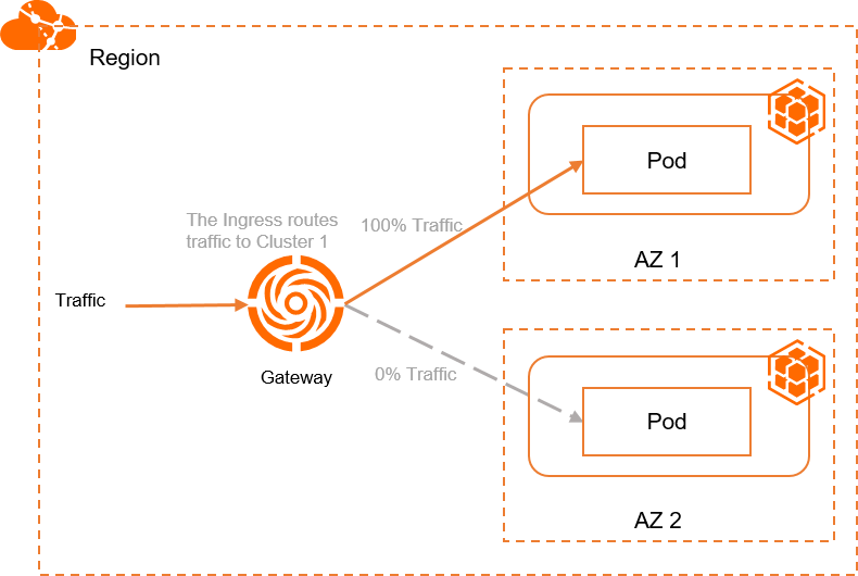
Example 2: Route all traffic to a single cluster
This example pins all traffic to Cluster 1 using the mse.ingress.kubernetes.io/service-subset and mse.ingress.kubernetes.io/subset-labels annotations.
-
Create a file named
ingress-demo-cluster-one.yaml. Replace${cluster1-id}with the ID of the first associated cluster.Annotation Description mse.ingress.kubernetes.io/service-subsetName of the Service subset. Use a name that identifies the cluster. mse.ingress.kubernetes.io/subset-labelsID of the associated cluster to route traffic to. apiVersion: networking.k8s.io/v1 kind: Ingress metadata: annotations: mse.ingress.kubernetes.io/service-subset: cluster-demo-1 mse.ingress.kubernetes.io/subset-labels: | topology.istio.io/cluster ${cluster1-id} name: web-demo-cluster-one namespace: web-demo spec: ingressClassName: mse rules: - host: example.com http: paths: - path: /service1 pathType: Exact backend: service: name: service1 port: number: 80Annotation reference: For the full list of supported annotations, see Annotations supported by MSE Ingress gateways.
-
Apply the Ingress:
kubectl apply -f ingress-demo-cluster-one.yaml -
Get the public IP address:
kubectl get ingress web-demo -nargocd -ojsonpath="{.status.loadBalancer}" -
Test traffic routing. Replace
XX.XX.XX.XXwith the gateway IP.for i in {1..50}; do curl -H "host: example.com" XX.XX.XX.XX/service1; sleep 1; doneExpected output:
This is env cluster1 !
Config file is
This is env cluster1 !
Config file is
This is env cluster1 !
Config file is
...
All requests are served by Cluster 1.
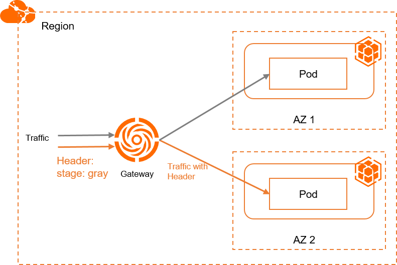
Example 3: Route canary traffic by request header
This example routes requests with the stage: gray header to Cluster 2 and all other traffic to the other cluster (via the Ingress from Example 1 or Example 2).
Header-based routing requires two Ingresses with the same host and path — one with the canary annotation and header match policy, and one without. The non-canary Ingress handles all unmatched traffic. Create the Ingress from Example 1 or Example 2 before applying this example.
-
Create a file named
ingress-demo-header.yaml:apiVersion: networking.k8s.io/v1 kind: Ingress metadata: annotations: mse.ingress.kubernetes.io/service-subset: cluster-demo-2 mse.ingress.kubernetes.io/subset-labels: | topology.istio.io/cluster c15d48ca9d1fd43f9bbb89c56a474843c nginx.ingress.kubernetes.io/canary: "true" nginx.ingress.kubernetes.io/canary-by-header: "stage" nginx.ingress.kubernetes.io/canary-by-header-value: "gray" name: web-demo-cluster-second namespace: web-demo spec: ingressClassName: mse rules: - host: example.com http: paths: - path: /service1 pathType: Exact backend: service: name: service1 port: number: 80 -
Apply the Ingress:
kubectl apply -f ingress-demo-header.yaml -
Get the public IP address:
kubectl get ingress web-demo -nargocd -ojsonpath="{.status.loadBalancer}" -
Test header-based routing. Replace
XX.XX.XX.XXwith the gateway IP.for i in {1..50}; do curl -H "host: example.com" -H "stage: gray" xx.xx.xx.xx/service1; sleep 1; doneExpected output:
This is env cluster2 !
Config file is
This is env cluster2 !
Config file is
This is env cluster2 !
Config file is
...
The output indicates that traffic with the
stage: grayheader is distributed to Cluster 2.
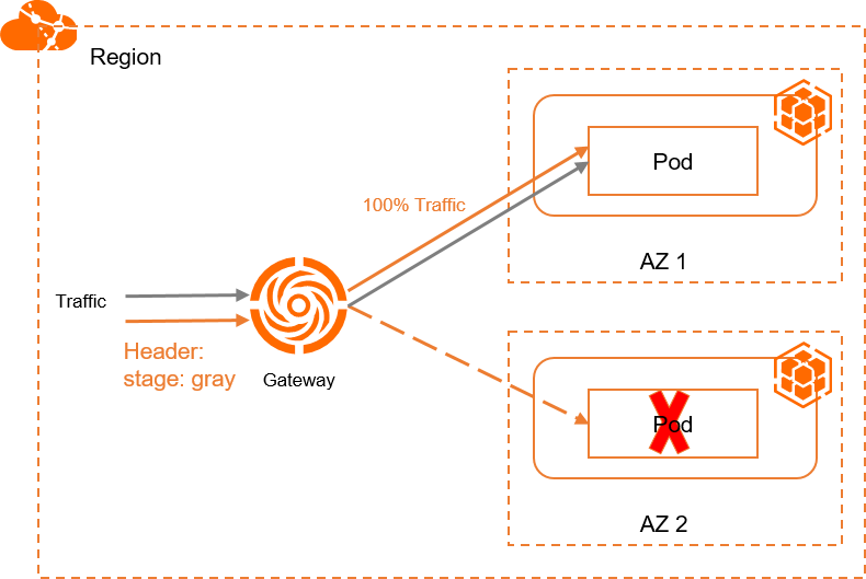
Example 4: Automatic cross-cluster failover
Multi-cluster gateways automatically fail over traffic when a Service in one cluster becomes unavailable. No additional configuration is required.
This example demonstrates failover using the setup from Example 3. Requests with stage: gray normally go to Cluster 2. When the Service in Cluster 2 is down or deleted, traffic automatically fails over to Cluster 1.
-
Get the public IP address of the gateway:
kubectl get ingress web-demo -nargocd -ojsonpath="{.status.loadBalancer}" -
Send requests with the
stage: grayheader. ReplaceXX.XX.XX.XXwith the gateway IP.for i in {1..50}; do curl -H "host: example.com" -H "stage: gray" XX.XX.XX.XX/service1; sleep 1; doneExpected output:
This is env cluster1 !
Config file is
This is env cluster1 !
Config file is
This is env cluster1 !
Config file is
...
The output indicates that traffic is automatically failed over to Cluster 1.
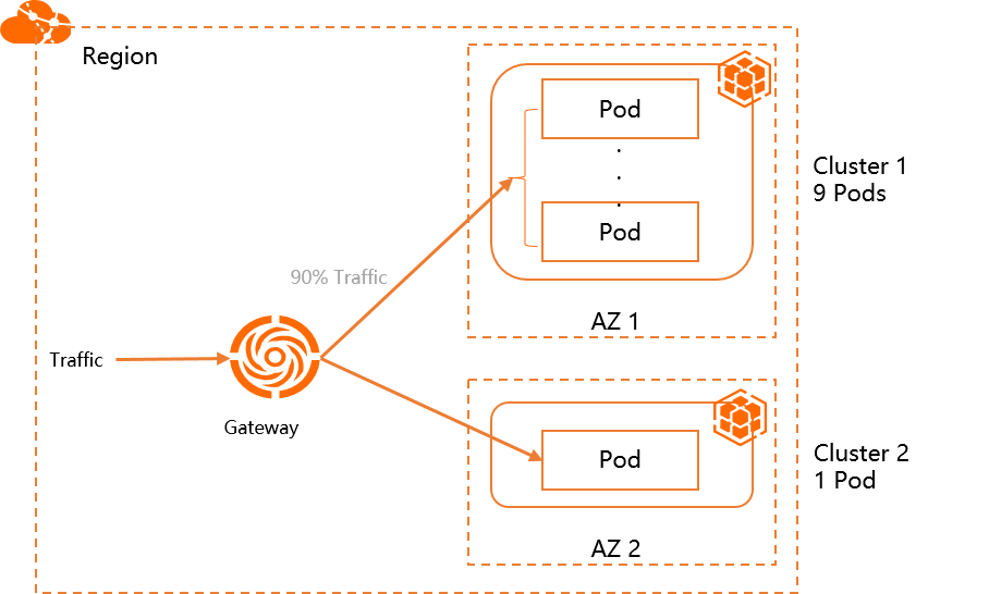
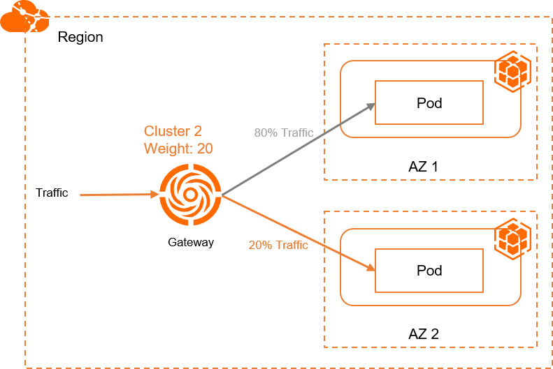
Example 5: Weight-based canary release
This example routes 10% of traffic to Cluster 2 and 90% to Cluster 1 using the nginx.ingress.kubernetes.io/canary-weight annotation. Use this pattern for canary releases.
Weight-based routing requires two Ingresses with the same host and path — one with canary: "true" and a weight value, and one without the canary annotation. The non-canary Ingress absorbs the remaining traffic.
-
Create a file named
ingress-weight.yaml. Replace${cluster1-id}and${cluster2-id}with the actual cluster IDs.Annotation Description mse.ingress.kubernetes.io/service-subsetName of the Service subset. Use a name that identifies the cluster. mse.ingress.kubernetes.io/subset-labelsID of the associated cluster. nginx.ingress.kubernetes.io/canarySet to "true"to enable canary routing.nginx.ingress.kubernetes.io/canary-weightSpecify the percentage of traffic distributed to the cluster in a range of 0 to 100. apiVersion: networking.k8s.io/v1 kind: Ingress metadata: annotations: mse.ingress.kubernetes.io/service-subset: cluster-demo-1 mse.ingress.kubernetes.io/subset-labels: | topology.istio.io/cluster ${cluster1-id} name: web-demo-weight namespace: web-demo spec: ingressClassName: mse rules: - host: example.com http: paths: - path: /svc1-w pathType: Exact backend: service: name: service1 port: number: 80 --- apiVersion: networking.k8s.io/v1 kind: Ingress metadata: annotations: mse.ingress.kubernetes.io/service-subset: cluster-demo-2 mse.ingress.kubernetes.io/subset-labels: | topology.istio.io/cluster ${cluster2-id} nginx.ingress.kubernetes.io/canary: "true" nginx.ingress.kubernetes.io/canary-weight: "10" name: web-demo-weight-canary namespace: web-demo spec: ingressClassName: mse rules: - host: example.com http: paths: - path: /svc1-w pathType: Exact backend: service: name: service1 port: number: 80Annotation reference:
-
Apply both Ingresses:
kubectl apply -f ingress-weight.yaml -nargocd -
Get the public IP address:
kubectl get ingress web-demo -nargocd -ojsonpath="{.status.loadBalancer}" -
Test weighted traffic distribution. Replace
XX.XX.XX.XXwith the gateway IP.for i in {1..50}; do curl -H "host: example.com" XX.XX.XX.XX/svc1-w; sleep 1; doneExpected output:
This is env cluster1 !
Config file is
This is env cluster1 !
Config file is
This is env cluster1 !
Config file is
This is env cluster1 !
Config file is
This is env cluster1 !
Config file is
This is env cluster1 !
Config file is
This is env cluster1 !
Config file is
This is env cluster1 !
Config file is
This is env cluster1 !
Config file is
This is env cluster1 !
Config file is
This is env cluster1 !
Config file is
This is env cluster2 !
Config file is
This is env cluster1 !
Config file is
...
The output indicates that 90% traffic is distributed to Cluster 1 and 10% traffic is distributed to Cluster 2.