Classic Load Balancer (CLB) is deployed in clusters and provides Layer 4 (TCP and UDP) and Layer 7 (HTTP and HTTPS) load balancing services. CLB synchronizes sessions and eliminates single points of failure (SPOFs) to improve redundancy and ensure service stability.
CLB uses CLB clusters to forward client requests to backend servers and receives responses from backend servers over the internal network.
Basic architecture
CLB provides load balancing services at Layer 4 and Layer 7.
At Layer 4, CLB combines the open-source Linux Virtual Server (LVS) with Keepalived to balance loads and customizes optimizations to meet cloud computing requirements.
At Layer 7, CLB uses Tengine to balance loads. Tengine is a web server project launched by Taobao. Based on NGINX, Tengine has a wide range of advanced features optimized for websites with many visits.
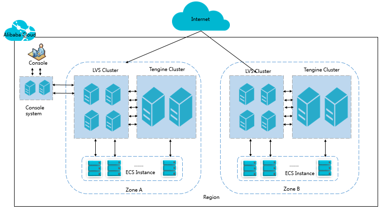
As shown in the following figure, in each region, Layer 4 CLB runs in an LVS cluster that consists of multiple LVS physical servers. This cluster deployment model strengthens the availability, stability, and scalability of CLB even when anomalies occur.
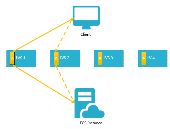
Each backend server in an LVS cluster uses multicast packets to synchronize sessions across the cluster. For example, as shown in the following figure, after the client sends three packets to the server, Session A established on LVS1 is synchronized with other servers. Solid lines indicate the active connections. Dashed lines indicate that requests are forwarded to other healthy servers (LVS2 in this case) in the event that LVS1 fails or is under maintenance. This allows you to perform hot upgrades, troubleshoot servers, and take clusters offline for maintenance without affecting the services provided by your applications.
If a connection is not established because the three-way handshake fails, or if a connection has been established but sessions are not synchronized during a hot upgrade, your services may be interrupted. In this case, you must re-initiate a connection request from the client.
Inbound traffic flow
CLB distributes inbound traffic based on the forwarding rules that you configure in the CLB console or by using API operations. The following figure shows the inbound traffic flow.
Figure 1. Inbound traffic flow

Inbound traffic that uses TCP, UDP, HTTP, or HTTPS must be forwarded through the Layer 4 cluster.
The large amount of inbound traffic is distributed evenly among all nodes in the Layer 4 cluster, and the nodes synchronize sessions to ensure high availability.
If Layer 4 listeners based on UDP or TCP are used by the CLB instance, the nodes in the Layer 4 cluster distribute requests directly to backend Elastic Compute Service (ECS) instances based on forwarding rules configured for the CLB instance.
If Layer 7 listeners based on HTTP are used by the CLB instance, the nodes in the Layer 4 cluster first distribute requests to the Layer 7 cluster. Then, the nodes in the Layer 7 cluster distribute the requests to backend ECS instances based on the forwarding rules configured for the CLB instance.
If Layer 7 listeners based on HTTPS are used by the CLB instance, requests are distributed in a similar way to how requests are distributed by a CLB instance that uses listeners based on HTTP. The difference is that the system calls the Key Server to validate certificates and decrypt data packets before requests are distributed to backend ECS instances.
Outbound traffic flow
CLB and backend ECS instances communicate over the internal network.
If backend ECS instances handle only the traffic distributed from CLB, you do not need to purchase Internet bandwidth resources, such as public IP addresses, elastic IP addresses (EIPs), Anycast EIPs, or NAT gateways, for the ECS instances.
NotePreviously created ECS instances are directly assigned public IP addresses. You can view the public IP addresses by running the
ipconfigcommand. If the ECS instances provide external services only through CLB, no traffic fees are generated for Internet traffic even if traffic statistics are read at the elastic network interfaces (ENIs).If you want your backend ECS instances to directly provide external services or access the Internet, you must configure or purchase public IP addresses, EIPs, Anycast EIPs, or NAT gateways for the instances.
The following figure shows the outbound traffic flow.
Figure 2. Outbound traffic flow

A general principle for how outbound traffic flows is that traffic goes out from where it comes in.
Traffic that flows through a CLB instance is throttled or billed on the CLB instance. You are not charged for the internal communication between a CLB instance and backend ECS instances
You are charged for traffic from EIPs or NAT gateways. You can throttle traffic speed on EIPs or NAT gateways. If public bandwidth resources are configured for ECS instances, you are charged for traffic from the ECS instances, and you can throttle traffic speed on the ECS instances.
CLB supports responsive access to the Internet. Backend ECS instances can access the Internet only if they need to respond to requests from the Internet. The requests are forwarded to the backend ECS instances by CLB instances. If your backend ECS instances need to proactively access the Internet, you must associate EIPs or use NAT gateways with the ECS instances.
The public bandwidth resources configured for ECS instances, EIPs, Anycast EIPs, and NAT gateways allow ECS instances to access the Internet or be accessed from the Internet, but the preceding resources cannot distribute traffic or balance traffic loads.
FAQ
Does the maximum bandwidth value I set when purchasing a CLB instance equal the sum of the maximum inbound and maximum outbound bandwidth?
No, it does not.
The maximum bandwidth value applies separately to both inbound and outbound traffic. Each type of traffic can independently reach the maximum bandwidth value you specify without affecting the other.
For more information, see Bandwidth limits.