This topic describes how to use Cloud Enterprise Network (CEN) and IPsec-VPN connections associated with VPN gateways to connect data centers in multiple regions to virtual private clouds (VPCs) across the globe.
Scenario
If your Alibaba Cloud account does not have a public VPN gateway, we recommend that you use IPsec-VPN connections to enable communication among networks across the world.
If your Alibaba Cloud account already has a public VPN gateway, refer to this topic to enable communication among networks across the world.
Assume that you have multiple data centers and VPCs across the world. After you connect data centers to VPCs through IPsec-VPN connections associated with VPN gateways, the VPCs can communicate only with the VPCs that are associated with VPN gateways. By default, VPCs and data centers in different regions cannot communicate with each other. The following figure shows the network connectivity between different networks.

VPC1 cannot communicate with VPC2.
Data Center 1 can communicate with VPC1. Data Center 1 and Data Center 2 can communicate with each other after they establish IPsec-VPN connections with the same VPN gateway. Data Center 1 cannot communicate with Data Center 3, Data Center 4, or VPC2.
Data Center 2 can communicate with VPC1. Data Center 1 and Data Center 2 can communicate with each other after they establish IPsec-VPN connections with the same VPN gateway. Data Center 2 cannot communicate with Data Center 3, Data Center 4, or VPC2.
Data Center 3 can communicate with VPC2. Data Center 3 and Data Center 4 can communicate with each other after they establish IPsec-VPN connections with the same VPN gateway. Data Center 3 cannot communicate with Data Center 1, Data Center 2, or VPC1.
Data Center 4 can communicate with VPC2. Data Center 3 and Data Center 4 can communicate with each other after they establish IPsec-VPN connections with the same VPN gateway. Data Center 4 cannot communicate with Data Center 1, Data Center 2, or VPC1.
If you want to enable communication among networks across the globe, you can use IPsec-VPN connections together with CEN. CEN can be used to establish high-quality and low-latency connections among VPCs and support automatic route advertising and learning. This enables cross-region VPC communication and simplifies route configurations. Data centers across the globe can also communicate with each other by using VPCs and CEN.

We recommend that you use static routing when you establish IPsec-VPN connections between data centers and VPN gateways.
Background information
The following figure shows how to use IPsec-VPN connections associated with VPN gateways and CEN to enable communication among networks across the globe. Assume that you have two data centers in Shanghai and two data centers in Silicon Valley. VPC1 is created in China (Shanghai) and VPC2 is created in US (Silicon Valley). Elastic Compute Service (ECS) instances are deployed in VPC1 and VPC2. Due to business development, you want to enable communication among Data Center 1, Data Center 2, Data Center 3, Data Center 4, VPC1, and VPC2. Data Center 1 and Data Center 2 are in Shanghai, and Data Center 3 and Data Center 4 are in Silicon Valley.

Subnetting
Make sure that the CIDR blocks do not overlap with each other.
VPC subnetting
VPC | Region | VPC CIDR block | ECS instance IP address |
VPC1 | China (Shanghai) |
| ECS1 IP address: 192.168.99.48 |
VPC2 | US (Silicon Valley) |
| ECS2 IP address: 10.0.10.33 |
Data center subnetting
Data center | Region | CIDR block to communicate with VPC | IP address of on-premises gateway | Client IP address to communicate with other networks |
Data Center 1 | China (Shanghai) | 172.16.10.0/24 |
| 172.16.10.207 |
Data Center 2 | China (Shanghai) | 172.16.40.0/24 |
| 172.16.40.60 |
Data Center 3 | US (Silicon Valley) | 10.10.10.0/24 |
| 10.10.10.201 |
Data Center 4 | US (Silicon Valley) | 10.30.66.0/24 |
| 10.30.66.11 |
Preparations
VPC1 is created in China (Shanghai), VPC2 is created in US (Silicon Valley), and ECS instances are deployed in both VPCs. For more information, see Create a VPC with an IPv4 CIDR block.
A public VPN gateway is created in each of China (Shanghai) and US (Silicon Valley), and IPsec-VPN is enabled for each VPN gateway. For more information, see Enable IPsec-VPN.
NoteIn this example, VPN gateways that support the dual-tunnel mode are used. If your VPN gateway supports only single-tunnel IPsec-VPN connections, we recommend that you upgrade your VPN gateway to enable the dual-tunnel mode. The dual-tunnel mode supports cross-zone disaster recovery. For more information, see Upgrade to dual-tunnel mode.
The following table describes the information about the VPN gateways, including the associated VPCs and assigned IP addresses. The IP addresses are used to establish IPsec-VPN connections.
VPN gateway name
Region
Gateway type
Network type
Tunnel mode
Associated VPC
VPN gateway IP address
VPN Gateway 1
China (Shanghai)
Standard
Public
Dual-tunnel
VPC1
IP address of IPsec-VPN Connection 1: 47.XX.XX.87
IP address of IPsec-VPN Connection 2: 47.XX.XX.78
VPN Gateway 2
US (Silicon Valley)
Standard
Public
Dual-tunnel
VPC2
IP address of IPsec-VPN Connection 1: 47.XX.XX.207
IP address of IPsec-VPN Connection 2: 47.XX.XX.15
Procedure
Step 1: Create a customer gateway
You need to create a customer gateway to register the public IP address of the on-premises gateway device with Alibaba Cloud. The data center can use only registered public IP addresses to establish an IPsec-VPN connection to Alibaba Cloud.
Log on to the VPN Gateway console.
In the navigation pane on the left, choose .
In the top navigation bar, select the region in which you want to create the customer gateways.
NoteThe customer gateway and the VPN gateway to be connected must be deployed in the same region.
On the Customer Gateway page, click Create Customer Gateway.
In the Create Customer Gateway panel, configure the following parameters and click OK.
You need to create eight customer gateways and register eight public IP addresses of four on-premises gateways with Alibaba Cloud. The following table describes only the key parameters. Use the default values for other parameters. For more information, see Customer gateway.
Customer gateway region
Customer gateway name
Customer gateway IP address
China (Shanghai)
Customer Gateway 1
In this example, Public IP Address 1 47.XX.XX.23 is used for On-premises Gateway 1.
Customer Gateway 2
In this example, Public IP Address 2 47.XX.XX.32 is used for On-premises Gateway 1.
Customer Gateway 3
In this example, Public IP Address 1 47.XX.XX.69 is used for On-premises Gateway 2.
Customer Gateway 4
In this example, Public IP Address 2 47.XX.XX.71 is used for On-premises Gateway 2.
US (Silicon Valley)
Customer Gateway 5
In this example, Public IP Address 1 57.XX.XX.11 is used for On-premises Gateway 3.
Customer Gateway 6
In this example, Public IP Address 2 47.XX.XX.191 is used for On-premises Gateway 3.
Customer Gateway 7
In this example, Public IP Address 1 57.XX.XX.22 is used for On-premises Gateway 4.
Customer Gateway 8
In this example, Public IP Address 2 47.XX.XX.234 is used for On-premises Gateway 4.
Step 2: Create an IPsec-VPN connection
You must create two IPsec-VPN connections on each VPN gateway. When you create an IPsec-VPN connection, you need to specify the tunnel encryption algorithm and the peer data center. Each IPsec-VPN connection corresponds to one data center.
In the left navigation pane, choose .
On the IPsec Connections page, click Bind VPN Gateway.
On the Create Ipsec-vpn Connection (VPN) page, configure the following parameters and click OK.
The following table describes only the key parameters. Use the default values for other parameters. For more information, see Configure IPsec-VPN connections.
Parameter
IPsec-VPN Connection 1
IPsec-VPN Connection 2
IPsec-VPN Connection 3
IPsec-VPN Connection 4
Name
IPsec1 is used in this example.
IPsec2 is used in this example.
IPsec3 is used in this example.
IPsec4 is used in this example.
Region
China (Shanghai)
China (Shanghai)
US (Silicon Valley)
US (Silicon Valley)
Bind VPN Gateway
Select VPN Gateway 1.
Select VPN Gateway 1.
Select VPN Gateway 2.
Select VPN Gateway 2.
Routing Mode
Destination Routing Mode is selected because multiple CIDR blocks need to communicate with each other.
Effective Immediately
In this example, the default value Yes is selected. IPsec negotiations are immediately started after the IPsec-VPN connection is created.
Tunnel 1
Customer Gateway
Select Customer Gateway 1.
Select Customer Gateway 3.
Select Customer Gateway 5.
Select Customer Gateway 7.
Pre-Shared Key
ImportantThe pre-shared key of the IPsec-VPN connection must be the same as the pre-shared key of the peer gateway device. Otherwise, the IPsec-VPN connection cannot be established.
fddsFF111**** is used in this example.
fddsFF333**** is used in this example.
fddsFF555**** is used in this example.
fddsFF777**** is used in this example.
Encryption Configuration
Use the default values of parameters except for the following parameters.
Set the DH Group parameter in the IKE Configurations section to group14.
Set the DH Group parameter in the IPsec Configurations section to group14.
NoteYou need to select encryption parameters based on the on-premises gateway device to ensure that the encryption configurations for the IPsec connection are the same as those for the on-premises gateway device.
Tunnel 2
Customer Gateway
Select Customer Gateway 2.
Select Customer Gateway 4.
Select Customer Gateway 6.
Select Customer Gateway 8.
Pre-Shared Key
fddsFF222**** is used in this example.
fddsFF444**** is used in this example.
fddsFF666**** is used in this example.
fddsFF888**** is used in this example.
Encryption Configuration
Use the default values of parameters except for the following parameters.
Set the DH Group parameter in the IKE Configurations section to group14.
Set the DH Group parameter in the IPsec Configurations section to group14.
NoteYou need to select encryption parameters based on the on-premises gateway device to ensure that the encryption configurations for the IPsec connection are the same as those for the on-premises gateway device.
In the Created message, click OK.
On the IPsec Connections page, find the IPsec-VPN connection that you create and click Generate Peer Configuration in the Actions column.
The configurations of the IPsec peer refer to the VPN configurations that you need to add when you create the IPsec-VPN connection. In this example, you need to add the VPN configurations to the gateway device of the data center.
In the IPsec Connection Configuration dialog box, copy and save the configurations to an on-premises machine. The configurations are required when you configure the gateway device of the data center.
The following table describes the relationships among the VPCs, VPN gateways, IPsec-VPN connections, data centers, and customer gateways.
VPC
VPN gateway
IPsec-VPN connection
Tunnel
Customer gateway associated with the tunnel
Peer data center
VPC1
VPN Gateway 1
IPsec-VPN Connection 1
Active tunnel
Customer Gateway 1
Data Center 1
Standby Tunnel
Customer Gateway 2
IPsec-VPN Connection 2
Active Tunnel
Customer Gateway 3
Data Center 2
Standby Tunnel
Customer Gateway 4
VPC2
VPN Gateway 2
IPsec-VPN Connection 3
Active Tunnel
Customer Gateway 5
Data Center 3
Standby Tunnel
Customer Gateway 6
IPsec-VPN Connection 4
Active Tunnel
Customer Gateway 7
Data Center 4
Standby Tunnel
Customer Gateway 8
Step 3: Configure routes for the VPN gateways
After you create an IPsec-VPN connection, you need to add routes that point to the data center on a VPN gateway. In this example, Destination Routing Mode is selected. For more information, see Configure routes for a VPN gateway.
In the left navigation pane, choose .
In the top navigation bar, select the region where the VPN gateway instance resides.
On the VPN Gateway page, click the ID of the VPN gateway that you want to manage.
On the Destination-based Route Table tab, click Add Route Entry.
In the Add Route Entry panel, configure the following parameters and click OK.
On VPN Gateway 1, add routes that point to Data Center 1 and Data Center 2. On VPN Gateway 2, add routes that point to Data Center 3 and Data Center 4.
Parameter
VPN Gateway 1
VPN Gateway 2
Destination CIDR block
Enter the CIDR block 172.16.10.0/24 of Data Center 1.
Enter the CIDR block 172.16.40.0/24 of Data Center 2.
Enter the CIDR block 10.10.0.0/16 of Data Center 3.
Enter the CIDR block 10.30.0.0/16 of Data Center 4.
Next Hop Type
In this example, IPsec Connection is selected.
In this example, IPsec Connection is selected.
In this example, IPsec Connection is selected.
Select IPsec-VPN Connection.
Next Hop
Select IPsec-VPN Connection 1.
Select IPsec-VPN Connection 2.
Select IPsec-VPN Connection 3.
Select IPsec-VPN Connection 4.
Advertise to VPC
Use the default value Yes.
After the destination-based route is added, routes of Data Center 1 and Data Center 2 are automatically advertised to the system route table of VPC1.
Use the default value Yes.
After the destination-based route is added, routes of Data Center 3 and Data Center 4 are automatically advertised to the system route table of VPC2.
Step 4: Configure the on-premises gateways
After you complete the preceding steps, you need to add VPN and routing configurations to the gateway devices in the data center to allow the gateway devices to connect to the IPsec-VPN connection. Then, network traffic is transmitted from the active tunnel to other networks by default. If the active tunnel is down, the standby tunnel automatically takes over.
In this example, the software Adaptive Security Appliance (ASA) 9.19.1 is used to describe how to configure a Cisco firewall. The commands may vary with software versions. Consult the documentation or your vendor based on your actual environment during operations. For more information, see Configure local gateways.
The following content contains third-party product information, which is only for reference. Alibaba Cloud does not make guarantees or other forms of commitments for the performance and reliability of third-party products, or the potential impacts of operations performed by using these products.
Configure On-premises Gateway Device 1
Log on to the CLI of the Cisco firewall and enter the configuration mode.
ciscoasa> enable
Password: ********             # Enter the password for entering the enable mode.
ciscoasa# configure terminal   # Enter the configuration mode.
ciscoasa(config)#
View the interface configurations and route configurations for Internet access.
Verify that the interfaces are configured and enabled on the Cisco firewall. In this example, the following interface configurations are used:
ciscoasa(config)# show running-config interface
!
interface GigabitEthernet0/0
 nameif outside1                            # The name of the GigabitEthernet 0/0 interface.
 security-level 0
 ip address 47.XX.XX.23 255.255.255.255    # The public IP address of the GigabitEthernet 0/0 interface.
!
interface GigabitEthernet0/1                # The interface that connects to the data center.
 nameif private                             # The name of the GigabitEthernet 0/1 interface.
 security-level 100                         # The security level of the private interface that connects to the data center, which is lower than that of a public interface.
 ip address 172.16.10.217 255.255.255.0    # The IP address of the GigabitEthernet 0/1 interface.
!
interface GigabitEthernet0/2
 nameif outside2                            # The name of the GigabitEthernet 0/2 interface.
 security-level 0
 ip address 47.XX.XX.32 255.255.255.255    # The public IP address of the GigabitEthernet 0/2 interface.
!

route outside1 47.XX.XX.87 255.255.255.255 192.XX.XX.172 # The route for accessing the public IP address of Tunnel 1 on Alibaba Cloud. The next hop is a public IP address.
route outside2 47.XX.XX.78 255.255.255.255 192.XX.XX.158  # The route for accessing the public IP address of Tunnel 2 on Alibaba Cloud. The next hop is a public IP address.
route private 172.16.10.0 255.255.255.0 172.16.10.216          # The route that points to the data center.
Enable the IKEv2 feature for the public interfaces.
crypto ikev2 enable outside1
crypto ikev2 enable outside2
Create an IKEv2 policy and specify the authentication algorithm, encryption algorithm, DH group, and SA lifetime in the IKE phase on the Cisco firewall. The values must be the same as those on Alibaba Cloud.
ImportantWhen you configure an IPsec-VPN connection on Alibaba Cloud, you can specify only one value for the encryption algorithm, authentication algorithm, and DH group in the IKE phase. We recommend that you specify only one value for the encryption algorithm, authentication algorithm, and DH group in the IKE phase on the Cisco firewall. The values must be the same as those on Alibaba Cloud.
crypto ikev2 policy 10
 encryption aes             # Specify the encryption algorithm.
 integrity sha              # Specify the authentication algorithm.
 group 14                   # Specify the DH group.
 prf sha                    # The value of the prf parameter must be the same as that of the integrity parameter. By default, these values are the same on Alibaba Cloud.
 lifetime seconds 86400     # Specify the SA lifetime.
Create an IPsec proposal and profile, and specify the encryption algorithm, authentication algorithm, DH group, and SA lifetime in the IPsec phase on the Cisco firewall. The values must be the same as those on Alibaba Cloud.
ImportantWhen you configure an IPsec-VPN connection on Alibaba Cloud, you can specify only one value for the encryption algorithm, authentication algorithm, and DH group in the IPsec phase. We recommend that you specify only one value for the encryption algorithm, authentication algorithm, and DH group in the IPsec phase on the Cisco firewall. The values must be the same as those on Alibaba Cloud.
crypto ipsec ikev2 ipsec-proposal ALIYUN-PROPOSAL    # Create an IPsec proposal.
 protocol esp encryption aes                         # Specify the encryption algorithm. The Encapsulating Security Payload (ESP) protocol is used on Alibaba Cloud. Therefore, use the ESP protocol.
 protocol esp integrity sha-1                        # Specify the authentication algorithm. The ESP protocol is used on Alibaba Cloud. Therefore, use the ESP protocol.
crypto ipsec profile ALIYUN-PROFILE
 set ikev2 ipsec-proposal ALIYUN-PROPOSAL            # Create an IPsec profile and apply the proposal that is created.
 set ikev2 local-identity address                    # Set the format of the local ID to IP address, which is the same as the format of the remote ID on Alibaba Cloud.
 set pfs group14                                     # Specify the Perfect Forward Secrecy (PFS) and DH group.
 set security-association lifetime seconds 86400     # Specify the time-based SA lifetime.
 set security-association lifetime kilobytes unlimited # Disable the traffic-based SA lifetime.
Create tunnel groups and specify the pre-shared keys for tunnels, which must be the same as those on the Alibaba Cloud side.
tunnel-group 47.XX.XX.87 type ipsec-l2l                   # Specify the encapsulation mode l2l for Tunnel 1.
tunnel-group 47.XX.XX.87 ipsec-attributes
 ikev2 remote-authentication pre-shared-key fddsFF111****  # Specify the peer pre-shared key for Tunnel 1, which is the pre-shared key on the Alibaba Cloud side.
 ikev2 local-authentication pre-shared-key fddsFF111**** # Specify the local pre-shared key for Tunnel 1, which must be the same as that on Alibaba Cloud.
!
tunnel-group 47.XX.XX.78 type ipsec-l2l                  # Specify the encapsulation mode l2l for Tunnel 2.
tunnel-group 47.XX.XX.78 ipsec-attributes
 ikev2 remote-authentication pre-shared-key fddsFF222****  # Specify the peer pre-shared key for Tunnel 2, which is the pre-shared key on the Alibaba Cloud side.
 ikev2 local-authentication pre-shared-key fddsFF222****   # Specify the local pre-shared key for Tunnel 2, which must be the same as that on Alibaba Cloud.
!
Create tunnel interfaces.
interface Tunnel1                                  # Create an interface for Tunnel 1.
 nameif ALIYUN1
 ip address 169.254.10.2 255.255.255.252           # Specify the IP address of the interface.
 tunnel source interface outside1                  # Specify the IP address of the GigabitEthernet 0/0 interface as the source address of Tunnel 1.
 tunnel destination 47.XX.XX.87                   # Specify the public IP address of Tunnel 1 on Alibaba Cloud as the destination address of Tunnel 1.
 tunnel mode ipsec ipv4
 tunnel protection ipsec profile ALIYUN-PROFILE    # Apply the IPsec profile ALIYUN-PROFILE on Tunnel 1.
 no shutdown                                       # Enable the interface for Tunnel 1.
!
interface Tunnel2                                  # Create an interface for Tunnel 2.
 nameif ALIYUN2
 ip address 169.254.20.2 255.255.255.252           # Specify the IP address of the interface.
 tunnel source interface outside2                  # Specify the IP address of the GigabitEthernet 0/2 interface as the source address of Tunnel 2.
 tunnel destination 47.XX.XX.78                   # Specify the public IP address of Tunnel 2 on Alibaba Cloud as the destination address of Tunnel 2.
 tunnel mode ipsec ipv4
 tunnel protection ipsec profile ALIYUN-PROFILE # Apply the IPsec profile ALIYUN-PROFILE on Tunnel 2.
 no shutdown                                       # Enable the interface for Tunnel 2.
!
Configure static routes that point to other networks.
Specify that traffic from Data Center 1 is preferentially forwarded through the interface of Tunnel 1. This route has a high priority.
route ALIYUN1 172.16.40.0 255.255.255.0 47.XX.XX.87 4  #The route that points to Data Center 2.
route ALIYUN1 10.30.0.0 255.255.0.0 47.XX.XX.87 4      #The route that points to Data Center 4.
route ALIYUN1 10.10.0.0 255.255.0.0 47.XX.XX.87 4      #The route that points to Data Center 3.
route ALIYUN1 10.0.0.0 255.255.0.0 47.XX.XX.87 4       #The route that points to VPC2.
route ALIYUN1 192.168.99.0 255.255.255.0 47.XX.XX.87 4 The route that points to VPC1.

Specify that traffic from Data Center 1 is preferentially forwarded through the interface of Tunnel 2. The priority of this route is lower than that of the route that points to Tunnel 1.
route ALIYUN2 172.16.40.0 255.255.255.0 47.XX.XX.78 5
route ALIYUN2 10.30.0.0 255.255.0.0 47.XX.XX.78 5
route ALIYUN2 10.10.0.0 255.255.0.0 47.XX.XX.78 5
route ALIYUN2 10.0.0.0 255.255.0.0 47.XX.XX.78 5
route ALIYUN2 192.168.99.0 255.255.255.0 47.XX.XX.78 5
Configure routes on Data Center 1 so that the clients in Data Center 1 can access other networks through the Cisco firewall.
Configure On-premises Gateway 2
Log on to the CLI of the Cisco firewall and enter the configuration mode.
ciscoasa> enable
Password: ********             # Enter the password for entering the enable mode.
ciscoasa# configure terminal   # Enter the configuration mode.
ciscoasa(config)#
View the interface configurations and route configurations for Internet access.
Verify that the interfaces are configured and enabled on the Cisco firewall. In this example, the following interface configurations are used:
ciscoasa(config)# show running-config interface
!
interface GigabitEthernet0/0
 nameif outside1                            # The name of the GigabitEthernet 0/0 interface.
 security-level 0
 ip address 47.XX.XX.69 255.255.255.255    # The public IP address of the GigabitEthernet 0/0 interface.
!
interface GigabitEthernet0/1                # The interface that connects to the data center.
 nameif private                             # The name of the GigabitEthernet 0/1 interface.
 security-level 100                         # The security level of the private interface that connects to the data center, which is lower than that of a public interface.
 ip address 172.16.40.217 255.255.255.0    # The IP address of the GigabitEthernet 0/1 interface.
!
interface GigabitEthernet0/2
 nameif outside2                            # The name of the GigabitEthernet 0/2 interface.
 security-level 0
 ip address 47.XX.XX.71 255.255.255.255    # The public IP address of the GigabitEthernet 0/2 interface.
!

route outside1 47.XX.XX.87 255.255.255.255 192.XX.XX.172 # The route for accessing the public IP address of Tunnel 1 on Alibaba Cloud. The next hop is a public IP address.
route outside2 47.XX.XX.78 255.255.255.255 192.XX.XX.158  # The route for accessing the public IP address of Tunnel 2 on Alibaba Cloud. The next hop is a public IP address.
route private 172.16.40.0 255.255.255.0 172.16.40.216           # The route that points to the data center.
Enable the IKEv2 feature for the public interfaces.
crypto ikev2 enable outside1
crypto ikev2 enable outside2
Create an IKEv2 policy and specify the authentication algorithm, encryption algorithm, DH group, and SA lifetime in the IKE phase on the Cisco firewall. The values must be the same as those on Alibaba Cloud.
ImportantWhen you configure an IPsec-VPN connection on Alibaba Cloud, you can specify only one value for the encryption algorithm, authentication algorithm, and DH group in the IKE phase. We recommend that you specify only one value for the encryption algorithm, authentication algorithm, and DH group in the IKE phase on the Cisco firewall. The values must be the same as those on Alibaba Cloud.
crypto ikev2 policy 10
 encryption aes             # Specify the encryption algorithm.
 integrity sha              # Specify the authentication algorithm.
 group 14                   # Specify the DH group.
 prf sha                    # The value of the prf parameter must be the same as that of the integrity parameter. By default, these values are the same on Alibaba Cloud.
 lifetime seconds 86400     # Specify the SA lifetime.
Create an IPsec proposal and profile, and specify the encryption algorithm, authentication algorithm, DH group, and SA lifetime in the IPsec phase on the Cisco firewall. The values must be the same as those on Alibaba Cloud.
ImportantWhen you configure an IPsec-VPN connection on Alibaba Cloud, you can specify only one value for the encryption algorithm, authentication algorithm, and DH group in the IPsec phase. We recommend that you specify only one value for the encryption algorithm, authentication algorithm, and DH group in the IPsec phase on the Cisco firewall. The values must be the same as those on Alibaba Cloud.
crypto ipsec ikev2 ipsec-proposal ALIYUN-PROPOSAL    # Create an IPsec proposal.
 protocol esp encryption aes                         # Specify the encryption algorithm. The Encapsulating Security Payload (ESP) protocol is used on Alibaba Cloud. Therefore, use the ESP protocol.
 protocol esp integrity sha-1                        # Specify the authentication algorithm. The ESP protocol is used on Alibaba Cloud. Therefore, use the ESP protocol.
crypto ipsec profile ALIYUN-PROFILE
 set ikev2 ipsec-proposal ALIYUN-PROPOSAL            # Create an IPsec profile and apply the proposal that is created.
 set ikev2 local-identity address                    # Set the format of the local ID to IP address, which is the same as the format of the remote ID on Alibaba Cloud.
 set pfs group14                                     # Specify the Perfect Forward Secrecy (PFS) and DH group.
 set security-association lifetime seconds 86400     # Specify the time-based SA lifetime.
 set security-association lifetime kilobytes unlimited # Disable the traffic-based SA lifetime.
Create tunnel groups and specify the pre-shared keys for tunnels, which must be the same as those on the Alibaba Cloud side.
tunnel-group 47.XX.XX.87 type ipsec-l2l                   # Specify the encapsulation mode l2l for Tunnel 1.
tunnel-group 47.XX.XX.87 ipsec-attributes
 ikev2 remote-authentication pre-shared-key fddsFF333****  # Specify the peer pre-shared key for Tunnel 1, which is the pre-shared key on the Alibaba Cloud side.
 ikev2 local-authentication pre-shared-key fddsFF333**** # Specify the local pre-shared key for Tunnel 1, which must be the same as that on Alibaba Cloud.
!
tunnel-group 47.XX.XX.78 type ipsec-l2l                  # Specify the encapsulation mode l2l for Tunnel 2.
tunnel-group 47.XX.XX.78 ipsec-attributes
 ikev2 remote-authentication pre-shared-key fddsFF444****  # Specify the peer pre-shared key for Tunnel 2, which is the pre-shared key on the Alibaba Cloud side.
 ikev2 local-authentication pre-shared-key fddsFF444****   # Specify the local pre-shared key for Tunnel 2, which must be the same as that on Alibaba Cloud.
!
Create tunnel interfaces.
interface Tunnel1                                  # Create an interface for Tunnel 1.
 nameif ALIYUN1
 ip address 169.254.11.2 255.255.255.252           # Specify the IP address of the interface.
 tunnel source interface outside1                  # Specify the IP address of the GigabitEthernet 0/0 interface as the source address of Tunnel 1.
 tunnel destination 47.XX.XX.87                   # Specify the public IP address of Tunnel 1 on Alibaba Cloud as the destination address of Tunnel 1.
 tunnel mode ipsec ipv4
 tunnel protection ipsec profile ALIYUN-PROFILE    # Apply the IPsec profile ALIYUN-PROFILE on Tunnel 1.
 no shutdown                                       # Enable the interface for Tunnel 1.
!
interface Tunnel2                                  # Create an interface for Tunnel 2.
 nameif ALIYUN2
 ip address 169.254.21.2 255.255.255.252          # Specify the IP address of the interface.
 tunnel source interface outside2                  # Specify the IP address of the GigabitEthernet 0/2 interface as the source address of Tunnel 2.
 tunnel destination 47.XX.XX.78                   # Specify the public IP address of Tunnel 2 on Alibaba Cloud as the destination address of Tunnel 2.
 tunnel mode ipsec ipv4
 tunnel protection ipsec profile ALIYUN-PROFILE # Apply the IPsec profile ALIYUN-PROFILE on Tunnel 2.
 no shutdown                                       # Enable the interface for Tunnel 2.
!
Configure static routes that point to other networks.
Specify that traffic from Data Center 2 is preferentially forwarded through the interface of Tunnel 1. This route has a high priority.
route ALIYUN1 172.16.10.0 255.255.255.0 47.XX.XX.87 4      #The route that points to Data Center 1.
route ALIYUN1 10.30.0.0 255.255.0.0 47.XX.XX.87 4      #The route that points to Data Center 4.
route ALIYUN1 10.10.0.0 255.255.0.0 47.XX.XX.87 4      #The route that points to Data Center 3.
route ALIYUN1 10.0.0.0 255.255.0.0 47.XX.XX.87 4       #The route that points to VPC2.
route ALIYUN1 192.168.99.0 255.255.255.0 47.XX.XX.87 4 The route that points to VPC1.

Specify that traffic from Data Center 2 is preferentially forwarded through the interface of Tunnel 2. The priority of this route is lower than that of the route that points to Tunnel 1.
route ALIYUN2 172.16.10.0 255.255.255.0 47.XX.XX.78 5
route ALIYUN2 10.30.0.0 255.255.0.0 47.XX.XX.78 5
route ALIYUN2 10.10.0.0 255.255.0.0 47.XX.XX.78 5
route ALIYUN2 10.0.0.0 255.255.0.0 47.XX.XX.78 5
route ALIYUN2 192.168.99.0 255.255.255.0 47.XX.XX.78 5
Configure routes on Data Center 2 so that the clients in Data Center 2 can access other networks through the Cisco firewall.
Configuration example for On-premises Gateway Device 3
Log on to the CLI of the Cisco firewall and enter the configuration mode.
ciscoasa> enable
Password: ********             # Enter the password for entering the enable mode.
ciscoasa# configure terminal   # Enter the configuration mode.
ciscoasa(config)#
View the interface configurations and route configurations for Internet access.
Verify that the interfaces are configured and enabled on the Cisco firewall. In this example, the following interface configurations are used:
ciscoasa(config)# show running-config interface
!
interface GigabitEthernet0/0
 nameif outside1                            # The name of the GigabitEthernet 0/0 interface.
 security-level 0
 ip address 57.XX.XX.11 255.255.255.255   # The public IP address of the GigabitEthernet 0/0 interface.
!
interface GigabitEthernet0/1                # The interface that connects to the data center.
 nameif private                             # The name of the GigabitEthernet 0/1 interface.
 security-level 100                         # The security level of the private interface that connects to the data center, which is lower than that of a public interface.
 ip address 10.10.10.217 255.255.255.0    # The IP address of the GigabitEthernet 0/1 interface.
!
interface GigabitEthernet0/2
 nameif outside2                            # The name of the GigabitEthernet 0/2 interface.
 security-level 0
 ip address 57.XX.XX.191 255.255.255.255    # The public IP address of the GigabitEthernet 0/2 interface.
!

route outside1 47.XX.XX.207 255.255.255.255 192.XX.XX.172 # The route for accessing the public IP address of Tunnel 1 on Alibaba Cloud. The next hop is a public IP address.
route outside2 47.XX.XX.15 255.255.255.255 192.XX.XX.158  # The route for accessing the public IP address of Tunnel 2 on Alibaba Cloud. The next hop is a public IP address.
route private 10.10.10.0 255.255.255.0 10.10.10.216          # The route that points to the data center.
Enable the IKEv2 feature for the public interfaces.
crypto ikev2 enable outside1
crypto ikev2 enable outside2
Create an IKEv2 policy and specify the authentication algorithm, encryption algorithm, DH group, and SA lifetime in the IKE phase on the Cisco firewall. The values must be the same as those on Alibaba Cloud.
ImportantWhen you configure an IPsec-VPN connection on Alibaba Cloud, you can specify only one value for the encryption algorithm, authentication algorithm, and DH group in the IKE phase. We recommend that you specify only one value for the encryption algorithm, authentication algorithm, and DH group in the IKE phase on the Cisco firewall. The values must be the same as those on Alibaba Cloud.
crypto ikev2 policy 10
 encryption aes             # Specify the encryption algorithm.
 integrity sha              # Specify the authentication algorithm.
 group 14                   # Specify the DH group.
 prf sha                    # The value of the prf parameter must be the same as that of the integrity parameter. By default, these values are the same on Alibaba Cloud.
 lifetime seconds 86400     # Specify the SA lifetime.
Create an IPsec proposal and profile, and specify the encryption algorithm, authentication algorithm, DH group, and SA lifetime in the IPsec phase on the Cisco firewall. The values must be the same as those on Alibaba Cloud.
ImportantWhen you configure an IPsec-VPN connection on Alibaba Cloud, you can specify only one value for the encryption algorithm, authentication algorithm, and DH group in the IPsec phase. We recommend that you specify only one value for the encryption algorithm, authentication algorithm, and DH group in the IPsec phase on the Cisco firewall. The values must be the same as those on Alibaba Cloud.
crypto ipsec ikev2 ipsec-proposal ALIYUN-PROPOSAL    # Create an IPsec proposal.
 protocol esp encryption aes                         # Specify the encryption algorithm. The Encapsulating Security Payload (ESP) protocol is used on Alibaba Cloud. Therefore, use the ESP protocol.
 protocol esp integrity sha-1                        # Specify the authentication algorithm. The ESP protocol is used on Alibaba Cloud. Therefore, use the ESP protocol.
crypto ipsec profile ALIYUN-PROFILE
 set ikev2 ipsec-proposal ALIYUN-PROPOSAL            # Create an IPsec profile and apply the proposal that is created.
 set ikev2 local-identity address                    # Set the format of the local ID to IP address, which is the same as the format of the remote ID on Alibaba Cloud.
 set pfs group14                                     # Specify the Perfect Forward Secrecy (PFS) and DH group.
 set security-association lifetime seconds 86400     # Specify the time-based SA lifetime.
 set security-association lifetime kilobytes unlimited # Disable the traffic-based SA lifetime.
Create tunnel groups and specify the pre-shared keys for tunnels, which must be the same as those on the Alibaba Cloud side.
tunnel-group 47.XX.XX.207 type ipsec-l2l                   # Specify the encapsulation mode l2l for Tunnel 1.
tunnel-group 47.XX.XX.207 ipsec-attributes
 ikev2 remote-authentication pre-shared-key fddsFF555****  # Specify the peer pre-shared key for Tunnel 1, which is the pre-shared key on the Alibaba Cloud side.
 ikev2 local-authentication pre-shared-key fddsFF555**** # Specify the local pre-shared key for Tunnel 1, which must be the same as that on Alibaba Cloud.
!
tunnel-group 47.XX.XX.15 type ipsec-l2l                  # Specify the encapsulation mode l2l for Tunnel 2.
tunnel-group 47.XX.XX.15 ipsec-attributes
 ikev2 remote-authentication pre-shared-key fddsFF666****  # Specify the peer pre-shared key for Tunnel 2, which is the pre-shared key on the Alibaba Cloud side.
 ikev2 local-authentication pre-shared-key fddsFF666****   # Specify the local pre-shared key for Tunnel 2, which must be the same as that on Alibaba Cloud.
!
Create tunnel interfaces.
interface Tunnel1                                  # Create an interface for Tunnel 1.
 nameif ALIYUN1
 ip address 169.254.12.2 255.255.255.252           # Specify the IP address of the interface.
 tunnel source interface outside1                  # Specify the IP address of the GigabitEthernet 0/0 interface as the source address of Tunnel 1.
 tunnel destination 47.XX.XX.207                   # Specify the public IP address of Tunnel 1 on Alibaba Cloud as the destination address of Tunnel 1.
 tunnel mode ipsec ipv4
 tunnel protection ipsec profile ALIYUN-PROFILE    # Apply the IPsec profile ALIYUN-PROFILE on Tunnel 1.
 no shutdown                                       # Enable the interface for Tunnel 1.
!
interface Tunnel2                                  # Create an interface for Tunnel 2.
 nameif ALIYUN2
 ip address 169.254.22.2 255.255.255.252           # Specify the IP address of the interface.
 tunnel source interface outside2                  # Specify the IP address of the GigabitEthernet 0/2 interface as the source address of Tunnel 2.
 tunnel destination 47.XX.XX.15                   # Specify the public IP address of Tunnel 2 on Alibaba Cloud as the destination address of Tunnel 2.
 tunnel mode ipsec ipv4
 tunnel protection ipsec profile ALIYUN-PROFILE # Apply the IPsec profile ALIYUN-PROFILE on Tunnel 2.
 no shutdown                                       # Enable the interface for Tunnel 2.
!
Configure static routes that point to other networks.
Specify that traffic from Data Center 3 is preferentially forwarded through the interface of Tunnel 1. This route has a high priority.
route ALIYUN1 172.16.40.0 255.255.255.0 47.XX.XX.207 4  #The route that points to Data Center 2.
route ALIYUN1 10.30.0.0 255.255.0.0 47.XX.XX.207 4      #The route that points to Data Center 4.
route ALIYUN1 172.16.10.0 255.255.255.0 47.XX.XX.207 4  #The route that points to Data Center 1.
route ALIYUN1 10.0.0.0 255.255.0.0 47.XX.XX.207 4       #The route that points to Data VPC2.
route ALIYUN1 192.168.99.0 255.255.255.0 47.XX.XX.207 4 #The route that points to VPC1.

Specify that traffic from Data Center 3 is preferentially forwarded through the interface of Tunnel 2. The priority of this route is lower than that of the route that points to Tunnel 1.
route ALIYUN2 172.16.40.0 255.255.255.0 47.XX.XX.15 5
route ALIYUN2 10.30.0.0 255.255.0.0 47.XX.XX.15 5
route ALIYUN2 172.16.10.0 255.255.255.0 47.XX.XX.15 5
route ALIYUN2 10.0.0.0 255.255.0.0 47.XX.XX.15 5
route ALIYUN2 192.168.99.0 255.255.255.0 47.XX.XX.15 5
Configure routes on Data Center 3 so that the clients in Data Center 3 can access other networks through the Cisco firewall.
Configure On-premises Gateway 4
Log on to the CLI of the Cisco firewall and enter the configuration mode.
ciscoasa> enable
Password: ********             # Enter the password for entering the enable mode.
ciscoasa# configure terminal   # Enter the configuration mode.
ciscoasa(config)#
View the interface configurations and route configurations for Internet access.
Verify that the interfaces are configured and enabled on the Cisco firewall. In this example, the following interface configurations are used:
ciscoasa(config)# show running-config interface
!
interface GigabitEthernet0/0
 nameif outside1                            # The name of the GigabitEthernet 0/0 interface.
 security-level 0
 ip address 57.XX.XX.22 255.255.255.255    # The public IP address of the GigabitEthernet 0/0 interface.
!
interface GigabitEthernet0/1                # The interface that connects to the data center.
 nameif private                             # The name of the GigabitEthernet 0/1 interface.
 security-level 100                         # The security level of the private interface that connects to the data center, which is lower than that of a public interface.
 ip address 10.30.66.217 255.255.255.0    # The IP address of the GigabitEthernet 0/1 interface.
!
interface GigabitEthernet0/2
 nameif outside2                            # The name of the GigabitEthernet 0/2 interface.
 security-level 0
 ip address 57.XX.XX.234 255.255.255.255    # The public IP address of the GigabitEthernet 0/2 interface.
!

route outside1 47.XX.XX.207 255.255.255.255 192.XX.XX.172 # The route for accessing the public IP address of Tunnel 1 on Alibaba Cloud. The next hop is a public IP address.
route outside2 47.XX.XX.15 255.255.255.255 192.XX.XX.158  # The route for accessing the public IP address of Tunnel 2 on Alibaba Cloud. The next hop is a public IP address.
route private 10.30.66.0 255.255.255.0 10.30.66.216          # The route that points to the data center.
Enable the IKEv2 feature for the public interfaces.
crypto ikev2 enable outside1
crypto ikev2 enable outside2
Create an IKEv2 policy and specify the authentication algorithm, encryption algorithm, DH group, and SA lifetime in the IKE phase on the Cisco firewall. The values must be the same as those on Alibaba Cloud.
ImportantWhen you configure an IPsec-VPN connection on Alibaba Cloud, you can specify only one value for the encryption algorithm, authentication algorithm, and DH group in the IKE phase. We recommend that you specify only one value for the encryption algorithm, authentication algorithm, and DH group in the IKE phase on the Cisco firewall. The values must be the same as those on Alibaba Cloud.
crypto ikev2 policy 10
 encryption aes             # Specify the encryption algorithm.
 integrity sha              # Specify the authentication algorithm.
 group 14                   # Specify the DH group.
 prf sha                    # The value of the prf parameter must be the same as that of the integrity parameter. By default, these values are the same on Alibaba Cloud.
 lifetime seconds 86400     # Specify the SA lifetime.
Create an IPsec proposal and profile, and specify the encryption algorithm, authentication algorithm, DH group, and SA lifetime in the IPsec phase on the Cisco firewall. The values must be the same as those on Alibaba Cloud.
ImportantWhen you configure an IPsec-VPN connection on Alibaba Cloud, you can specify only one value for the encryption algorithm, authentication algorithm, and DH group in the IPsec phase. We recommend that you specify only one value for the encryption algorithm, authentication algorithm, and DH group in the IPsec phase on the Cisco firewall. The values must be the same as those on Alibaba Cloud.
crypto ipsec ikev2 ipsec-proposal ALIYUN-PROPOSAL    # Create an IPsec proposal.
 protocol esp encryption aes                         # Specify the encryption algorithm. The Encapsulating Security Payload (ESP) protocol is used on Alibaba Cloud. Therefore, use the ESP protocol.
 protocol esp integrity sha-1                        # Specify the authentication algorithm. The ESP protocol is used on Alibaba Cloud. Therefore, use the ESP protocol.
crypto ipsec profile ALIYUN-PROFILE
 set ikev2 ipsec-proposal ALIYUN-PROPOSAL            # Create an IPsec profile and apply the proposal that is created.
 set ikev2 local-identity address                    # Set the format of the local ID to IP address, which is the same as the format of the remote ID on Alibaba Cloud.
 set pfs group14                                     # Specify the Perfect Forward Secrecy (PFS) and DH group.
 set security-association lifetime seconds 86400     # Specify the time-based SA lifetime.
 set security-association lifetime kilobytes unlimited # Disable the traffic-based SA lifetime.
Create tunnel groups and specify the pre-shared keys for tunnels, which must be the same as those on the Alibaba Cloud side.
tunnel-group 47.XX.XX.207 type ipsec-l2l                   # Specify the encapsulation mode l2l for Tunnel 1.
tunnel-group 47.XX.XX.207 ipsec-attributes
 ikev2 remote-authentication pre-shared-key fddsFF777****  # Specify the peer pre-shared key for Tunnel 1, which is the pre-shared key on the Alibaba Cloud side.
 ikev2 local-authentication pre-shared-key fddsFF777**** # Specify the local pre-shared key for Tunnel 1, which must be the same as that on Alibaba Cloud.
!
tunnel-group 47.XX.XX.15 type ipsec-l2l                  # Specify the encapsulation mode l2l for Tunnel 2.
tunnel-group 47.XX.XX.15 ipsec-attributes
 ikev2 remote-authentication pre-shared-key fddsFF888****  # Specify the peer pre-shared key for Tunnel 2, which is the pre-shared key on the Alibaba Cloud side.
 ikev2 local-authentication pre-shared-key fddsFF888****   # Specify the local pre-shared key for Tunnel 2, which must be the same as that on Alibaba Cloud.
!
Create tunnel interfaces.
interface Tunnel1                                  # Create an interface for Tunnel 1.
 nameif ALIYUN1
 ip address 169.254.13.2 255.255.255.252           # Specify the IP address of the interface.
 tunnel source interface outside1                  # Specify the IP address of the GigabitEthernet 0/0 interface as the source address of Tunnel 1.
 tunnel destination 47.XX.XX.207                   # Specify the public IP address of Tunnel 1 on Alibaba Cloud as the destination address of Tunnel 1.
 tunnel mode ipsec ipv4
 tunnel protection ipsec profile ALIYUN-PROFILE    # Apply the IPsec profile ALIYUN-PROFILE on Tunnel 1.
 no shutdown                                       # Enable the interface for Tunnel 1.
!
interface Tunnel2                                  # Create an interface for Tunnel 2.
 nameif ALIYUN2
 ip address 169.254.23.2 255.255.255.252           # Specify the IP address of the interface.
 tunnel source interface outside2                  # Specify the IP address of the GigabitEthernet 0/2 interface as the source address of Tunnel 2.
 tunnel destination 47.XX.XX.15                   # Specify the public IP address of Tunnel 2 on Alibaba Cloud as the destination address of Tunnel 2.
 tunnel mode ipsec ipv4
 tunnel protection ipsec profile ALIYUN-PROFILE # Apply the IPsec profile ALIYUN-PROFILE on Tunnel 2.
 no shutdown                                       # Enable the interface for Tunnel 2.
!
Configure static routes that point to other networks.
Specify that traffic from Data Center 4 is preferentially forwarded through the interface of Tunnel 1. This route has a high priority.
route ALIYUN1 172.16.40.0 255.255.255.0 47.XX.XX.207 4  #The route that points to Data Center 2.
route ALIYUN1 10.10.0.0 255.255.0.0 47.XX.XX.207 4      #The route that points to Data Center 3.
route ALIYUN1 172.16.10.0 255.255.255.0 47.XX.XX.207 4  #The route that points to Data Center 1.
route ALIYUN1 10.0.0.0 255.255.0.0 47.XX.XX.207 4       #The route that points to Data VPC2.
route ALIYUN1 192.168.99.0 255.255.255.0 47.XX.XX.207 4 #The route that points to VPC1.

Specify that traffic from Data Center 4 is preferentially forwarded through the interface of Tunnel 2. The priority of this route is lower than that of the route that points to Tunnel 1.
route ALIYUN2 172.16.40.0 255.255.255.0 47.XX.XX.15 5
route ALIYUN2 10.10.0.0 255.255.0.0 47.XX.XX.15 5
route ALIYUN2 172.16.10.0 255.255.255.0 47.XX.XX.15 5
route ALIYUN2 10.0.0.0 255.255.0.0 47.XX.XX.15 5
route ALIYUN2 192.168.99.0 255.255.255.0 47.XX.XX.15 5
Configure routes on Data Center 4 so that the clients in Data Center 4 can access other networks through the Cisco firewall.
After you complete the preceding steps, Data Center 1, Data Center 2, and VPC1 can communicate with each other. Data Center 3, Data Center 4, and VPC2 can communicate with each other. However, Data Center 1, Data Center 2, and VPC1 cannot communicate with Data Center 3, Data Center 4, and VPC2.
Step 5: Configure CEN
Use CEN to enable communication among Data Center 1, Data Center 2, VPC1, Data Center 3, Data Center 4, and VPC2.
Creates a Cloud Enterprise Network (CEN) instance. For more information, see Create a CEN instance.
Create a transit router in each of the region China (Shanghai) and US (Silicon Valley). For more information, see Create a transit router.
When you create a transit router, use the default settings.
Create a VPC connection.
Associate VPC1 with the transit router in China (Shanghai) and associate VPC2 with the transit router in US (Silicon Valley).
On the CEN details page, click the tab. Find the transit router in the China (Shanghai) region and click Create Connection in the Actions column.
On the Connection with Peer Network Instance page, set the following parameters and click OK.
The following table describes only the key parameters. Use the default values for other parameters. For more information, see Use an Enterprise Edition transit router to create a VPC connection.
Parameter
VPC1
VPC2
Instance Type
Select Virtual Private Cloud (VPC).
Region
Select China (Shanghai).
In this example, US (Silicon Valley) is selected.
Resource Owner ID
Select Current Account.
Attachment Name
In this example, VPC1_Connection is used.
In this example, VPC2_Connection is used.
Network Instance
Select VPC1.
Select VPC2.
vSwitch
In this example, vSwitch1 is selected in Zone E and vSwitch2 is selected in Zone F.
Make sure that each selected vSwitch has an idle IP address. If the VPC does not have a vSwitch in the zones supported by the transit router, or if the vSwitches do not have idle IP addresses, you must create a vSwitch. For more information, see Create and manage vSwitches.
In this example, vSwitch1 is selected in Zone A and vSwitch2 is selected in Zone B.
Make sure that each selected vSwitch has an idle IP address. If the VPC does not have a vSwitch in the zones supported by the transit router, or if the vSwitches do not have idle IP addresses, you must create a vSwitch. For more information, see Create and manage vSwitches.
Advanced Settings
In this example, the default settings are used.
Create an inter-region connection.
VPC1 and VPC2 are located in different regions. You must create an inter-region connection to enable communication between VPC1 and VPC2.
On the details page of the CEN instance, choose and click Allocate Bandwidth for Inter-region Communication.
On the Connection with Peer Network Instance page, set the following parameters and click OK.
Parameter
Description
Instance Type
In this example, Inter-region Connection is selected.
Region
Select China (Shanghai).
Peer Region
Select US (Silicon Valley).
Bandwidth Allocation Mode
Select Pay-By-Data-Transfer. You are charged based on the data transfer and bills are issued by Cloud Data Transfer (CDT).
Bandwidth
Specify a maximum bandwidth value for the inter-region connection. Unit: Mbit/s.
Default Line Type
Default value: Gold. In this example, the value is used.
Advanced Settings
Use the default settings. All advanced features are enabled.
Advertise data center routes to transit routers.
After you create an inter-region connection, only VPC1 and VPC2 can communicate with each other. You must advertise data center routes to transit routers to enable communication among Data Center 1, Data Center 2, Data Center 3, and Data Center 4.
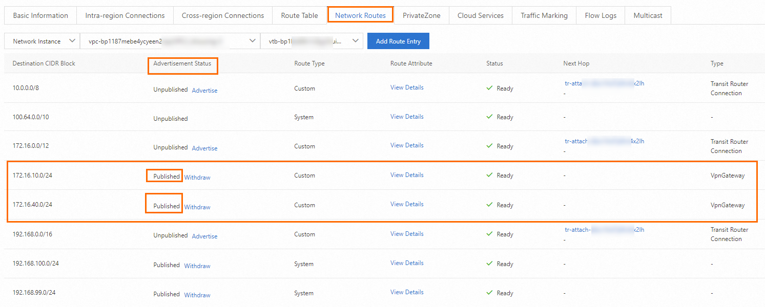
On the CEN details page, click the tab. Find the transit router in the China (Shanghai) region and click its ID.
On the details page, click the Network Routes tab.
On the Network Routes tab, find VPC1 and the routes that point to Data Center 1 and Data Center 2.
In the Advertisement Status column of the route, click Advertise. In the Advertise Route dialog box, confirm the route information and click OK.
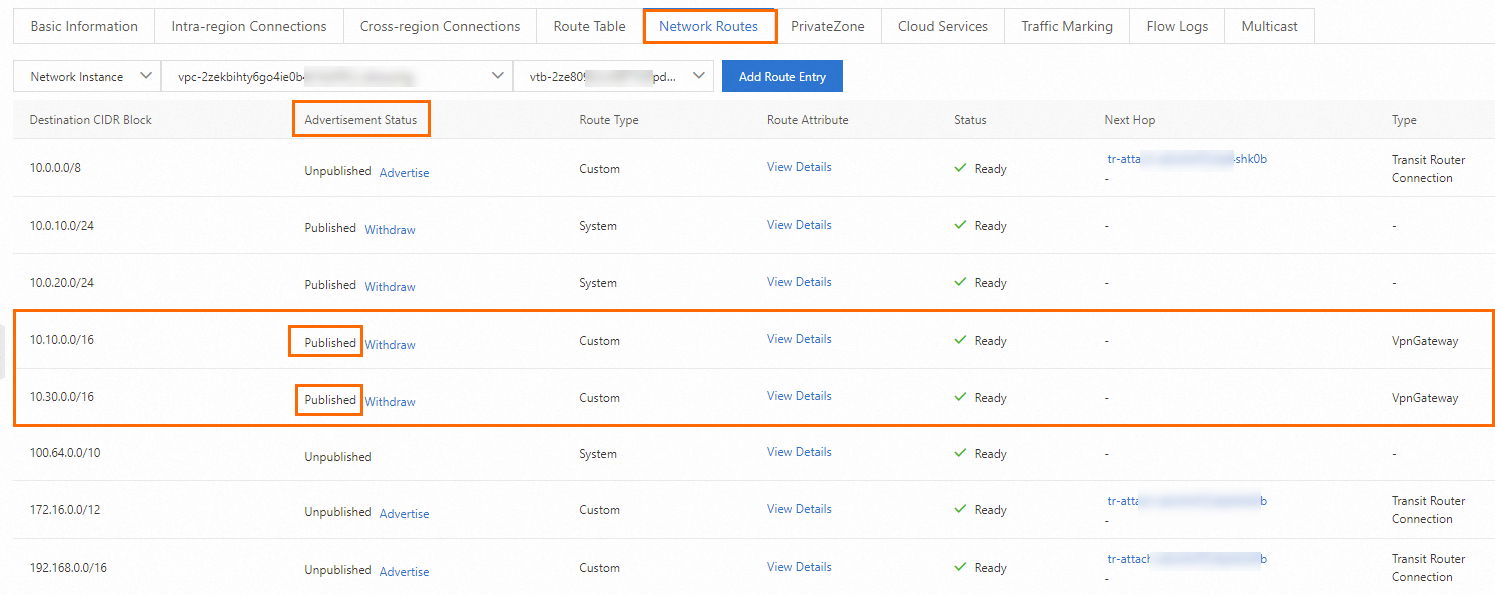
Repeat the preceding steps. Go to the details page of the transit router in the US (Silicon Valley) region. On VPC2, advertise the routes that point to Data Center 3 and Data Center 4 to the transit router.
Advertise routes of Data Center 1 and Data Center 2
Advertise routes of Data Center 3 and Data Center 4
Step 6: Test the connectivity
After you complete the preceding steps, the data centers and VPCs in different regions can communicate with each other. The following content describes how to test the network connectivity.
Before the test, make sure that you understand the security group rules applied to the ECS instance in the VPC and the ACL rules applied to the data center. Make sure that the rules allow mutual access between the VPC and the data center. For more information about ECS security group rules, see Query security group rules and Add security group rules.
Log on to ECS1 in VPC1. For more information, see Connection method overview.
Run the
pingcommand on ECS1 to access a client in another network.ping <the IP address of a client>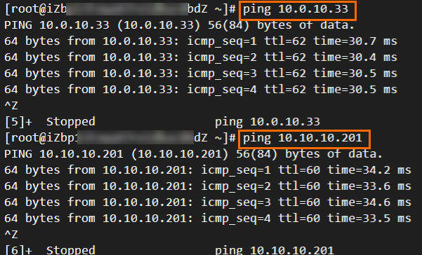
As shown in the preceding figure, if ECS1 can receive echo reply packets, it indicates that VPC1 can communicate with other networks.
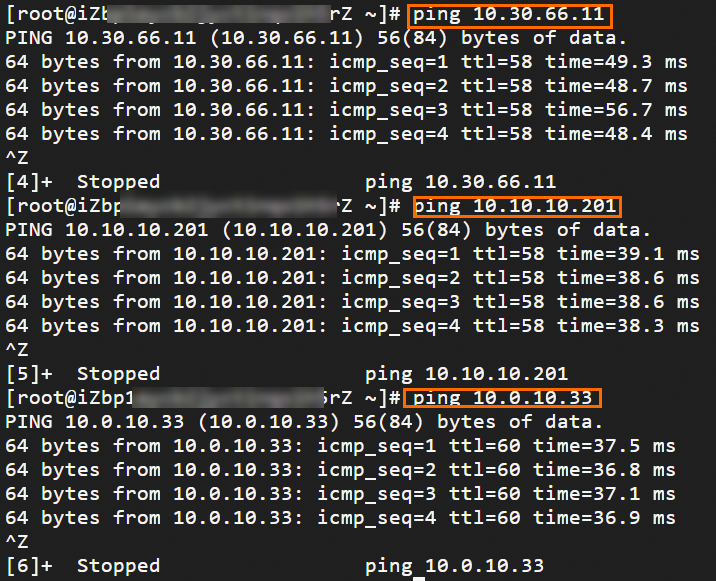
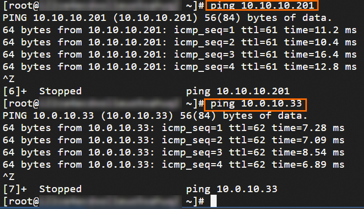
Log on to ECS2 in VPC2. For more information, see Connection method overview.
Run the
pingcommand on ECS2 to access a client in another network.ping <the IP address of a client>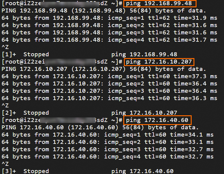
As shown in the preceding figure, if ECS2 can receive echo reply packets, it indicates that VPC2 can communicate with other networks.
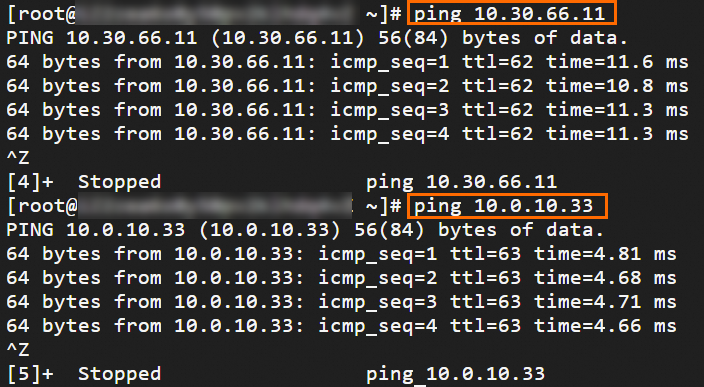
Open the CLI on a client in Data Center 1.
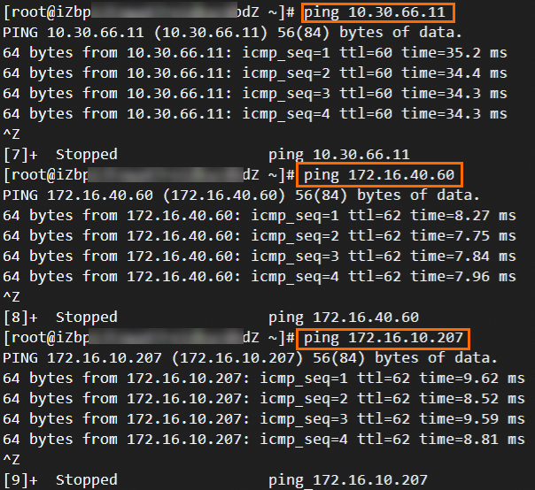
Run the
pingcommand to access a client in another network.ping <the IP address of a client>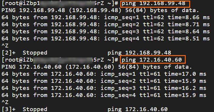
As shown in the preceding figure, if the client can receive echo reply packets, it indicates that Data Center 1 can communicate with other networks.
Open the CLI on a client in Data Center 2.
Run the
pingcommand to access a client in another network.ping <the IP address of a client>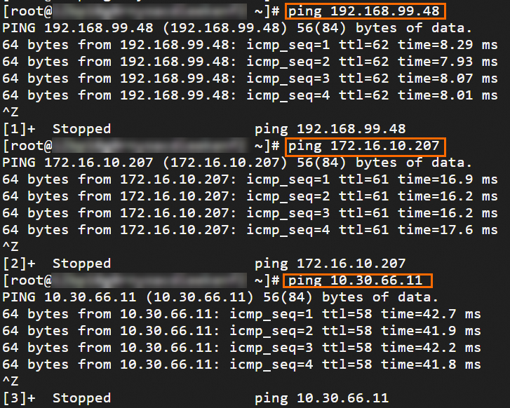
As shown in the preceding figure, if the client can receive echo reply packets, it indicates that Data Center 2 can communicate with other networks.
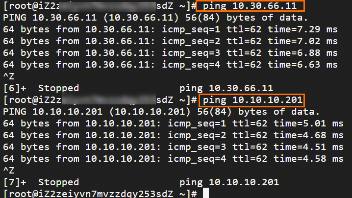
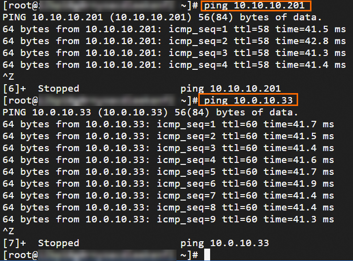
Open the CLI on a client in Data Center 3.
Run the
pingcommand to access a client in another network.ping <the IP address of a client>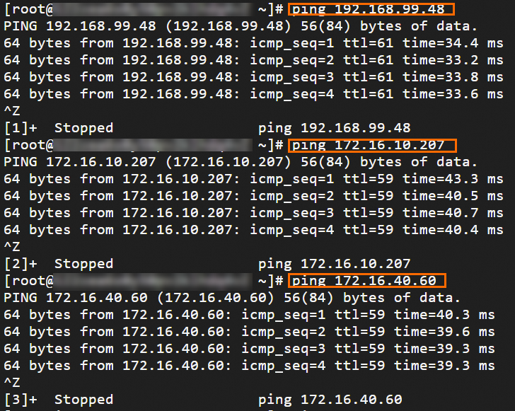
As shown in the preceding figure, if the client can receive echo reply packets, it indicates that Data Center 3 can communicate with other networks.
Open the CLI on a client in Data Center 4.
Run the
pingcommand to access a client in another network.ping <the IP address of a client>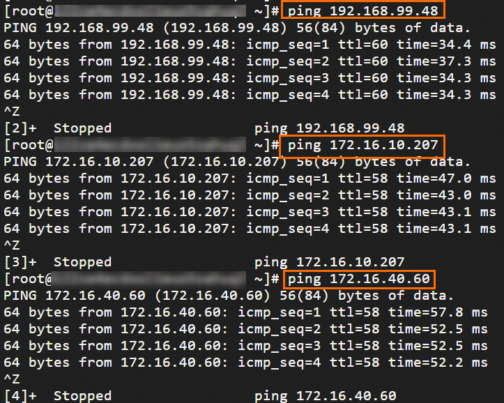
As shown in the preceding figure, if the client can receive echo reply packets, it indicates that Data Center 4 can communicate with other networks.