In order to win this inevitable battle and fight against COVID-19, we must work together and share our experiences around the world. Join us in the fight against the outbreak through the Global MediXchange for Combating COVID-19 (GMCC) program. Apply now at https://covid-19.alibabacloud.com/
By GXIC.
Non-contact infrared thermometers have been widely used in medical treatment, environmental monitoring, personal health, besides several other fields. This article will show you how to quickly complete body temperature detection by using the Wi-Fi module of AliOS Things Inside. The process covers sensor data collection, access to Link Living, and rapid app development for monitoring. With the complete solution from end devices to the cloud application provided by Alibaba Cloud's IoT Platform, smart device manufacturers can be empowered to build automated body temperature measurement devices and solutions, which can replace manpower, reducing personnel exposure risks in and improving screening efficiency.
Link Living provides device access capabilities, mobile client SDKs, and development-free public app and interfaces. With this platform, developers can quickly make devices smart devices.
Cloud Intelligence is a public app provided by Link Living. After you download the app, you can use it to perform network provisioning configuration and control your devices without additional development. You can search and download Cloud Intelligence in mainstream app stores around the world.
AliOS Things is a lightweight operating system for IoT. It supports a variety of chips, can easily integrate temperature sensors, and can connect to Link Living by using the device SDK. The latest version 3.0.0 is used here.
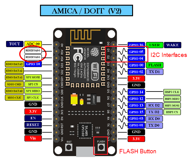
ESP8266 nodeMCU is used as the hardware platform, which supports Wi-Fi connectivity and provides interfaces, such as I2C and UART, and the FLASH button, which can be used to trigger body temperature detection and reporting.
This sensor is a non-contact infrared thermometer that supports the I2C communication protocol. It uses SDA and SCL lines which can be connected to ESP8266 development board.
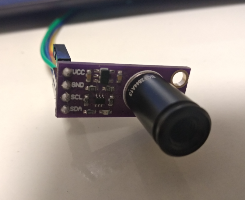
The specification is as follows:

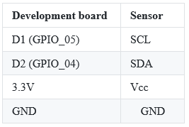
The following table shows the mapping of physical pins between the development board and the sensor.
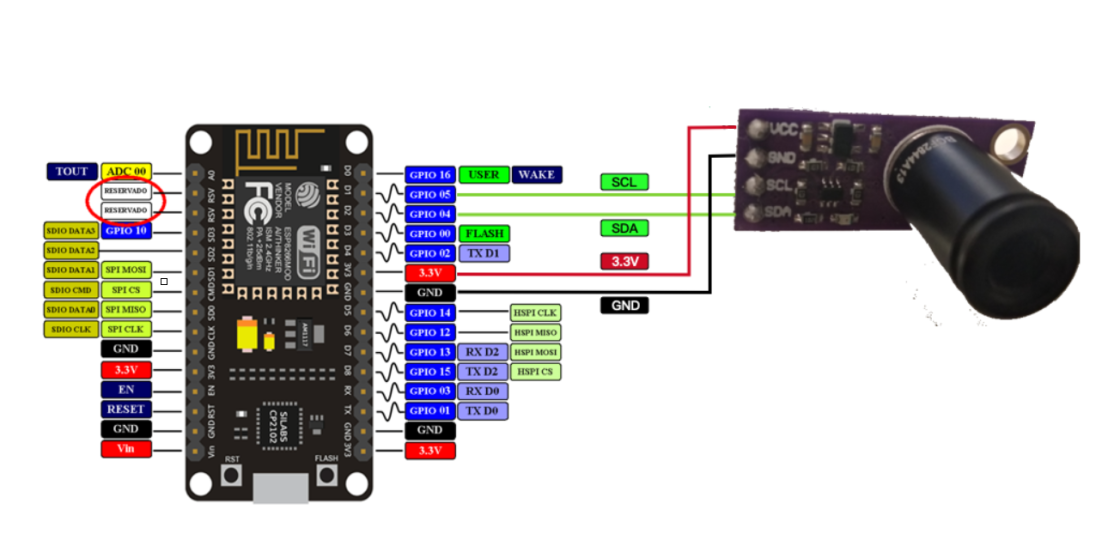
Hardware connection diagram
Before you create products and devices on Link Living, make sure you have made the following preparations:
You have created a project and a product on the console, and have defined the product features. When you define the product features, pay attention to the following two points:
1. You must select Thermometer from the Product Category drop-down list. The "Body Temperature" has been included in the standard features. You only need to modify the value range in data definition to 0 to 99.
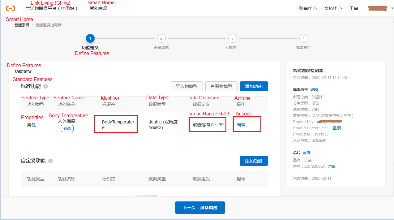
2. As shown in the preceding figure, the identifier used on the device for reporting the temperature should be consistent with that configured on the cloud, such as the identifier "Body Temperature" in the figure.
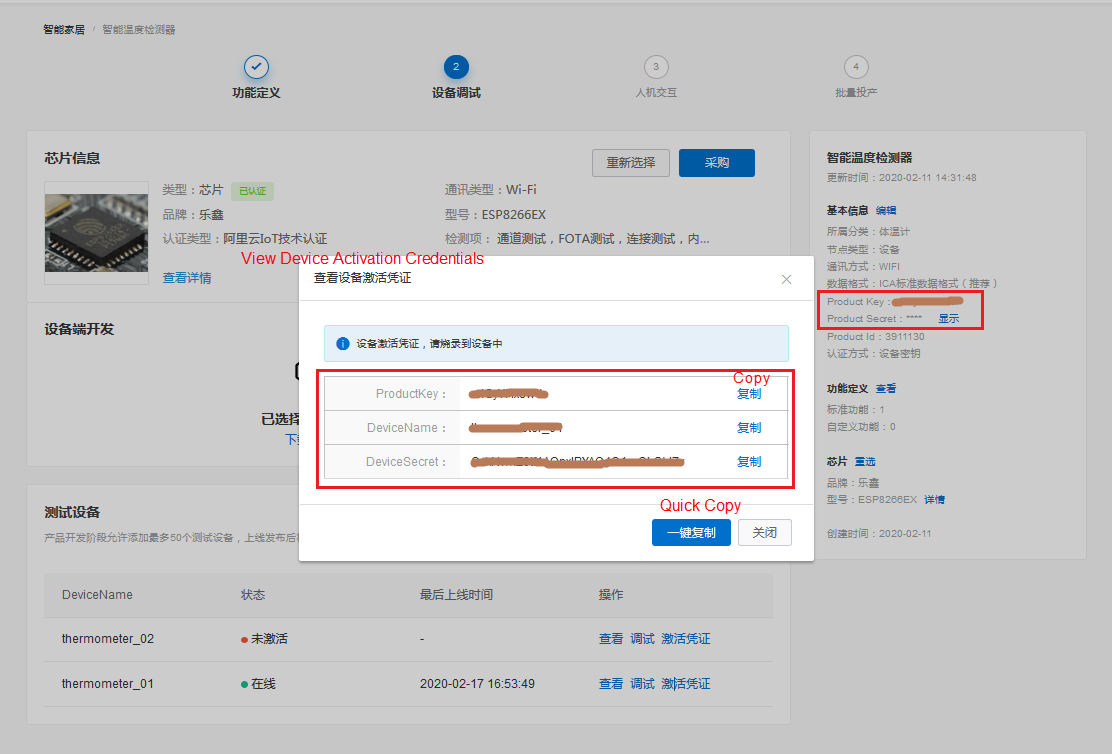
Add test devices, and record the credentials for device activation, which are ProductKey, ProductSecret, DeviceName, and DeviceSecret, as shown in the red box below. Configure the credentials on the device later.
The process for configuring parameters for Cloud Intelligence is as follows:
Get the Reference Code as shown in the following figure, and integrate as follows.

For the ESP8266 development board selected previously, to ensure the normal operation of button press interrupts, I2C, and other functions, the following modifications are required:
For specific modifications, see the patch file 001-aos-3-0-0-esp8266.patch in the attachment, which is generated based on AliOS Things version 3.0.0. Copy it to the root directory of AliOS Things 3.0.0 and run the following command to install the patch:
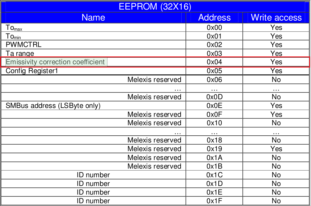
patch -p1 < ./001-aos-3-0-0-esp8266.patchMLX90614 is an infrared thermometer for non-contact temperature measurements. We will introduce its usage instructions. The EEPROM of MLX90614 is mainly used for parameter configuration. For more information, see the official manual.
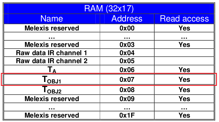
The RAM of MLX90614 is read-only. Users can read temperature and other data. For example, the temperature data of the detected object can be obtained through the Tobj1 on RAM.
The I2C bus accesses the sensor through the device address 0X5A (MLX90614 factory settings). The following table lists the mapping commands for RAM access and EEPROM access.

For example, to access the 0X4 address on EEPROM (Emissivity correction coefficient), you can obtain the operation code in the following way:
In the same way, the operation code for reading the temperature register (Tobj1) data of the detected object through RAM is 0X7.
The driver code located in drv_temp_melexis_mlx90614.c for reading the temperature of the detected object is as follows:
static int drv_temp_melexis_mlx90614_read(void *buf, size_t len)
{
    int                 ret = 0;
    size_t              size;
    uint8_t             data[2];
    int32_t             temp;
    uint32_t            value;
    temperature_data_t *pdata = (temperature_data_t *)buf;
    if (buf == NULL) {
        return -1;
    }

    size = sizeof(temperature_data_t);
    if (len < size) {
        return -1;
    }

    /* 通过I2C读取RAM上的Tobj寄存器
         MLX90614_ctx.config.dev_addr为设备地址0X5A
       MLX90614_TOBJ1为访问Tobj1的操作码0X07 */
    ret = hal_i2c_mem_read(&MLX90614_ctx, MLX90614_ctx.config.dev_addr, MLX90614_TOBJ1, I2C_REG_LEN, data,
                           2, I2C_OP_RETRIES);
    value = data[0] | (data[1]<<8);
    if (unlikely(ret)) {
        return -1;
    }
    /* 寄存器的值转换成温度数据,单位为0.01℃ */
    temp = ((int32_t)value * 2) - 27315;
    pdata->t = temp;
    pdata->timestamp = aos_now_ms();

    return (int)size;
}
The following describes how to integrate the driver. Copy the driver file drv_temp_melexis_mlx90614.c to the driverssensordrv directory, and add the compilation configuration on the first line of driverssensordrv.mk.
    ifeq ($(AOS_SENSOR_TEMP_MELEXIS_MLX90614),y)
    $(NAME)_SOURCES += drv/drv_temp_melexis_mlx90614.c
endifCopy the use case code (thermometer folder) to the app example directory, and add the case compilation configuration in appexampleConfig.in.
source "app/example/thermometer/Config.in"
if AOS_APP_THERMOMETER
    config AOS_BUILD_APP
        default "thermometer"
endif
The initialization process is as follows. For more information, see the entry function application_start.
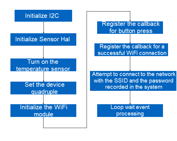
The button press interrupt-related code of ESP8266 is in mcuesp8266bspkey.c. After you press the button, the callback function will trigger different events through aos_post_event based on the pressing time (short press, long press for 2 seconds, and long press for 6 seconds). The callback function registered in application_start will respond to the aforementioned events. The code for the callback function is as follows:
/* 按键回调函数 */
void linkkit_key_process(input_event_t *eventinfo, void *priv_data)
{
    if (eventinfo->type != EV_KEY) {
        return;
    }

    if (eventinfo->code == CODE_BOOT) {
        if (eventinfo->value == VALUE_KEY_CLICK) {
            /* 短按(>40ms),触发一次体温检测,并上报云端 */
            app_sensor_test();
        } else if (eventinfo->value == VALUE_KEY_LTCLICK) {
            /* 长按(>2s), 触发系统进入配网模式 */
            do_awss_active();
        } else if (eventinfo->value == VALUE_KEY_LLTCLICK) {
            /* 长按(>6s),会清除配网信息,并复位系统 */
            do_awss_reset();
        }
    }
}
You can see the code for the detection and reporting processes of body temperature data, as shown in the following figure. If the temperature is lower than the normal body temperature range (34°C to 42°C [93.2°F to 107.6°F]), the reported data is 0. If the temperature is higher than the normal body temperature range, the reported data is 99.
/* 读取温度数据并上报云端 */
void app_sensor_test()
{
    int ret;
    char param[128];
    temperature_data_t temp;
    double data = 0.0;

    /* 读取温度传感器数据 */
    ret = sensor_hal_read(TAG_DEV_TEMP, 0, &temp, sizeof(temp));
    if(ret <= 0){
        printf("\nSensor data read fail \n");
        return;
    }

    data = (double)temp.t;
    data = data/100.0;

    /* 人体温度数据校准 */
    data = data - (data * data * data *data * data* data) * 0.000125 +
           (data * data * data *data * data) * 0.0283429488 -
           (data * data * data *data ) * 2.67004808 +
           (data * data * data ) * 133.762569 -
           (data * data ) * 3758.41829 +
           (data ) * 56155.4892 -
           348548.755;

    if (data < 34.0) {
        data = 0.0;
        printf("\nNot the normal range of human body temperature (34 ~ 42℃ ) \n");
    }
    else if (data > 42.0) {
        data = 99.0;
        printf("\nNot the normal range of human body temperature (34 ~ 42℃ ) \n");
    }

    /* 网络连接检测 */
    if (!app_conect_check()) {
        printf("\nNetwork is not connected\n");
        return;
    }

    memset(param, 0, 128);

    /* 构建上报云端的payload */
    sprintf(param, PROP_POST_FORMAT_TEMP, data);

    /* 上报体温数据到云端 */
    if (app_init_check() != 0) {
        ret = IOT_Linkkit_Report(app_device_get(), ITM_MSG_POST_PROPERTY, (unsigned char *)param, strlen(param) + 1);
        if (ret == -1) {
            LOG("%s %d fail\n", __func__,__LINE__);
        }
    }
}Update the device credentials (quadruple) recorded in Section 3.2 to app_entry.h under the directory of appexamplethermometer on the device.
#define PRODUCT_KEY    "xxxxxxxxxxx"
#define PRODUCT_SECRET "xxxxxxxxxxxxxxxx"
#define DEVICE_NAME    "xxxxxxxxxxxxxx"
#define DEVICE_SECRET "xxxxxxxxxxxxxxxxxxxxxxxxxxxxxxxx"Make sure that the identifier corresponding to the reported body temperature on the device (app_entry.h under the directory of appexamplethermometer) is consistent with the cloud configuration in Section 3.1.
#define PROP_POST_FORMAT_TEMP "{\"BodyTemperature\":%.1f}"1. Run the following command in the OS directory to complete the compilation.
2.
make thermometer@esp8266 -c config
aos make
3. The compiled firmware thermometer@esp8266.bin is in the outthermometer@esp8266binary directory.
4. Burn it by using FLASH_DOWNLOAD_TOOLS of ESP8266.
The development board is as follows:
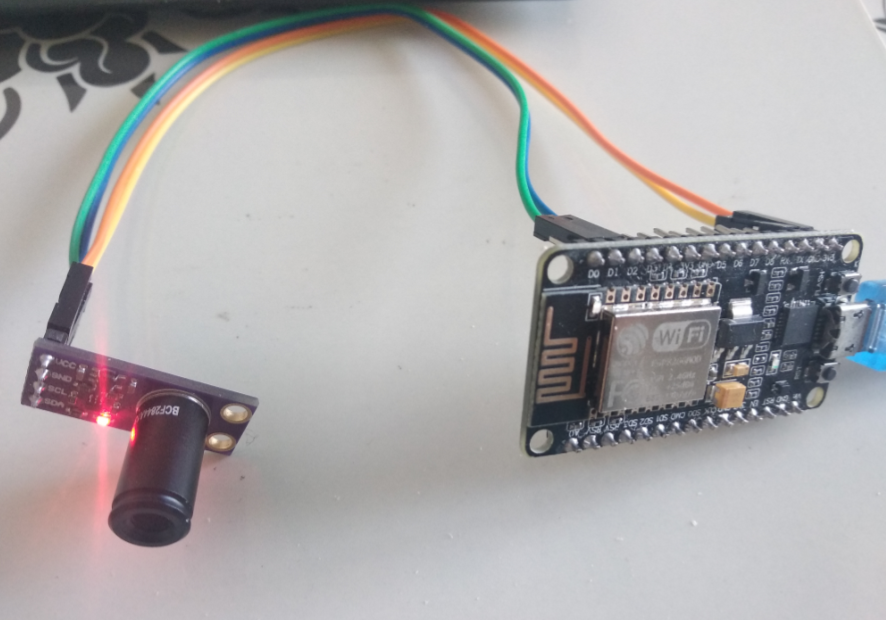
After the board is reset, long press the FLASH button more than 2 seconds to start the network configuration provisioning process.
After the network provisioning configuration is successful, short press the FLASH button (more than 40 milliseconds) to trigger a temperature collection, upload it to the cloud, and push it to Cloud Intelligence on the mobile.
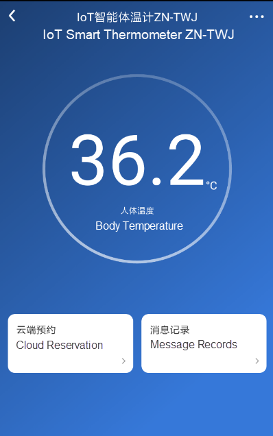
It should be noted that calibration has been added to the use case. The temperature range is 34℃ to 42℃ (93.2°F to 107.6°F). When the temperature is below this range, the reported data is 0. When the temperature is above this range, the reported data is 99.
While continuing to wage war against the worldwide outbreak, Alibaba Cloud will play its part and will do all it can to help others in their battles with the coronavirus. Learn how we can support your business continuity at https://www.alibabacloud.com/campaign/fight-coronavirus-covid-19
How Can Small Businesses Survive the COVID-19? Learn How Innovative Financial Models Can Help
Learn How the Industrial Internet is Helping Enterprises Get Back on Feet Faster

2,605 posts | 747 followers
FollowGXIC - November 2, 2018
Alibaba Clouder - May 24, 2018
Alibaba Clouder - August 6, 2019
Alibaba Clouder - March 16, 2021
GXIC - October 16, 2019
GXIC - June 11, 2019

2,605 posts | 747 followers
Follow IoT Platform
Provides secure and reliable communication between devices and the IoT Platform which allows you to manage a large number of devices on a single IoT Platform.
Learn More Platform For AI
A platform that provides enterprise-level data modeling services based on machine learning algorithms to quickly meet your needs for data-driven operations.
Learn MoreMore Posts by Alibaba Clouder