You can use a VPN Gateway to configure a dual-tunnel IPsec-VPN connection between a VPC and a data center. This prevents service disruptions if a single tunnel fails and ensures high connection availability.
How it works
A company creates a VPC in the Alibaba Cloud Singapore region with a primary CIDR block of 192.168.0.0/16 and deploys an on-premises data center in Singapore with a CIDR block of 172.16.0.0/16. Because of business growth, the on-premises data center needs to access resources in the VPC. The company can use VPN Gateway to establish an IPsec-VPN connection in dual-tunnel mode between the VPC and the on-premises data center.
The dual-tunnel mode includes an active tunnel and a standby tunnel. The system automatically detects the connectivity of the active tunnel. If the active tunnel is disconnected, the VPN Gateway automatically switches traffic to the standby tunnel. After the active tunnel recovers, traffic is automatically switched back.
When a VPN Gateway is created, it is assigned two public IP addresses to establish the active and standby tunnels. Each tunnel independently performs IKE negotiation, key exchange, and data transmission.
This topic uses the deployment of strongSwan software on an on-premises gateway device as an example. For more information, see Other on-premises gateway device configuration examples.

Applicable scope
On-premises gateway device:
The gateway device must have public IP addresses. We recommend that you configure two public IP addresses, or deploy two gateway devices in the data center, each with one public IP address.
The gateway device must support the IKEv1 or IKEv2 protocol.
VPC: The dual-tunnel mode for IPsec-VPN connections is supported in the following regions and zones.
The CIDR block of the data center does not overlap with the CIDR block of the VPC.
Procedure
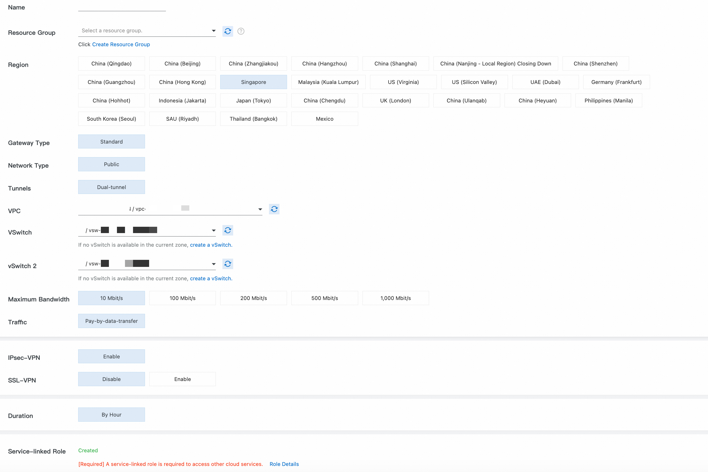
Step 1: Create a VPN gateway
Go to the or the VPN Gateway management console.
Instance Name, Resource Group: You can use these parameters together to identify cloud resources.
Region: Select the region where your VPC is located. In this topic, Singapore is used.
Gateway Type: Select Standard.
Network Type: Select Public.
Tunnel: Select Dual-tunnel.
Virtual Private Cloud (VPC): Select the VPC that you plan to connect to the local data center.
vSwitch 1, vSwitch 2: Select two vSwitches in different zones of the VPC.
Peak Bandwidth: Use the default value.
Traffic: Select Pay-By-Data-Transfer.
Enable IPsec-VPN, and disable SSL-VPN.
Subscription Duration: Use the default value.
Service-linked Role: Ensure that the service-linked role AliyunServiceRoleForVpn is created. VPN Gateway uses this role to access resources in other cloud products.
Return to the VPN Gateway page. The initial status of the VPN gateway instance is Preparing. After about 1 to 5 minutes, the status changes to Normal and the system assigns two public IP addresses to the VPN Gateway for an active tunnel and a standby tunnel. In this example, the assigned public IP addresses are:
120.XX.XX.152 (IPsec address 1 - active tunnel)and120.XX.XX.0 (IPsec address 2 - standby tunnel).
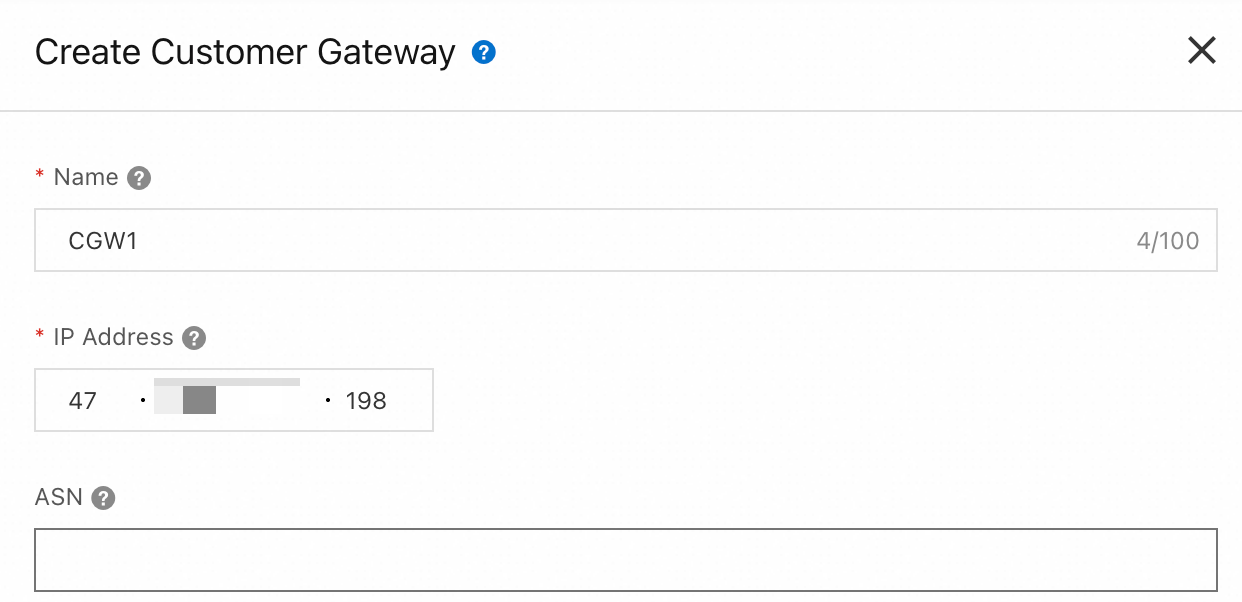
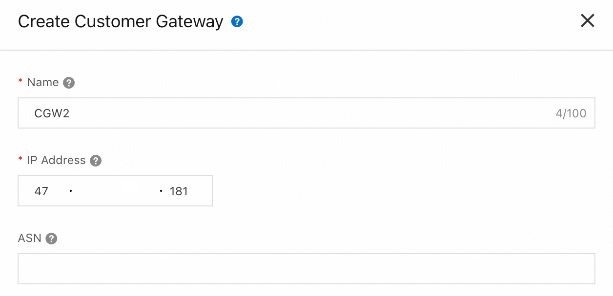
Step 2: Create a customer gateway
Go to VPN - Customer Gateway and click Create Customer Gateway.
Create two customer gateways to establish two encrypted tunnels.
|
|
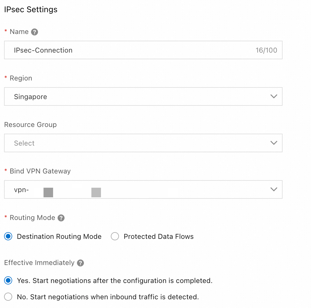
Step 3: Create an IPsec connection
Go to the VPN - Create IPsec-VPN Connection page, complete the configuration, and then click OK.
IPsec configuration
Region: Select the region where your VPC is located. In this topic, Singapore is used.
Attach VPN Gateway: Select the VPN Gateway that you created in Step 1.
Routing Mode: Select Destination-based Route to route and forward traffic based on the destination IP address.
Effective Immediately: Select Yes. Negotiation starts immediately after the configuration is complete.
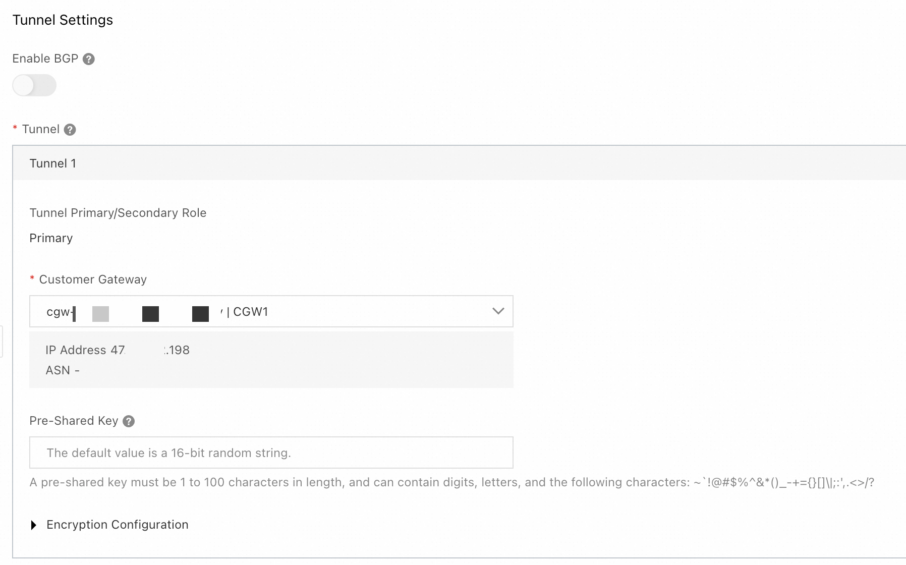
Tunnel configuration
Enable BGP: In this example, this feature is not enabled.
Tunnel: Configure the active and standby tunnels.
Tunnel 1 is the primary tunnel.
Customer Gateway: Select the customer gateway
CGW1that you created in Step 2.Pre-shared Key: The pre-shared key of the tunnel must be the same as that of the peer gateway device. Otherwise, the IPsec-VPN connection cannot be established.
Encryption Configuration: Select the encryption configuration based on the support of the on-premises gateway device. Make sure that the encryption configuration of the IPsec connection is the same as that of the on-premises gateway device.
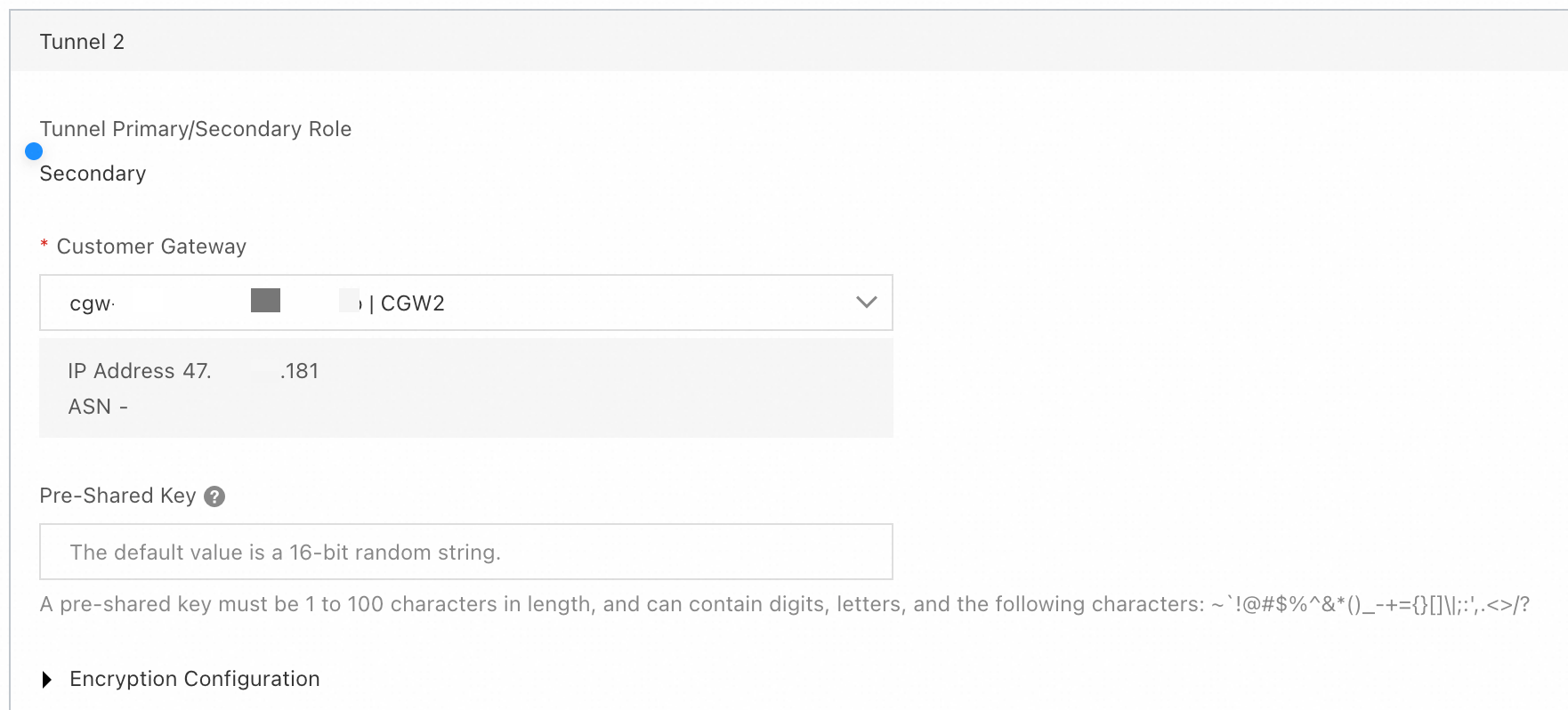
Tunnel 2: Standby tunnel.
Customer Gateway: Select the customer gateway
CGW2that you created in Step 2.Pre-shared Key: Use the same configuration as the active tunnel. The pre-shared key of the tunnel must be the same as that of the peer gateway device. Otherwise, the IPsec-VPN connection cannot be established.
Encryption Configuration: Select the encryption configuration based on the support of the on-premises gateway device. Make sure that the encryption configuration of the IPsec connection is the same as that of the on-premises gateway device.
In the Created dialog box, click Cancel. Find the created IPsec connection and click Generate Peer Configuration in the Actions column. Click Copy and save the configuration to your on-premises device. You will need this configuration to configure the on-premises gateway device.
Step 4: Configure the on-premises gateway device
This topic uses an on-premises gateway device that runs strongSwan software (a strongSwan device) as an example.
Other on-premises gateway device configuration examples.
The following content contains third-party product information for reference only. Alibaba Cloud does not make any warranties, express or implied, with respect to the performance and reliability of third-party products, or the potential impact of operations that are performed using these products.
The following steps use a strongSwan device that runs the CentOS Stream 9 64-bit operating system as an example. For other operating systems, see the official strongSwan documentation.On the strongSwan device, update the firewall policy to allow traffic on the ESP protocol (IP protocol number 50), UDP port 500, and UDP port 4500.
iptables -I INPUT -p 50 -j ACCEPT
iptables -I INPUT -p udp --dport 500 -j ACCEPT
iptables -I INPUT -p udp --dport 4500 -j ACCEPT
Run
echo 1 > /proc/sys/net/ipv4/ip_forwardto enable traffic forwarding.Run
dnf install epel-release -yanddnf install strongswan -yto install the strongSwan software.Configure dual tunnels:
Dual-egress is implemented based on XFRM virtual network interfaces. To use XFRM virtual network interfaces, you must install strongSwan 5.8.0 or later. In addition, the Linux kernel version must be 4.19 or later, the iproute2 version must be 5.1.0 or later, and the kernel must support the xfrm module. The module is not supported if the
lsmod | grep xfrmcommand returns an empty result. For more information, see XFRM Interfaces on Linux.Add routes that point to the two Alibaba Cloud IPsec addresses. This allows IPsec address 1 to be accessed through the eth0 egress and IPsec address 2 to be accessed through the eth1 egress. Verify that you can ping the IPsec addresses.
ip route add 120.XX.XX.152 via 172.16.1.253 dev eth0  #172.16.1.253 is the private gateway address of eth0
ip route add 120.XX.XX.0 via 172.16.2.253 dev eth1   #172.16.2.253 is the private gateway address of eth1
Create two virtual network interfaces to establish the active and standby IPsec-VPN tunnels.
ip link add ipsec0 type xfrm dev eth0 if_id 42 # Create an XFRM virtual network interface for tunnel 1. The interface ID is 42 and the underlying interface is the public interface eth0. ip link add ipsec1 type xfrm dev eth1 if_id 43 # Create an XFRM virtual network interface for tunnel 2. The interface ID is 43 and the underlying interface is the public interface eth1. ip link set ipsec0 up # Start the XFRM virtual network interface for tunnel 1. ip link set ipsec1 up # Start the XFRM virtual network interface for tunnel 2.Modify the strongSwan configuration file.
Run
mv /etc/strongswan/swanctl/swanctl.conf /etc/strongswan/swanctl/swanctl.conf.bakto back up the original configuration file.Run
vi /etc/strongswan/swanctl/swanctl.conf. Add the following configuration to the file and save it. Modify the parameters based on the IPsec-VPN connection configuration.connections { vco1 { # Add the VPN configuration for IPsec-VPN tunnel 1 version = 2 # Specifies the IKE version. It must be the same as the IKE version of tunnel 1 on the Alibaba Cloud side. 2 indicates IKEv2. local_addrs = 172.16.0.93 # The IP address of the first on-premises network interface card. remote_addrs = 120.XX.XX.152 # Specifies the peer IP address for tunnel 1, which is the gateway IP address of tunnel 1 on the Alibaba Cloud side (IPsec address 1). dpd_delay = 10 rekey_time = 84600 # Specifies the security association lifetime for tunnel 1. It must be the same as the SA lifetime in the IKE configuration of tunnel 1 on the Alibaba Cloud side. over_time = 1800 proposals = aes-sha1-modp1024 # Specifies the encryption algorithm, authentication algorithm, and DH group for tunnel 1. It must be the same as the IKE configuration of tunnel 1 on the Alibaba Cloud side. group2 corresponds to modp1024. encap = yes local { auth = psk # The local authentication method is PSK, which uses a pre-shared key. id = 47.XX.XX.198 # The first on-premises public egress IP address. It must be the same as the RemoteId of tunnel 1 on the Alibaba Cloud side. } remote { auth = psk # The remote authentication method is PSK, which means Alibaba Cloud uses a pre-shared key. id = 120.XX.XX.152 # IPsec address 1 on the Alibaba Cloud side. It must be the same as the LocalId of tunnel 1 on the Alibaba Cloud side. } children { vco_child1 { local_ts = 0.0.0.0/0 remote_ts = 0.0.0.0/0 mode = tunnel rekey_time = 85500 life_time = 86400 # Specifies the SA lifetime for tunnel 1. It must be the same as the SA lifetime in the IPsec configuration of tunnel 1 on the Alibaba Cloud side. dpd_action = restart start_action = start close_action = start esp_proposals = aes-sha1-modp1024 # Specifies the encryption algorithm, authentication algorithm, and DH group for tunnel 1. It must be the same as the IPsec configuration of tunnel 1 on the Alibaba Cloud side. group2 corresponds to modp1024. if_id_out = 42 # Specifies the outbound and inbound interfaces for tunnel 1 as the XFRM virtual network interface for tunnel 1. if_id_in = 42 updown = /root/connect_1.sh # Executes the /root/connect_1.sh script based on the UP and DOWN status of tunnel 1 to configure routes. } } } vco2 { # Add the VPN configuration for IPsec-VPN tunnel 2 version = 2 # Specifies the IKE version. It must be the same as the IKE version of tunnel 2 on the Alibaba Cloud side. 2 indicates IKEv2. local_addrs = 172.16.2.57 # The IP address of the second on-premises network interface card. remote_addrs = 120.XX.XX.0 # Specifies the peer IP address for tunnel 2, which is the gateway IP address of tunnel 2 on the Alibaba Cloud side (IPsec address 2). dpd_delay = 10 rekey_time = 84600 # Specifies the SA lifetime for tunnel 2. It must be the same as the SA lifetime in the IKE configuration of tunnel 2 on the Alibaba Cloud side. over_time = 1800 proposals = aes-sha1-modp1024 # Specifies the encryption algorithm, authentication algorithm, and DH group for tunnel 2. It must be the same as the IKE configuration of tunnel 2 on the Alibaba Cloud side. group2 corresponds to modp1024. encap = yes local { auth = psk # The local authentication method is PSK, which uses a pre-shared key. id = 47.XX.XX.181 # The second on-premises public egress IP address. It must be the same as the RemoteId of tunnel 2 on the Alibaba Cloud side. } remote { auth = psk # The remote authentication method is PSK, which means Alibaba Cloud uses a pre-shared key. id = 120.XX.XX.0 # IPsec address 2 on the Alibaba Cloud side. It must be the same as the LocalId of tunnel 2 on the Alibaba Cloud side. } children { vco_child2 { local_ts = 0.0.0.0/0 remote_ts = 0.0.0.0/0 mode = tunnel rekey_time = 85500 life_time = 86400 # Specifies the SA lifetime for tunnel 2. It must be the same as the SA lifetime in the IPsec configuration of tunnel 1 on the Alibaba Cloud side. dpd_action = restart start_action = start close_action = start esp_proposals = aes-sha1-modp1024 # Specifies the encryption algorithm, authentication algorithm, and DH group for tunnel 2. It must be the same as the IPsec configuration of tunnel 2 on the Alibaba Cloud side. group2 corresponds to modp1024. if_id_out = 43 # Specifies the outbound and inbound interfaces for tunnel 2 as the XFRM virtual network interface for tunnel 2. if_id_in = 43 updown = /root/connect_2.sh # Executes the /root/connect_2.sh script based on the UP and DOWN status of tunnel 2 to configure routes. } } } } # The key configuration here does not specify an ID and is shared by all tunnels. If you do not specify an ID, make sure the two keys are identical. Otherwise, negotiation may fail. secrets { ike-vco1 { secret = <Specify the pre-shared key for tunnel 1> # Must be the same as the pre-shared key of tunnel 1 on the Alibaba Cloud side. } ike-vco2 { secret = <Specify the pre-shared key for tunnel 2> # Must be the same as the pre-shared key of tunnel 2 on the Alibaba Cloud side. } }
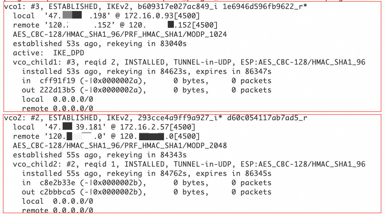
Restart the strongSwan process, reload the strongSwan configuration, and check the tunnel status.
sudo systemctl restart strongswan
swanctl --load-all
watch swanctl --list-sas
As shown in the following figure, an IPsec-VPN connection is established between the strongSwan device and the VPN gateway.
Configure routes:
Run
vi /root/connect_1.sh, and then add and save the following configuration.# If tunnel 1 is UP, add a route to direct traffic from the data center to the Alibaba Cloud VPC (192.168.0.0/16) through the ipsec0 XFRM virtual network interface. # Set the metric value of this route to 100 to give it a higher priority than the route to the ipsec1 XFRM virtual network interface. # If tunnel 1 is DOWN, delete this route. #!/usr/bin/env bash if [ x"$PLUTO_VERB" == "xup-client" ]; then echo "ip route add 192.168.0.0/16 dev ipsec0" >> /root/vpn_route.log;ip route add 192.168.0.0/16 dev ipsec0 metric 100 elif [ x"$PLUTO_VERB" == "xdown-client" ]; then echo "ip route del 192.168.0.0/16 dev ipsec0" >> /root/vpn_route.log;ip route del 192.168.0.0/16 dev ipsec0 metric 100 fiRun
vi /root/connect_2.sh, and then add and save the following configuration.# If tunnel 2 is UP, add a route to direct traffic from the data center to the Alibaba Cloud VPC (192.168.0.0/16) through the ipsec1 XFRM virtual network interface. # Set the metric value of this route to 101 to give it a lower priority than the route to the ipsec0 XFRM virtual network interface. # If tunnel 2 is DOWN, delete this route. #!/usr/bin/env bash if [ x"$PLUTO_VERB" == "xup-client" ]; then echo "ip route add 192.168.0.0/16 dev ipsec1" >> /root/vpn_route.log;ip route add 192.168.0.0/16 dev ipsec1 metric 101 elif [ x"$PLUTO_VERB" == "xdown-client" ]; then echo "ip route del 192.168.0.0/16 dev ipsec1" >> /root/vpn_route.log;ip route del 192.168.0.0/16 dev ipsec1 metric 101 fiRun
sudo chmod +x /root/connect_1.shandsudo chmod +x /root/connect_2.shto grant executable permissions.Run
sudo systemctl restart strongswanto restart the strongSwan process.Run
route -nto confirm that the routes are configured.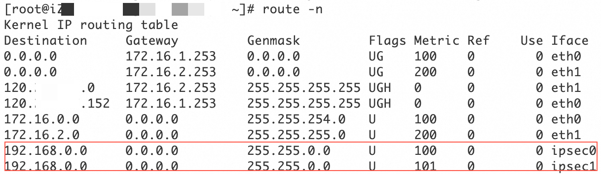
On the servers in the data center that need to connect to the VPC, configure a route that has the VPC CIDR block as the destination CIDR block and the strongSwan device as the next hop.
Run the following commands to disable rp_filter to prevent connectivity issues caused by asymmetric routing.
sudo sysctl -w net.ipv4.conf.all.rp_filter=0
sudo sysctl -w net.ipv4.conf.eth0.rp_filter=0
sudo sysctl -w net.ipv4.conf.eth1.rp_filter=0
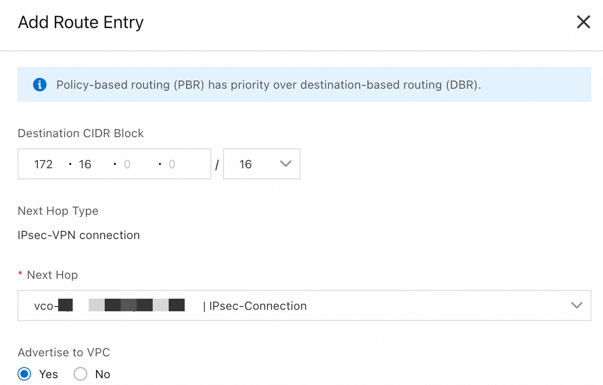
Step 5: Configure VPN Gateway routes
Go to the VPN - VPN Gateway page, and click the ID of the VPN gateway that you created in Step 1.
Click the Destination-based Route Table tab and click Add Route Entry.
|
|
Verification test
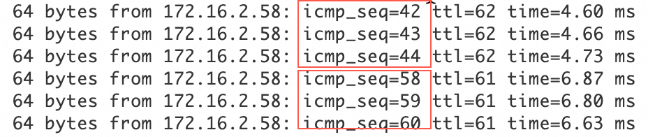
Test the connectivity between the data center and the VPC. To do this, log on to an ECS instance in the VPC and run the
ping <private IP address of a server in the data center>command. If you receive a reply message from the server in the data center, the connection is established.Test the high availability of the IPsec-VPN connection.
Log on to an ECS instance in the VPC. Run the
ping <private IP address of a server in the data center> -c 10000command to continuously send ping requests to the data center.Disconnect the active tunnel of the IPsec-VPN connection. You can do this by modifying the pre-shared key of the active tunnel. The tunnel disconnects because the pre-shared keys at the two ends of the tunnel no longer match.
After the active tunnel is disconnected, check the communication status of the ECS instance in the VPC. If traffic is briefly interrupted and then resumes, this indicates that traffic is automatically switched to the standby tunnel.