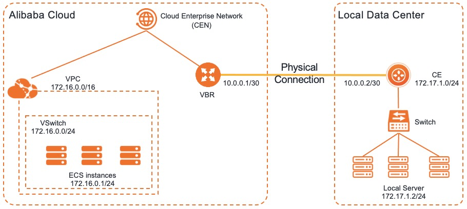
You can enable Border Gateway Protocol (BGP) on the network device in a data center and configure Bidirectional Forwarding Detection (BFD) on the virtual border router (VBR) to accelerate route convergence between the data center and a virtual private cloud (VPC).
Scenario
The following example shows how to configure BGP and BFD to accelerate route convergence. An enterprise has a data center in Hangzhou and creates a VPC in the China (Hangzhou) region. The enterprise wants to use an Express Connect circuit to connect a customer edge (CE) router to a VBR and use Cloud Enterprise Network (CEN) to enable communication between the data center and the VPC. To accelerate route convergence, the enterprise wants to configure BGP and BFD on the router in the data center and the VBR. This improves network availability.

Prerequisites
- The data center is connected to Alibaba Cloud by using an Express Connect circuit. For more information, see Connect a data center to ECS by using an Express Connect circuit.
- A BGP connection is established between the data center and the VPC. The BGP peer is in the Established state. For more information, see Configure and manage BGP.
Step 1: Configure BFD on the VBR
- Log on to the Express Connect console.
- In the top navigation bar, select a region and then click Virtual Border Routers (VBRs) in the left-side navigation pane.
- On the Virtual Border Routers (VBRs) page, find the VBR that you want to manage and click Edit in the Actions column.
- In the Edit VBR panel, set the BFD parameters and click OK. In this example, Submission Interval is set to 1000 milliseconds, Reception Interval is set to 1000 milliseconds, and Detection Time Multiplier is set to 3. These are the default values.
- Enable BFD.
Step 2: Configure BFD between the CE router and the VBR
- Log on to the CE router and run the following command to configure BFD:
System-view
Bgp <Autonomous System Number (ASN) of the CE router>
Peer <IP address of the VBR> bfd
Note In this example, 10.101.1.2 is used as the IP address of the VBR. - To verify the BFD configurations, run the
display bfd session verbosecommand.The following information is returned. Session State: Up indicates that a BGP connection is established between the CE router and the VBR and that BFD is enabled.
<CE> display bfd session verbose Total Session Num: 1 Up Session Num: 1 Init Mode: Active IPv4 Session Working Under Ctrl Mode: Local Discr: 513 Remote Discr: 513 Source IP: 10.101.1.1 Destination IP: 10.101.1.2 Session State: Up Interface: N/A Min Tx Inter: 500ms Act Tx Inter: 500ms Min Rx Inter: 500ms Detect Inter: 2500ms Rx Count: 135 Tx Count: 135 Connect Type: Indirect Running Up for: 00:00:58 Hold Time: 2457ms Auth mode: None Detect Mode: Async Slot: 0 Protocol: BGP Version:1 Diag Info: No Diagnostic - If multiple connections over Express Connect circuits are established between the data center and the VPC, repeat the preceding operations.
FAQ
- Can I configure BFD on one VBR to accelerate route convergence when two VBRs are attached to a CEN instance?
Yes, you can configure BFD on one VBR to accelerate route convergence when two VBRs are attached to a CEN instance.
- If BFD detects failures on one of two VBRs attached to a CEN instance, can the other VBR immediately take over?
Yes, the other VBR can immediately take over only if the two VBRs are added to a failover group. For more information about failover groups, see Configure a failover group.