This topic shows how to use IPsec-VPN in dual-tunnel mode to create a secure connection between two virtual private clouds (VPCs), allowing the resources in both VPCs to communicate.
Scenario
Cross-region IPsec-VPN connection quality depends on the public network. For more reliable connectivity, use Cloud Enterprise Network (CEN). See Connect VPCs across accounts.
An enterprise runs services on ECS instances in two VPCs (VPC1 and VPC2) in the Germany (Frankfurt) region. The services in VPC1 and VPC2 need to communicate with each other.
The enterprise uses VPN Gateway to establish an IPsec-VPN connection between the two VPCs, encrypting data in transit and enabling secure cross-VPC access.
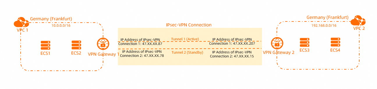
CIDR block planning
Plan the CIDR blocks based on your business requirements. Ensure that the CIDR blocks of the VPCs you connect do not overlap.
VPC CIDR blocks
VPC name | VPC CIDR block | ECS IP address |
VPC1 |
|
|
VPC2 |
|
|
IPsec-VPN BGP configuration
You can connect VPCs by using an IPsec-VPN connection with either static routes or BGP dynamic routing. The following table lists the BGP configurations required for this example.
If an IPsec-VPN connection uses BGP dynamic routing, the Local ASN for both tunnels must be the same. Although the peer BGP ASNs for the two tunnels can differ, using the same peer BGP ASN for both is recommended.
VPN gateway name | IPsec connection name | Tunnel | Local ASN | BGP tunnel CIDR block | BGP IP address |
VPN Gateway 1 | IPsec-VPN Connection 1 | Active tunnel | 65530 | 169.254.10.0/30 | 169.254.10.1 |
Standby tunnel | 65530 | 169.254.20.0/30 | 169.254.20.1 | ||
VPN Gateway 2 | IPsec-VPN Connection 2 | Active tunnel | 65500 | 169.254.10.0/30 | 169.254.10.2 |
Standby tunnel | 65500 | 169.254.20.0/30 | 169.254.20.2 |
Before you begin
The dual-tunnel mode for IPsec-VPN connections is available only in the following regions and availability zones.
You have created VPC1 and VPC2 in the Germany (Frankfurt) region, and deployed services on ECS instances within these VPCs. See Create a VPC with an IPv4 CIDR block.
You have verified that the security group rules for the ECS instances in both VPCs allow them to communicate with each other. See Query security group rules and Add a security group rule.
Configuration

Step 1: Create VPN gateway instances
Log on to the VPN Gateway console.
In the top navigation bar, select the region in which you want to create the VPN Gateway instance.
This example uses Germany (Frankfurt).
NoteThe VPN Gateway instance and the VPC instance must be in the same region to be associated.
On the VPN Gateways page, click Create VPN Gateway.
On the buy page, configure the VPN Gateway instance with the following settings, then click Buy Now and complete the payment.
Parameter
Description
Instance Name
Enter a name for the VPN Gateway instance. This example uses VPN Gateway 1.
Resource group
Select the resource group for the VPN Gateway instance. In this example, the default resource group is selected.
If you do not select a resource group, the system automatically assigns the VPN Gateway instance to the default resource group.
Region
Select the region in which you want to create the VPN Gateway instance. This example uses Germany (Frankfurt).
Gateway Type
Select the gateway type for the VPN Gateway instance. This example uses Standard.
Network type
Select the network type of the VPN Gateway instance. This example uses Public.
Tunnel
By default, Dual-tunnel is selected.
VPC
Select the VPC to associate with the VPN Gateway instance. This example uses VPC1.
vSwitch
Select the first vSwitch in VPC1.
If you select Single-tunnel, you need to specify only one vSwitch.
If you select Dual-tunnel, you need to specify two vSwitches.
After the IPsec-VPN feature is enabled, the system creates an elastic network interface (ENI) for each of the two vSwitches as an interface to communicate with the VPC over an IPsec-VPN connection. Each ENI occupies one IP address in the vSwitch.
NoteThe system selects a vSwitch by default. You can change or use the default vSwitch.
After a VPN gateway is created, you cannot modify the vSwitch associated with the VPN gateway. You can view the vSwitch associated with the VPN gateway, the zone to which the vSwitch belongs, and the ENI in the vSwitch on the details page of the VPN gateway.
vSwitch 2
Select the second vSwitch in VPC1.
Specify two vSwitches in different zones in the associated VPC to implement disaster recovery across zones for IPsec-VPN connections.
For a region that supports only one zone, disaster recovery across zones is not supported. We recommend that you specify two vSwitches in the zone to implement high availability of IPsec-VPN connections. You can also select the same vSwitch as the first one.
Maximum bandwidth
Select the public maximum bandwidth for the VPN Gateway instance. Unit: Mbps.
Traffic
The billing method for the VPN Gateway instance. The default value is Pay By Traffic.
See Billing.
IPsec-VPN
Enables or disables the IPsec-VPN feature. This example uses Enable.
SSL-VPN
Enables or disables the SSL-VPN feature. This example uses Close.
Billing cycle
The billing cycle of the VPN Gateway instance. The default value is By Hour.
Create Service-Linked Role
Click Create Service-Linked Role. The system automatically creates the AliyunServiceRoleForVpn service-linked role.
VPN Gateway uses this role to access resources in other cloud services. See AliyunServiceRoleForVpn.
If Created is displayed, the role already exists in your account and no action is required.
Return to the VPN Gateway page to view the new VPN Gateway instance.
A new VPN Gateway instance has an initial status of Preparing. After about 1 to 5 minutes, the status changes to Normal. A VPN Gateway instance with a Normal status is ready to use.
Repeat Step 3 to Step 4 to create another VPN Gateway instance named VPN Gateway 2 in the Germany (Frankfurt) region. Associate it with VPC2 and use the same settings as for VPN Gateway 1.
After the VPN Gateway instances are created, the following table describes their configurations.
Instance name
Associated VPC
IP address
VPN Gateway 1
VPC1
IPsec address 1: 47.XX.XX.87
IPsec address 2: 47.XX.XX.78
VPN Gateway 2
VPC2
IPsec address 1: 47.XX.XX.207
IPsec address 2: 47.XX.XX.15
Step 2: Create customer gateways
In the navigation pane on the left, choose .
In the top navigation bar, select the region where you want to create the customer gateway instances.
NoteThe customer gateway and VPN gateway instances must be in the same region to connect.
On the Customer Gateway page, click Create Customer Gateway.
In the Create Customer Gateway panel, configure the customer gateway instances as described in the following table, and then click OK.
Create four customer gateways in the Germany (Frankfurt) region for the VPN tunnels. The following table describes the required parameters. For all other parameters, keep the default values.
Parameter
Description
Germany (Frankfurt)
Germany (Frankfurt)
Germany (Frankfurt)
Germany (Frankfurt)
Name
Enter a name for the customer gateway instance.
VPN Gateway 1-Customer1
VPN Gateway 1-Customer2
VPN Gateway 2-Customer1
VPN Gateway 2-Customer2
IP Address
Enter the IP address of the peer VPN gateway instance.
NoteIn this scenario, each VPN gateway acts as the customer gateway for the other.
IP address for IPsec address 1 of VPN Gateway 2: 47.XX.XX.207.
IP address for IPsec address 2 of VPN Gateway 2: 47.XX.XX.15.
IP address for IPsec address 1 of VPN Gateway 1: 47.XX.XX.87.
IP address for IPsec address 2 of VPN Gateway 1: 47.XX.XX.78.
ASN
Enter the BGP ASN of the peer VPN gateway instance.
BGP ASN for the active tunnel of VPN Gateway 2: 65500.
BGP ASN for the standby tunnel of VPN Gateway 2: 65500.
BGP ASN for the active tunnel of VPN Gateway 1: 65530.
BGP ASN for the standby tunnel of VPN Gateway 1: 65530.
Step 3: Create IPsec-VPN connections
After you create the VPN gateways and customer gateways, create two IPsec-VPN connections to establish the encrypted tunnel.
In the left navigation pane, choose .
On the IPsec Connections page, click Bind VPN Gateway, configure the IPsec connection as follows, and then click OK.
Create two IPsec connections in the Germany (Frankfurt) region using the settings in the following table.
Parameter
Description
IPsec Connection 1
IPsec Connection 2
Name
Enter a name for the IPsec connection.
For this tutorial, enter IPsec Connection 1.
For this tutorial, enter IPsec Connection 2.
Region
Select the region where the VPN gateway to be associated with the IPsec-VPN connection is deployed.
The IPsec-VPN connection is created in the same region as the VPN gateway.
Select Germany (Frankfurt).
Select Germany (Frankfurt).
Bind VPN Gateway
Select the VPN gateway to associate with the IPsec-VPN connection.
For this tutorial, select VPN Gateway 1.
For this tutorial, select VPN Gateway 2.
Routing Mode
Select a routing mode.
NoteIf you plan to use BGP for the IPsec-VPN connection, select Destination Routing Mode.
For this tutorial, select Destination Routing Mode.
For this tutorial, select Destination Routing Mode.
Effective Immediately
Determines whether the IPsec connection takes effect immediately.
Yes. Start negotiations after the configuration is completed.
No. Start negotiations when inbound traffic is detected.
NoteWhen connecting two VPCs with a VPN gateway, set Effective Immediately to Yes for one of the IPsec-VPN connections. This starts IPsec negotiation immediately.
For this tutorial, select Yes.
For this tutorial, select No.
Enable BGP
To use the BGP routing protocol for the IPsec connection, enable this option. This option is disabled by default.
For this tutorial, keep the default setting. You can add the BGP configuration after the IPsec connection is created.
For this tutorial, keep the default setting. You can add the BGP configuration after the IPsec connection is created.
Tunnel 1
Configure VPN settings for Tunnel 1 (active tunnel).
By default, Tunnel 1 is the active tunnel and Tunnel 2 is the standby tunnel. You cannot change this setting.
Customer Gateway
Select the customer gateway to associate with the active tunnel.
For this tutorial, select VPN Gateway 1-Customer1.
For this tutorial, select VPN Gateway 2-Customer1
Pre-Shared Key
Enter the pre-shared key for authenticating the active tunnel.
The key must be 1 to 100 characters in length and can contain digits, uppercase letters, lowercase letters, and the following special characters:
~`!@#$%^&*()_-+={}[]\|;:',.<>/?.If you leave this field blank, the system generates a random 16-character string.
ImportantThe pre-shared key of the IPsec-VPN connection must be the same as the pre-shared key of the peer gateway device. Otherwise, the IPsec-VPN connection cannot be established.
For this tutorial, enter fddsFF123.
For this tutorial, enter fddsFF123.
Encryption Configuration
Configure settings for IKE, IPsec, DPD, and NAT traversal.
For this tutorial, keep the default settings.
For this tutorial, keep the default settings.
Tunnel 2
Configure VPN settings for Tunnel 2 (standby tunnel).
Customer Gateway
Select the customer gateway to associate with the standby tunnel.
For this tutorial, select VPN Gateway 1-Customer2.
For this tutorial, select VPN Gateway 2-Customer2.
Pre-Shared Key
Enter the pre-shared key for authenticating the standby tunnel.
For this tutorial, enter fddsFF456.
For this tutorial, enter fddsFF456.
Encryption Configuration
Configure settings for IKE, IPsec, DPD, and NAT traversal.
For this tutorial, keep the default settings.
For this tutorial, keep the default settings.
In the Created dialog box, click OK.
The following table summarizes the resulting configuration.
VPC name
VPN gateway name
IPsec connection name
Tunnel
Customer gateway name
VPC1
VPN Gateway 1
IPsec Connection 1
active tunnel
VPN Gateway 1-Customer1
standby tunnel
VPN Gateway 1-Customer2
VPC2
VPN Gateway 2
IPsec Connection 2
active tunnel
VPN Gateway 2-Customer1
standby tunnel
VPN Gateway 2-Customer2
Step 4: Configure routes
In dual-tunnel mode, an IPsec-VPN connection supports both static routes and BGP dynamic routing. You only need to configure one routing method.
Configure static routes
The following example uses a destination-based route.
In the left navigation pane, choose .
In the top navigation bar, select the region where the VPN gateway instance resides.
On the VPN Gateway page, find the VPN Gateway instance that you want to manage and click its ID.
On the Destination-based Route Table tab, click Add Route Entry.
In the Add Route Entry panel, configure the destination-based route and click OK.
Add a route entry for both VPN Gateway 1 and VPN Gateway 2.
Parameter
Description
VPN Gateway 1
VPN Gateway 2
Destination CIDR Block
The destination CIDR block to which you want to route traffic.
Enter the private CIDR block of VPC 2: 192.168.0.0/16.
Enter the private CIDR block of VPC 1: 10.0.0.0/16.
Next Hop Type
The type of the next hop.
Select IPsec Connections.
Select IPsec Connections.
Next Hop
The instance that serves as the next hop.
Select IPsec-VPN connection 1.
Select IPsec-VPN connection 2.
Advertise to VPC
Specifies whether to advertise the route to the route table of the VPC where the VPN gateway is deployed.
Select Yes.
Select Yes.
Configure BGP dynamic routing
Add a BGP configuration to the IPsec-VPN connection.
In the navigation pane on the left, go to .
On the IPsec Connections page, find the IPsec-VPN connection that you want to manage and click its ID.
In the IPsec Connections section, click Enable BGP. In the BGP Configuration dialog box, set the parameters and click OK.
You must configure BGP for both IPsec-VPN connection 1 and IPsec-VPN connection 2.
Parameter
Description
IPsec-VPN connection 1
IPsec-VPN connection 2
Local ASN
The ASN of the VPN gateway.
In this example, enter 65530.
In this example, enter 65500.
Tunnel 1
The BGP settings of the active tunnel.
Configure the active tunnel of IPsec-VPN connection 1.
Configure the active tunnel of IPsec-VPN connection 2.
Tunnel CIDR Block
The CIDR block used for BGP communication.
The tunnel CIDR block must be a /30 CIDR block that falls within 169.254.0.0/16. The tunnel CIDR block cannot be 169.254.0.0/30, 169.254.1.0/30, 169.254.2.0/30, 169.254.3.0/30, 169.254.4.0/30, 169.254.5.0/30, 169.254.6.0/30, or 169.254.169.252/30.
NoteOn a VPN gateway, the CIDR block of each tunnel must be unique.
In this example, enter 169.254.10.0/30.
In this example, enter 169.254.11.0/30.
Local BGP IP address
The BGP IP address of the VPN gateway.
This IP address must belong to the BGP CIDR block.
In this example, enter 169.254.10.1.
In this example, enter 169.254.11.2.
Tunnel 2
The BGP settings of the standby tunnel.
Configure the standby tunnel of IPsec-VPN connection 1.
Configure the standby tunnel of IPsec-VPN connection 2.
Tunnel CIDR Block
The CIDR block used for BGP communication.
The tunnel CIDR block must be a /30 CIDR block that falls within 169.254.0.0/16. The tunnel CIDR block cannot be 169.254.0.0/30, 169.254.1.0/30, 169.254.2.0/30, 169.254.3.0/30, 169.254.4.0/30, 169.254.5.0/30, 169.254.6.0/30, or 169.254.169.252/30.
NoteOn a VPN gateway, the CIDR block of each tunnel must be unique.
In this example, enter 169.254.20.0/30.
In this example, enter 169.254.21.0/30
Local BGP IP address
The BGP IP address of the VPN gateway.
This IP address must belong to the BGP CIDR block.
In this example, enter 169.254.20.1.
In this example, enter 169.254.21.2.
Enable BGP propagation for both VPN Gateway 1 and VPN Gateway 2.
In the navigation pane on the left, choose .
On the VPN Gateways page, find the VPN gateway that you want to manage. In the Actions column, choose .
In the Enable Automatic BGP Propagation dialog box, click OK.
After you configure the routes, you can go to the IPsec Connections page to verify the tunnel status. Both IPsec-VPN connections are in the Normal state, and the tunnel status shows Tunnel 1 up / Tunnel 2 up, which indicates that both tunnels are successfully established.
Step 5: Verify the connection
After you complete the configuration, VPC1 and VPC2 can communicate. This section explains how to test connectivity and verify the high availability of the dual-tunnel IPsec-VPN connection.
Test connectivity.
Log in to the ECS1 instance in VPC1.
For instructions, see Remote connection methods for ECS instances.
To verify that the two VPCs can communicate, run the ping command targeting the ECS3 instance in VPC2.
ping <IP address of the ECS3 instance>A response similar to the following indicates that the two VPCs can communicate.
[root@iZp6xxx ux9Z ~]# ping 192.168.20.24
PING 192.168.20.24 (192.168.20.24) 56(84) bytes of data.
64 bytes from 192.168.20.24: icmp_seq=1 ttl=62 time=2.72 ms
64 bytes from 192.168.20.24: icmp_seq=2 ttl=62 time=2.70 ms
64 bytes from 192.168.20.24: icmp_seq=3 ttl=62 time=2.75 ms
64 bytes from 192.168.20.24: icmp_seq=4 ttl=62 time=10.9 ms
64 bytes from 192.168.20.24: icmp_seq=5 ttl=62 time=2.68 ms
64 bytes from 192.168.20.24: icmp_seq=6 ttl=62 time=2.81 ms
^Z
[2]+  Stopped                 ping 192.168.20.24
[root@iZpxxx ix9Z ~]#
Test high availability.
Log in to the ECS1 instance in VPC1.
For instructions, see Remote connection methods for ECS instances.
Run the following command to continuously ping ECS3 from ECS1.
ping <IP address of the ECS3 instance> -c 10000Interrupt the active tunnel.
In this example, you can interrupt the active tunnel by modifying the pre-shared key of IPsec connection 1. The tunnel connection fails if the pre-shared keys at both ends of the tunnel do not match. On the Tunnel tab, the connection status of Tunnel 1 (active tunnel) shows Phase 1 negotiation failed and BGP abnormal, and the connection status of Tunnel 2 (standby tunnel) shows Phase 2 negotiation succeeded and BGP normal.
Check the communication status on the ECS1 instance. You will observe a brief period of packet loss, after which connectivity is restored. This indicates that when the active tunnel is interrupted, traffic automatically fails over to the standby tunnel.
[root@iZp0****x9Z ~]# ping 192.168.20.24 -c 10000 PING 192.168.20.24 (192.168.20.24) 56(84) bytes of data. 64 bytes from 192.168.20.24: icmp_seq=1 ttl=62 time=2.66 ms 64 bytes from 192.168.20.24: icmp_seq=2 ttl=62 time=2.76 ms 64 bytes from 192.168.20.24: icmp_seq=3 ttl=62 time=2.72 ms 64 bytes from 192.168.20.24: icmp_seq=4 ttl=62 time=2.80 ms 64 bytes from 192.168.20.24: icmp_seq=5 ttl=62 time=2.72 ms 64 bytes from 192.168.20.24: icmp_seq=6 ttl=62 time=2.79 ms 64 bytes from 192.168.20.24: icmp_seq=7 ttl=62 time=2.72 ms 64 bytes from 192.168.20.24: icmp_seq=8 ttl=62 time=2.81 ms 64 bytes from 192.168.20.24: icmp_seq=9 ttl=62 time=2.75 ms 64 bytes from 192.168.20.24: icmp_seq=10 ttl=62 time=2.72 ms 64 bytes from 192.168.20.24: icmp_seq=11 ttl=62 time=2.80 ms 64 bytes from 192.168.20.24: icmp_seq=12 ttl=62 time=2.74 ms 64 bytes from 192.168.20.24: icmp_seq=13 ttl=62 time=2.73 ms 64 bytes from 192.168.20.24: icmp_seq=14 ttl=62 time=3.18 ms 64 bytes from 192.168.20.24: icmp_seq=15 ttl=62 time=2.72 ms 64 bytes from 192.168.20.24: icmp_seq=16 ttl=62 time=2.76 ms 64 bytes from 192.168.20.24: icmp_seq=17 ttl=62 time=2.79 ms 64 bytes from 192.168.20.24: icmp_seq=18 ttl=62 time=2.74 ms 64 bytes from 192.168.20.24: icmp_seq=19 ttl=62 time=2.77 ms 64 bytes from 192.168.20.24: icmp_seq=20 ttl=62 time=2.80 ms From 10.0.30.35 icmp_seq=49 Time to live exceeded From 10.0.30.35 icmp_seq=50 Time to live exceeded 64 bytes from 192.168.20.24: icmp_seq=54 ttl=62 time=2.69 msNoteWhen an on-premises data center connects to a VPC by using an IPsec-VPN connection in dual-tunnel mode, Alibaba Cloud automatically fails over traffic from the VPC to the on-premises data center to the standby tunnel if the active tunnel is interrupted. However, the traffic path from the on-premises data center to the VPC depends on its routing configuration. If your on-premises data center does not support automatic failover to the standby tunnel, you can use CloudMonitor to monitor the active tunnel. If an interruption is detected, you must manually change the routing configuration of your on-premises data center to fail over traffic to the standby tunnel. See Monitor an IPsec-VPN connection.