This topic describes how to connect a microcontroller (MCU) to a demo board that includes a communication module. It also describes how to build a development environment, create a project, import a device SDK, and configure the project.
Background information
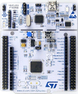
The following figure shows the demo boards.
- NUCLEO-F103RB
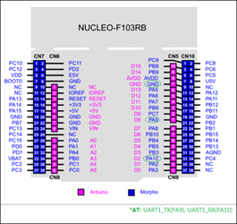
The following figure shows pins for the demo board.
- SIM800C mini v2.0
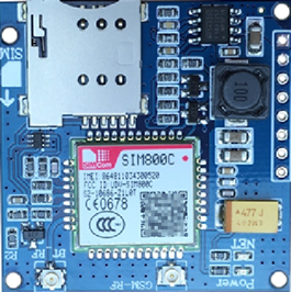
The following figure shows pins for the demo board.
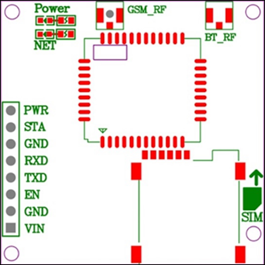
Pin Description PWR Power switch. Automatic power-on is enabled by default. STA Status. GND Ground. RXD Receive data. TXD Transmit data. EN Enable. VIN 5 V to 18 V input.
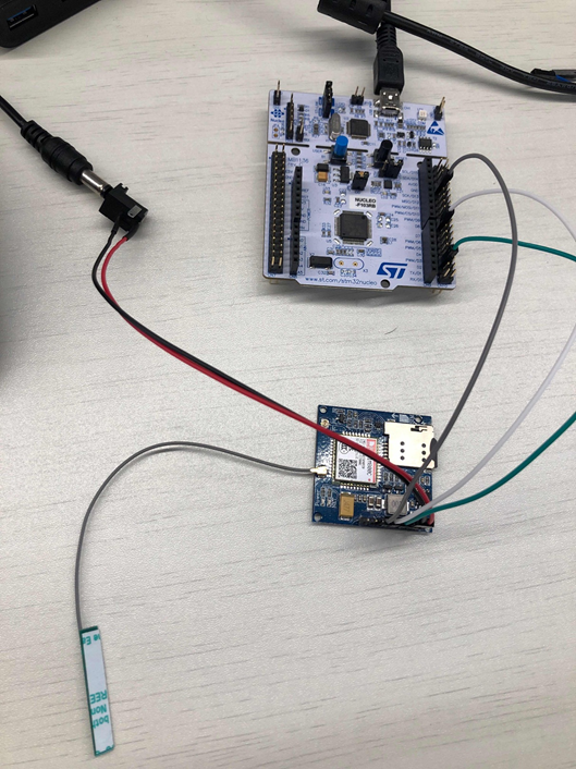
Connect demo boards
Connect the RXD pin of a demo board to the TXD pin of the other demo board. This allows you to establish a connection and run AT commands. The following figure shows how to connect the demo boards.
Build a development environment
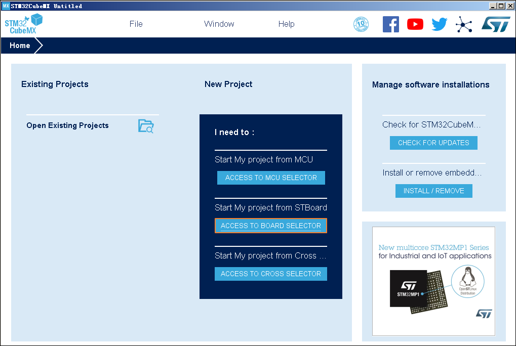
This section uses the STM32CubeMX tool as an example. For more information, visit STM32Cube Ecosystem.
- Open the STM32CubeMX tool and click New Project.
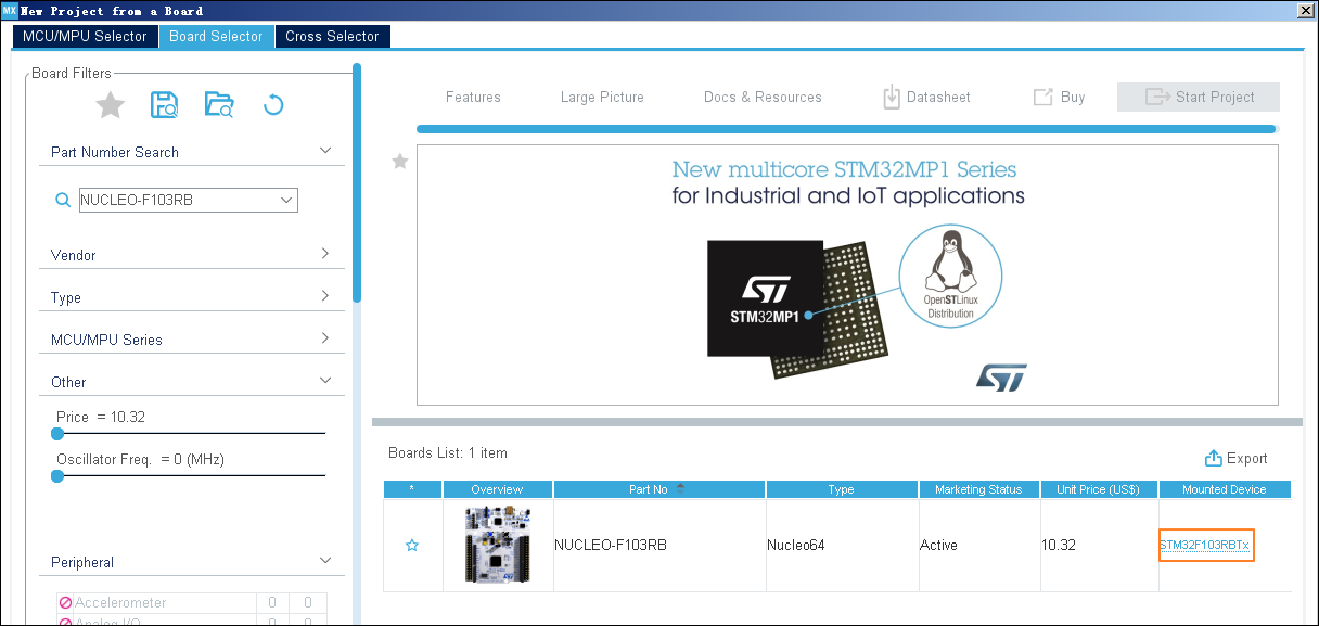
- On the Board Selector tab, search for NUCLEO-F103RB and click STM32F103RBTx.
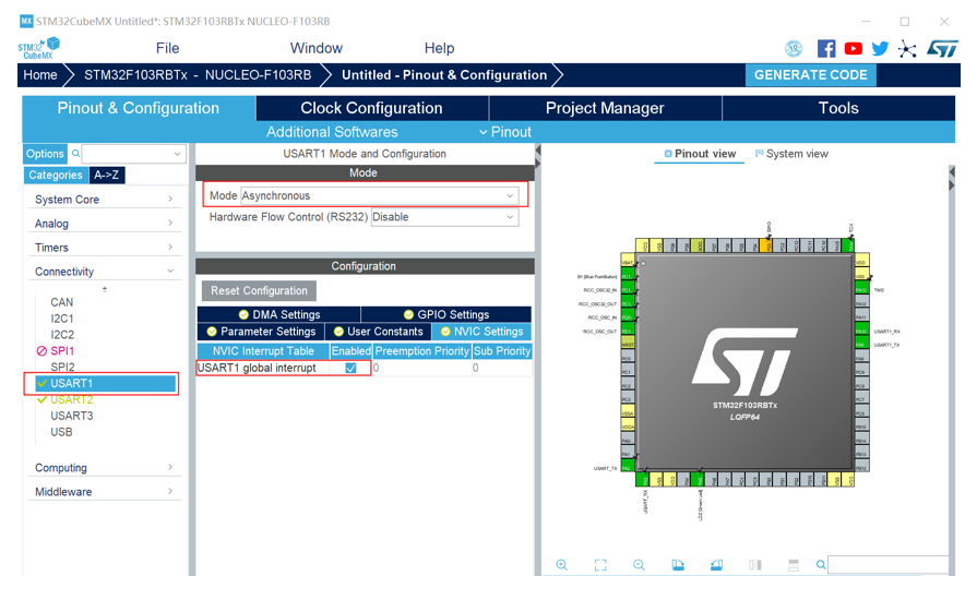
- In the left-side navigation pane, click Connectivity, select USART1 as the port for communication between the MCU and the communication module. Set the
following parameters:
- Set Mode to Asynchronous.
- In the Configuration section, set the following parameters:
- On the GPIO Settings tab, select PA9 and PA10 in the Pin field.
- On the NVIC Settings tab, set USART1 global interrupt to Enabled.
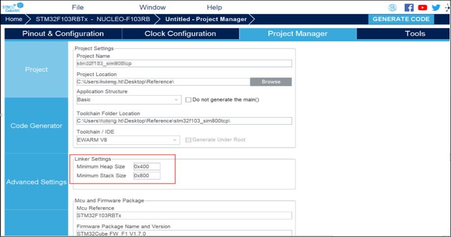
- On the Project Manager tab, specify the required parameters in the Project section.
- Set Toolchain/IDE to EWARM V8.
- Set Heap/Stack size based on your business requirements.