Response orchestration provides system components to define input and output parameters for playbooks and build basic playbook workflows.
Start/end
Every workflow must have a Start and an End node. A workflow can have only one Start node but multiple End nodes.
The Start node uses event as its default name. To avoid naming conflicts, do not use "event" as the name for any other component when orchestrating a playbook.
Output gateways
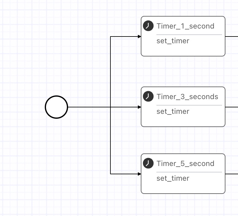
Gateways control the execution branches and flow of a workflow. The following figure shows an example workflow.
|
Name |
Execution logic |
Description |
|
Default output gateway |
Outputs from one node to multiple downstream branches and executes all branches. |
No component is required. Connect the nodes directly using connection lines. Note
Condition configuration is not supported. |
|
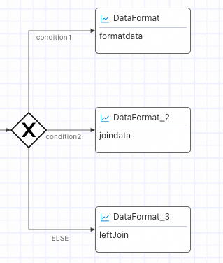
Single output (exclusive gateway) |
When a workflow has multiple branches, it executes only the first branch that meets the specified condition. |
Select the single output component and complete the condition configuration. Note
A default ELSE condition is provided for all cases that do not meet any of the custom conditions. |
|
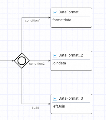
Multiple output |
When a workflow has multiple branches, it executes all branches that meet the specified conditions. |
Select the multiple output component and complete the condition configuration. |
Default output gateway
Configuration instructions
Click a node and use a connection line to directly connect the current component node to its downstream branch nodes. Condition configuration is not supported.
Single output (exclusive gateway)
Configuration instructions
-
From the basic nodes area, drag the Single output component onto the flow editor canvas.
-
Click the Single output component. On the basic information tab on the right, click Configure to open the condition configuration page. After configuring the conditions, click OK to save them.
Based on your business scenario, click ADD IF or AND ELSE IF to add a condition group. Each condition group corresponds to one workflow branch. For more information, see Component condition configuration. You can rename the condition groups to make them easier to understand and distinguish.
-
Configure the gateway connection lines.
-
Hover over the single output gateway icon, and then click a connection point to connect to a branch node.

-
Click a connection line. In the configuration panel on the right, select a condition configured in Step 2 from the drop-down list.
Important-
A default ELSE condition is provided for cases that do not meet any of the custom conditions.
-
Select a different condition for each connection line.
-
-
Multiple output
Configuration instructions
-
From the basic nodes area, drag the Multiple output component onto the flow editor canvas.
-
Click the Multiple output component. On the basic information tab on the right, click Configure to open the condition configuration page. After configuring the conditions, click OK to save them for branch selection.
Based on your business scenario, click ADD IF to add a condition group. Each condition group can correspond to multiple workflow branches. For more information, see Component condition configuration. You can rename the condition groups to make them easier to understand and distinguish.
-
Configure the gateway connection lines.
-
Hover over the multiple output gateway icon, and then click a connection point to connect to a branch node.
-
Click a connection line. In the configuration panel on the right, select a condition that you configured in Step 2 from the drop-down list.
NoteYou can select the same condition for different connection lines.
-
Input gateways
There are two types of input gateways. When branches execute normally, the two gateways function identically. The difference lies in how they handle branch execution failures.
|
Name |
Execution logic |
Description |
|
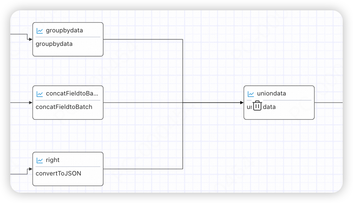
Default input gateway |
Continues execution after all upstream branches are complete. Execution proceeds even if a branch fails. |
No component is required. Connect nodes directly using connection lines. |
|
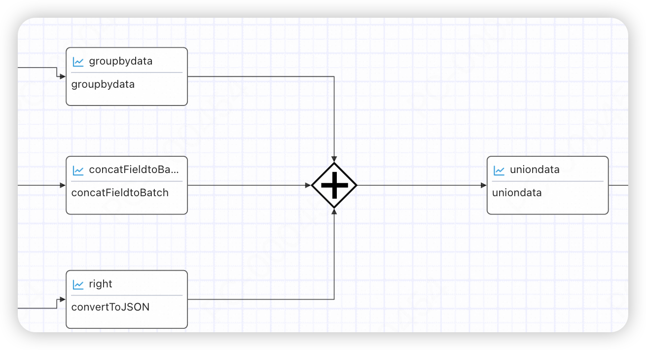
Converging gateway |
Waits for all upstream nodes to complete, then checks whether all "must-pass" upstream branches were executed. If so, it triggers downstream nodes. Otherwise, the node execution fails. |
|
Default input gateway
Configuration instructions
Click a node and use a connection line to directly connect it to its downstream branches.
Converging gateway
Configuration instructions
-
From the basic nodes area, drag the Converging component onto the flow editor canvas.
-
Configure the gateway connection lines.
-
Click a node and use a connection line to directly connect it to the Converging component.
-
Click the connection line, and in the configuration panel on the right, select "must-pass" or "optional" from the drop-down list.
NoteIf you select "must-pass," the node on the current path must be executed. Otherwise, subsequent nodes will not be triggered.
-
Child flow
-
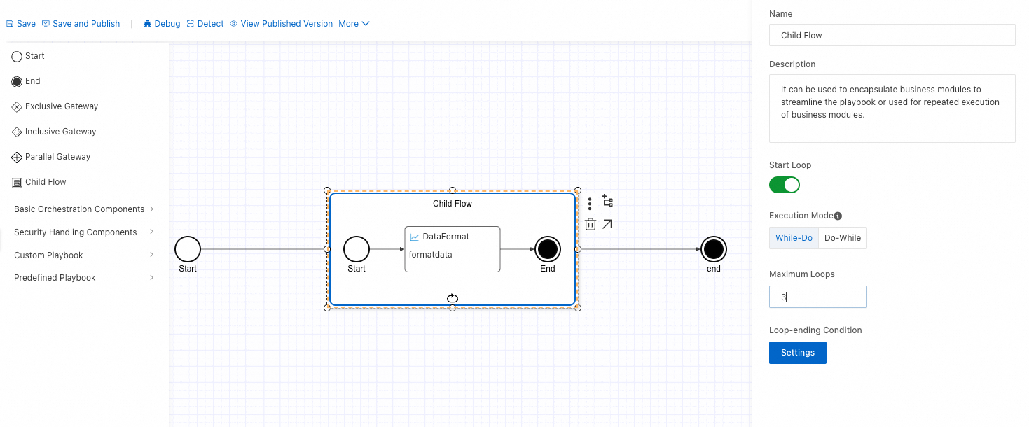
Like a standard workflow, a child flow also requires Start and End nodes. You can use a child flow to group complex workflows, making them clearer and easier to understand. Child flows also support loops.
-
Child flows and parent flows share the same variable scope. The child flow can use data from the parent flow, including inputs, return values from upstream nodes, and variables. Any modifications to variables within the child flow affect the parent flow's results.
-
Nodes outside the child flow can access the result from the last execution of the child flow's internal nodes.
Child flow loop
-
Click the Enable loop button.
-
Loop mode: Do-while: Executes the loop body first, then checks the condition. while-do: Checks the condition before executing the loop body.
-
Maximum loop count: Set the maximum number of loops to prevent infinite loops.
-
Set the loop exit condition: The parameters of all internal nodes from each execution of the child flow can be used as the condition. For parameter configuration, see Component condition configuration.
Loop completion logic
Each loop iteration is considered complete only when all of its executable nodes have finished.
For example, if a "Notify 2" node has finished and reached an End node, but a "Delay" node is still running, the current loop iteration waits for all executable nodes to finish before starting the next one.
Default loop parameters
A child flow provides default parameters, which allow internal components to retrieve information about the current loop.
-
Loop count: Starts from 1. Format: ${child_flow_name.curLoop}.
-
Loop index: Starts from 0. Format: ${child_flow_name.curIndex}.
Example:
When you compose an email using the NotifyMessage component in a child flow, you can use the loop index to retrieve an array parameter value from the Start node.
Component conditions
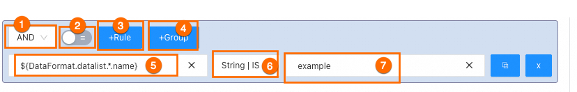
In scenarios such as single output gateways, multiple output gateways, child flow loop exits, and filter components, you must configure conditions to determine the execution flow. SOAR provides a common configuration interface with the following rules:
|
Number |
Description |
|
1 - Logical operator |
AND: All conditions must be met. OR: At least one of the conditions must be met. Important
The logical operator only determines the logical relationship between rules within the same group. |
|
2 - Negation switch |
Negates the condition evaluation for the current group. |
|
3 - Add rule to group |
Adds a rule to the group. The logical relationship between multiple rules in a group is determined by the 1 - Logical operator in the top left corner. |
|
4 - Add condition group |
Adds a group of filter conditions. Important
The relationship between different groups is always AND and is not affected by the 1 - Logical operator. |
|
5 - Condition field |
Supports expressions and constants, typically an output field from a preceding node. |
|
6 - Condition judgment rule |
Supports operations such as IN and = for strings (String), numbers (Number), and observation lists. For more information, see the documentation for the filter component. |
|
7 - Condition value |
Supports expressions and constants. |
Configuration example
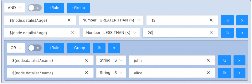
In the example above, the condition is met if the name field of the node is 'john' or 'alice' AND the age field is between 12 and 20 (inclusive).
Condition judgment rules
|
Rule |
Description |
Remarks |
|
NOT IN IP Dataset |
Not in the IP observation list. |
Before you can select an observation list, you must first configure it in Security Center > Agentic SOC > Integration Center > Observation Lists. |
|
IN IP Dataset |
In the IP observation list. |
|
|
NOT IN Dataset |
Not in the observation list. |
|
|
IN Dataset |
In the observation list. |
|
|
String| equals |
Checks if the string equals the specified value. |
None |
|
String| not equal to |
Checks if the string does not equal the specified value. |
None |
|
String| contains |
Checks if the string contains the specified value. |
Example: 'abc' contains 'bc'. |
|
String| does not contain |
Checks if the string does not contain the specified value. |
Example: 'abc' does not contain 'd'. |
|
String| starts with |
Checks if the string starts with the specified value. |
Example: 'abc' starts with 'ab'. |
|
String| ends with |
Checks if the string ends with the specified value. |
Example: 'abc' ends with 'bc'. |
|
String| does not end with |
Checks if the string does not end with the specified value. |
Example: 'abc' does not end with 'ab'. |
|
String| regex match |
Checks if the string matches the specified regular expression. |
Example: 'abcabc' matches the regex '(abc)+'. |
|
String| not regex match |
Checks if the string does not match the specified regular expression. |
Example: 'abab' does not match the regex '(abc)+'. |
|
String| is empty |
Checks if the string is empty. |
Empty strings (''), null, and NULL are all considered empty. |
|
String| is not empty |
Checks if the string is not empty. |
None |
|
Number| equals |
Checks if the number is equal to the specified value. |
None |
|
Number| not equal to |
Checks if the number is not equal to the specified value. |
None |
|
Number| greater than |
Checks if the number is greater than the specified value. |
None |
|
Number| greater than or equal to |
Checks if the number is greater than or equal to the specified value. |
None |
|
Number| less than |
Checks if the number is less than the specified value. |
None |
|
Number| less than or equal to |
Checks if the number is less than or equal to the specified value. |
None |
|
Number| in range |
Checks if the number falls within the configured range. Format: number,number. |
Example: 1 is in the range -1,5. |