This tutorial shows how to use Smart Access Gateway (SAG) as a backup for an Express Connect circuit to connect an on-premises network to Alibaba Cloud, creating a highly available hybrid cloud environment.
Prerequisites
-
A VPC is created in the China (Beijing) region. For more information, see Create and manage a VPC.
-
A Cloud Enterprise Network (CEN) instance is created and the VPC in the China (Beijing) region is attached to the CEN instance. For more information, see Create a CEN instance.
-
An Express Connect circuit is connected to your on-premises network in the China (Beijing) region and a VBR instance is created. For more information, see Connect to an Express Connect circuit in classic mode or Connect to a shared Express Connect circuit.
Background
An enterprise has applications in a VPC in the China (Beijing) region and has connected its on-premises network to the VPC using an Express Connect circuit. To ensure high availability, the enterprise wants to use an SAG instance as a backup for the Express Connect circuit.
-
An SAG-1000 device is deployed in one-arm mode to connect the on-premises network to Alibaba Cloud. This deployment mode requires no changes to the existing network topology.
-
The on-premises network, SAG instance, and VBR instance use BGP to learn and exchange routes. This simplifies network management and operations.
-
The SAG instance is attached to a Cloud Connect Network (CCN) instance and a VBR instance. Both the CCN and VBR instances are attached to the same CEN instance to enable communication with the VPC.
-
When an SAG instance is attached to both a CCN instance and a VBR, CEN prioritizes the Express Connect circuit by default, learning and advertising its routes first. If the Express Connect circuit fails, CEN switches to the routes from the CCN instance. Consequently, all traffic defaults to the Express Connect circuit and fails over to the CCN instance.
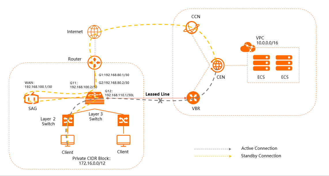
Network plan
Plan your network CIDR blocks based on your business needs and ensure the CIDR blocks do not overlap.
|
Item |
Network configuration |
|
on-premises network |
private CIDR block: 172.16.0.0/12 |
|
|
|
egress router G1 port: 192.168.80.1/30 |
|
|
Smart Access Gateway (SAG) |
WAN port (Port 5): 192.168.100.1/30, Gateway: 192.168.100.2 |
|
BGP:
|
|
|
VBR |
|
|
VPC in China (Beijing) |
VPC CIDR block: 10.0.0.0/16 |
Procedure

Step 1: Purchase an SAG device
After you purchase an SAG device on the SAG console, Alibaba Cloud ships the device to you and creates an SAG instance for device management.
To use an SAG device in a region outside the Chinese mainland, you must purchase the hardware from a third party. For more information, see Purchase SAG devices.
-
Log on to the Smart Access Gateway console.
-
In the left-side navigation pane, click SAG > Instances.
-
On the SAG page, choose .
-
On the Smart Access Gateway page, set the following parameters, and then click Buy Now.
-
Region: The region where the SAG device is used. In this example, select Mainland China.
-
Instance Type: The model of the SAG device. In this example, select SAG-1000.
-
Have SAG Hardware Already: Select whether you already have an SAG device. In this example, select No.
-
Version: The edition of the SAG device. This example uses the default Standard Edition edition.
-
Quantity: The number of SAG devices to purchase. In this example, select 1.
-
Region: The bandwidth region used by the Smart Access Gateway (SAG) device. This region is the same as the region of the SAG device and cannot be modified.
-
Instance Name: The name of the SAG instance.
-
Peak Bandwidth: The peak bandwidth of the network. In this example, select 50 Mbps.
-
Subscription Period: Select a subscription duration.
-
-
Confirm the order information, select the terms of service, and then click Confirm Purchase.
-
In the Receiving Address dialog box, enter your shipping address, and then click Buy Now.
-
On the Pay page, select a payment method and complete the payment.
You can check whether the order is placed on the Smart Access Gateway page. SAG devices will be shipped within two business days after you place the order. To check the shipping updates, perform the following operations:
On the Smart Access Gateway page, find the target SAG instance.
In the Operation column, click the
 icon and select View Shipping Update.
In the Order Updates panel, view the shipping updates.
After a successful order, the status of the SAG instance is To Be Shipped.
Step 2: Activate and connect the SAG device
After you receive the SAG device, verify that all accessories are included. For more information, see SAG-1000 device specifications.
After verifying the device, activate and connect it.
-
Log on to the Smart Access Gateway console.
-
In the top navigation bar, select the region where your SAG instance is deployed.
-
On the Smart Access Gateway page, find the target instance and bind the device to the SAG instance. For more information, see Add a device.
-
After the device is bound, return to the Smart Access Gateway page. In the Operation column of the target instance, click
 > Activate.
 -
In the Activate dialog box, click OK.
-
After the device is activated, connect the SAG device to your on-premises network as shown in the topology diagram.
Use a network cable to connect the WAN port of the SAG device to port G11 of the Layer 3 switch.
This example uses the WAN port (Port 5). If Port 5 on your device is not a WAN port, you can change the port role. For more information, see Assign port roles.
Note-
Only SAG-1000 V2.0 devices support port role assignment.
-
Before you assign port roles, make sure that the SAG device is powered on, has a stable 4G signal, and is connected to Alibaba Cloud.
-
Step 3: Configure the SAG device
After connecting the device, configure it on the Smart Access Gateway console.
Before you begin, ensure the device is powered on, has a stable 4G signal, and is connected to Alibaba Cloud.
-
Log on to the Smart Access Gateway console.
-
Configure the WAN port.
-
Log on to the Smart Access Gateway console.
-
In the top navigation bar, select the target region.
-
On the SAG page, click the ID of the target SAG instance.
-
On the instance details page, click the Device Settings tab.
-
In the left-side pane of the tab, click Manage WAN Ports.
-
In the WAN (Port 5) section, click Edit.
-
In the Configure WAN (Port 5) dialog box, set the following parameters, and then click OK.
-
Connection Type: Select Static IP.
-
IP Address: The IP address of the WAN port. In this example, enter 192.168.100.1.
-
Mask: The subnet mask of the WAN port IP address. In this example, enter 255.255.255.252.
-
Gateway : The IP address of the gateway. In this example, enter 192.168.100.2.
NoteAfter you configure the gateway, the SAG device generates a default route.
-
-
-
Configure BGP.
NoteFor SAG-1000 devices running software version 1.0, there is no dedicated port for Express Connect circuits. When configuring BGP on the SAG web console, do not use the AS number of the Express Connect circuit as the peer AS number. Doing so incorrectly configures the port's interface properties and prevents the SAG device from learning VPC routes through CEN.
-
In the left-side pane, click Manage Routes.
-
In the BGP Protocol Settings section, click Edit.
-
In the Configure BGP Route Protocol dialog box, configure BGP based on your network plan, and then click OK.
-
Local AS: In this example, enter 65435.
-
Router ID: In this example, enter 192.168.2.2.
-
Hold Time: In this example, enter 180 seconds.
-
Keep Alive: In this example, enter 60 seconds.
-
-
-
Enable BGP for the WAN port.
-
In the Dynamic Routing Settings section, click Enable BGP Protocol.
-
In the Change Routing Protocol dialog box, click OK.
-
In the list of ports, find Port 5 (WAN) and click Edit in the Operation column.
-
In the Modify BGP Dynamic Routing Settings dialog box, select BGP Protocol, configure the peer IP and peer AS, and then click OK.
The peer IP and peer AS correspond to the IP address of the G11 port and the BGP AS number of the connected layer 3 switch, respectively.
-
Peer AS: In this example, use 65430.
-
Peer IP: In this example, use 192.168.100.2.
-
After the configuration is complete, the BGP Protocol Settings section shows that the local AS is
65435, the router ID is192.168.2.2, the hold time is180, and the keep-alive time is60. The IP address of Port 5 (WAN) is192.168.100.1, and its routing protocol is set to Enable BGP. -
-
Configure on-premises route synchronization.
-
On the SAG instance details page, click the Network Configuration tab.
-
In the left-side pane, click Method to Synchronize with On-premises Routes.
-
Select Static Routing, click Add Static Route, and then click OK.
Add a static route for the CIDR block of the on-premises network that needs to communicate with the cloud: 172.16.0.0/12.
-
Step 4: Configure the VBR
Configure the VBR instance on the Express Connect console to establish a BGP peer relationship with the layer 3 switch.
-
Configure a BGP group.
-
Log on to the Express Connect console.
-
In the top navigation bar, select the target region.
-
In the left-side navigation pane, click Virtual Border Router(VBR).
-
On the Virtual Border Router(VBR) page, click the ID of the target VBR instance.
-
On the VBR instance details page, click the BGP Groups tab.
-
On the BGP Groups tab, click Create BGP Group and configure the BGP group with the following information.
-
Name: The name of the BGP group. In this example, enter test.
-
Peer ASN: The AS number of the layer 3 switch. In this example, enter 65430.
-
BGP Key: The key for the BGP group. This parameter is not configured in this example.
-
Description: The description for the BGP group. In this example, enter SAGtest.
-
-
Click OK.
-
-
Configure a BGP peer.
-
On the VBR instance details page, click the BGP Peers tab.
-
On the BGP Peers tab, click Create BGP Peer.
-
In the Create BGP Peer panel, configure the BGP peer information, and then click OK.
-
BGP Group: The BGP group to join. In this example, select the BGP group that was just created.
-
BGP Peer IP: The IP address of the BGP peer. In this example, enter 192.168.110.1, which is the IP address of the G12 port of the layer 3 switch.
-
After creation, the new BGP peer record appears in the BGP Peers list. BGP Peer IP is 192.168.110.1, Network Type is ipv4, Peer ASN is 65430, Status is Available, and BGP neighbor underlying status is Idle.
-
Step 5: Configure the switch and router
Configure the layer 3 switch and egress router that connect to the SAG device. The following are sample configurations for a specific vendor. Configurations may vary between manufacturers, so refer to your device's documentation for details.
-
Configure routes for the layer 3 switch.
interface GigabitEthernet 0/11 no switchport ip address 192.168.100.2 255.255.255.252 # Port IP of the switch that connects to the SAG device interface GigabitEthernet 0/12 no switchport ip address 192.168.110.1 255.255.255.252 # Port IP of the switch that connects to the VBR router bgp 65430 bgp router-id 192.168.1.1 network 172.16.0.0 mask 255.240.0.0 # Advertise the private CIDR block of the on-premises network neighbor 192.168.100.1 remote-as 65435 # Establish a BGP peer relationship with the SAG device neighbor 192.168.100.1 timers 60 180 # Configure the Keep Alive and Hold Time for the BGP session neighbor 192.168.110.2 remote-as 45104 # Establish a BGP peer relationship with the VBR exitImportantWhen advertising the on-premises private CIDR block, advertise only the subnets that require VPC communication. Be selective about the routes you advertise over the Express Connect circuit. To prevent routing loops, do not advertise routes learned from the cloud (such as from the VPC, other SAGs, or VBRs) back to the cloud.
-
Configure routes for the egress router.
ip route 192.168.100.0 255.255.255.252 192.168.80.2 # Route from the egress router to the SAG device
Step 6: Configure cloud connections
After configuring the device, configure the cloud network connections to connect your on-premises network to Alibaba Cloud.
-
Create a CCN instance.
-
Log on to the Smart Access Gateway console.
-
In the top navigation bar, select the Mainland China area.
The area of the CCN instance must be the same as the area where the SAG device is used.
-
In the left-side navigation pane, click CCN.
-
On the CCN page, click Create CCN Instance.
-
In the Create CCN Instance panel, configure a name for the CCN instance, and then click OK.
-
-
Attach network instances.
-
In the left-side navigation pane, click Smart Access Gateway .
-
On the SAG page, find the target instance and click Network Configuration in the Operation column.
-
In the left-side pane, click Network Instance Details.
-
On the Network Instance Details tab, click Add Network, select the CCN instance that you created, and then click OK.
-
Similarly, attach the existing VBR instance to the SAG instance. For more information, see Attach a network instance.
When an SAG instance is attached to both a CCN and a VBR instance, traffic from the on-premises network defaults to the Express Connect circuit. If the circuit fails, traffic fails over to the CCN instance, using an encrypted connection over the internet.
-
-
Attach the CCN and VBR instances to the CEN instance. For more information, see Attach a network instance.
After attaching the instances, the on-premises network can communicate with the VPC that is already attached to the CEN instance.
NoteIf your on-premises network, VBR instance, and VPC are in different regions, you must purchase a CEN bandwidth plan and configure a cross-region connection bandwidth to enable communication between network instances in different regions. For more information, see Use a bandwidth plan and Cross-region connection bandwidth.
-
Configure security group rules.
Configure a security group rule for the ECS instances in your VPC. The rule must allow inbound traffic from your on-premises private CIDR block (172.16.0.0/12) to access resources on the instances. For more information, see Add a security group rule.
Step 7: Add a CEN routing policy
Add a routing policy in CEN to control how VPC routes are advertised to the SAG device. This policy is crucial for managing the failover behavior.
With this policy, when the CCN instance learns the VPC route from the VBR, it does not advertise this route to the SAG device. This forces traffic between the on-premises network and the VPC to use the Express Connect circuit. If the Express Connect circuit fails, the CCN can no longer learn the route from the VBR. Instead, it advertises the VPC route it learns from CEN to the SAG device, rerouting traffic through the SAG.
- Log on to the CEN console.
-
On the CEN Instance page, click the ID of the target CEN instance.
-
On the Basic Information tab, click the Transit Router tab, and then click the ID of the transit router connected to the CCN instance.
-
On the transit router details page, click the Route Table tab.
-
On the Route Table tab, click the Route Maps tab.
-
On the Route Maps tab, click Add Route Map.
-
On the Add Route Map page, configure the parameters with the following information, and then click OK.
Parameter
Description
Policy Priority
Enter a priority for the routing policy.
Description
Enter a description for the routing policy.
Region
Mainland China CCN is selected by default and cannot be changed.
Policy direction
Select Outbound Gateway.
Match Conditions
-
Select a network type. Select Source Instance Type.
-
Then, select VBR.
Action policy
Select Allow.
-
Step 8: Verify the connection and failover
-
After completing the configuration, test the failover by disabling the Express Connect port on your layer 3 switch. Verify that the route to the VPC has switched over; the next hop for the VPC route should now point to the SAG instance. Refer to your device manufacturer's manual for commands to view routes.
-
Test network connectivity by accessing a cloud resource in the VPC from a client on your on-premises network.