This topic explains how to use MaxCompute nodes in DataWorks to process data from the user information table ods_user_info_d and the access log table ods_raw_log_d to generate user profile data. You will learn to use DataWorks and MaxCompute to compute and analyze synchronized data, completing a simple data processing task in a data warehouse.
Prerequisite
Before you begin, make sure you have completed the steps in Synchronize data.
1. Build the data processing pipeline
In the Synchronize data step, data was synchronized to MaxCompute. You must now process this data to generate basic user profile data.
-
In the left-side navigation pane of Data Studio, click the
 icon to open the Data Development page. In the Project Directory section, find the workflow you created and click it to open the workflow canvas.
The following table describes the nodes used in this tutorial.
Node type
Node name
Node function
 MaxCompute SQL
dwd_log_info_diSplits raw log data from the
ods_raw_log_dtable into multiple columns in thedwd_log_info_ditable using built-in functions and a user-defined function (UDF) namedgetregion.MaxCompute SQLdws_user_info_all_diAggregates data from the user information table (
ods_user_info_d) and the processed log table (dwd_log_info_di), and then writes the results to thedws_user_info_all_ditable.MaxCompute SQLads_user_info_1dFurther processes data from the
dws_user_info_all_ditable and writes the results to theads_user_info_1dtable to generate basic user profiles. -
Manually drag to draw lines between nodes to configure upstream nodes. The final result is as follows:
 Note
NoteYou can set upstream and downstream dependencies between nodes by manually drawing lines in the workflow. You can also use code parsing in child nodes to automatically identify node dependencies. This tutorial uses the manual approach. For more information about code parsing, see Automatic parsing mechanism.
2. Register a UDF
To ensure that subsequent data processing tasks run properly, you must register a MaxCompute UDF (getregion) to parse the log data structure synchronized to MaxCompute in the Synchronize data step into a table.
-
This tutorial provides the resource required by the function that resolves IP addresses to regions. You only need to download the resource to your computer and upload it to the DataWorks workspace before you register the function.
-
This function is intended only for this tutorial (sample IP resource). To implement IP-to-region mapping in a production environment, obtain a professional IP lookup service from a dedicated provider.
Upload the resource (ip2region.jar)
-
Download ip2region.jar.
NoteThe
ip2region.jarresource is a sample intended only for this tutorial. -
In the left-side navigation pane of Data Studio, click
 to go to the resource management page. Click
  > New Resource > Maxcompute Jar, specify the resource name, and then go to the resource upload page.Note
The resource name does not need to match the uploaded file name.
-
Set Document Source to Local, click Click Upload next to the file content field, and then select the
ip2region.jarfile that you downloaded. -
Set Data Source to the MaxCompute compute resource that you associated in the Prepare the environment step.
-
On the node toolbar, click Save, and then click Publish. Follow the instructions in the deployment panel to deploy the resource to the MaxCompute projects in the development environment and the production environment.
Register a function (getregion)
-
On the resource management page, click
> New Function > Maxcompute Function, specify the function name, and then go to the function registration page. In this tutorial, the function is named getregion. -
On the Register Function page, configure the required parameters. The following table describes only the key parameters for this tutorial. Retain the default values for parameters that are not listed.
Parameter
Description
Function type
Select
OTHER.Data Source
Select the MaxCompute compute resource that you associated in the Prepare the environment step.
Class Name
Enter
org.alidata.odps.udf.Ip2Region.Resource List
Select
ip2region.jar.Description
Converts an IP address to a region.
Command Format
Enter
getregion('ip').Parameter Description
An IP address.
-
On the node toolbar, click Save, and then click Publish. Follow the instructions in the deployment panel to deploy the function to the MaxCompute projects in the development environment and the production environment.
3. Configure data processing nodes
Data processing requires implementing the processing logic for each layer through MaxCompute SQL scheduling. This tutorial provides complete sample SQL code for data processing. You must configure the following nodes in sequence: dwd_log_info_di, dws_user_info_all_di, and ads_user_info_1d.
Configure the dwd_log_info_di node
The sample code for this node uses the function you created to process columns from the upstream table ods_raw_log_d and writes the results to the dwd_log_info_di table.
-
In the left-side navigation pane of Data Studio, click the
icon to open the Data Development page. In the Project Directory section, find the workflow you created and click it to open the workflow canvas. -
On the workflow canvas, hover over the
dwd_log_info_dinode and click Open Node. -
Paste the following code into the node editor.
-
Configure the debug parameters.
On the right side of the MaxCompute SQL node editor, click Run Configuration and configure the following parameters. These parameters are used during the debug run in Step 4 to test the task with the Run Configuration parameters.
Configuration item
Description
Computing Resources
Select the MaxCompute compute resource that you associated in the Prepare the environment step and its corresponding compute quota.
Resource Group
Select the serverless resource group that you purchased in the Prepare the environment step.
Script Parameters
No configuration is required. The sample code in this tutorial uses
${bizdate}to represent the business date. When you debug the workflow in Step 4, set This operation value to a specific constant (for example,20250223). The task will use this constant to replace the variable defined in the code. -
(optional) Configure schedule settings.
For this tutorial, retain the default values for schedule settings. You can click Scheduling Configuration on the right side of the MaxCompute SQL page. For more information about schedule settings parameters, see Schedule settings.
-
Scheduling Parameters: This tutorial has configured scheduling parameters at the workflow level. No additional configuration is required for individual nodes within the workflow. You can use these parameters directly in tasks or code.
-
Scheduling Policy: You can use the Delayed execution time parameter to specify how long a child node should wait before running after the workflow starts running. This tutorial does not set this parameter.
-
-
On the node toolbar, click Save.
Configure the dws_user_info_all_di node
This node aggregates data from the user information table (ods_user_info_d) and the processed log table (dwd_log_info_di), and writes the results to the dws_user_info_all_di table.
-
On the workflow canvas, hover over the
dws_user_info_all_dinode and click Open Node. -
Paste the following code into the node editor.
-
Configure the debug parameters.
On the right side of the MaxCompute SQL node editor, click Run Configuration and configure the following parameters. These parameters are used during the debug run in Step 4 to test the task with the Run Configuration parameters.
Configuration item
Description
Computing Resources
Select the MaxCompute compute resource that you associated in the Prepare the environment step and its corresponding compute quota.
Resource Group
Select the serverless resource group that you purchased in the Prepare the environment step.
Script Parameters
No configuration is required. The sample code in this tutorial uses
${bizdate}to represent the business date. When you debug the workflow in Step 4, set This operation value to a specific constant (for example,20250223). The task will use this constant to replace the variable defined in the code. -
(optional) Configure schedule settings.
For this tutorial, retain the default values for schedule settings. You can click Scheduling Configuration on the right side of the MaxCompute SQL page. For more information about schedule settings parameters, see Schedule settings.
-
Scheduling Parameters: This tutorial has configured scheduling parameters at the workflow level. No additional configuration is required for individual nodes within the workflow. You can use these parameters directly in tasks or code.
-
Scheduling Policy: You can use the Delayed execution time parameter to specify how long a child node should wait before running after the workflow starts running. This tutorial does not set this parameter.
-
-
On the node toolbar, click Save.
Configure the ads_user_info_1d node
This node further processes data from the dws_user_info_all_di table and writes the results to the ads_user_info_1d table to generate basic user profiles.
-
On the workflow canvas, hover over the
ads_user_info_1dnode and click Open Node. -
Paste the following code into the node editor.
-
Configure the debug parameters.
On the right side of the MaxCompute SQL node editor, click Run Configuration and configure the following parameters. These parameters are used during the debug run in Step 4 to test the task with the Run Configuration parameters.
Configuration item
Description
Computing Resources
Select the MaxCompute compute resource that you associated in the Prepare the environment step and its corresponding compute quota.
Resource Group
Select the serverless resource group that you purchased in the Prepare the environment step.
Script Parameters
No configuration is required. The sample code in this tutorial uses
${bizdate}to represent the business date. When you debug the workflow in Step 4, set This operation value to a specific constant (for example,20250223). The task will use this constant to replace the variable defined in the code. -
(optional) Configure schedule settings.
For this tutorial, retain the default values for schedule settings. You can click Scheduling Configuration on the right side of the MaxCompute SQL page. For more information about schedule settings parameters, see Schedule settings.
-
Scheduling Parameters: This tutorial has configured scheduling parameters at the workflow level. No additional configuration is required for individual nodes within the workflow. You can use these parameters directly in tasks or code.
-
Scheduling Policy: You can use the Delayed execution time parameter to specify how long a child node should wait before running after the workflow starts running. This tutorial does not set this parameter.
-
-
On the node toolbar, click Save.
4. Process data
-
Process data.
In the workflow toolbar, click Run, set the values of the parameter variables defined in each node for this run (this tutorial uses
20250223, and you can change the value as needed), click OK, and wait for the run to complete. -
Query the data processing results.
-
In the left-side navigation pane of DataStudio, click
 to open the Data Development page. Then, in the personal folder, click
  to create a
 .sqlfile. Use any file name. -
At the bottom of the page, confirm that the language mode is
MaxCompute SQL.
-
In the SQL editor, enter the following SQL statement to query the record count of the final result table
ads_user_info_1dand verify whether data processing results have been generated.-- You need to modify the partition filter condition to the actual business date of your current operation. In this tutorial, the debug parameter bizdate (business date) configured earlier is 20250223. SELECT count(*) FROM ads_user_info_1d WHERE dt='business date';-
If the query returns data, the data processing is complete.
-
If a query returns a count of zero, ensure the This operation value matches the business date in your query's
dtpartition. To check the value, open the Runtime Logs pane on the right side of the workflow and click View in the Operation column for the run. The run log shows the business date value, for example,partition=[dt=20250223].
-
-
5. Deploy the workflow
Tasks must be deployed to the production environment before they can be automatically scheduled. Follow these steps to deploy the workflow to the production environment.
This tutorial has configured scheduling parameters at the workflow level in Workflow schedule settings. You do not need to configure scheduling parameters for each node individually before deployment.
-
In the left-side navigation pane of Data Studio, click the
icon to open the Data Development page. In the Project Directory section, find the workflow you created and click it to open the workflow canvas. -
On the node toolbar, click Publish to open the deployment panel.
-
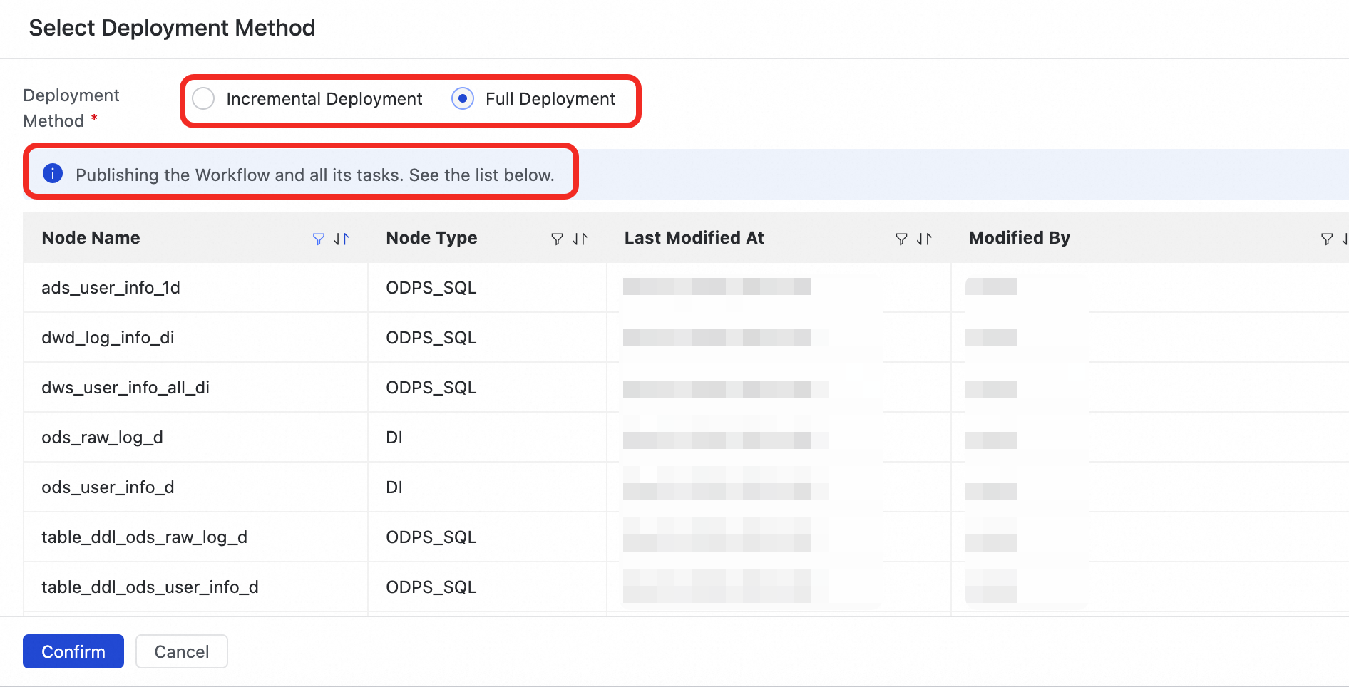
Click Start Release Production. In the deployment method confirmation dialog, select a deployment method based on your needs:
-
Full deployment: Deploys the current workflow and all its tasks.
-
Incremental deployment: Deploys only the current workflow and the internal task nodes whose saved content differs from the current baselines in all deployment environments. This method is suitable for iterative optimization and small-scale updates.
-
-
After you confirm the deployment method, the system automatically deploys the workflow and the selected task nodes to the development environment and the production environment in sequence. When deploying to the production environment, click Confirm Release to complete the deployment.

6. Run tasks in the production environment
After tasks are deployed, instances are generated and run on the next day. You can use Supplementary data to backfill data for the deployed workflow and verify whether the tasks can run in the production environment. For more information, see Backfill data.
-
After the tasks are deployed, click Operation and Maintenance Center in the upper-right corner.
You can also click the
 icon in the upper-left corner and choose .
 -
In the left-side navigation pane, choose to go to the Auto Triggered Node page, and then click the
workshop_startvirtual node. -
In the DAG on the right side, right-click the
workshop_startnode and choose . -
Select the tasks for which you want to backfill data, set the business date, and then click Submit and Redirect.
-
On the backfill data page, click Refresh until all SQL tasks have run successfully.
After you complete this tutorial, to avoid incurring additional costs, you can set the scheduling validity period for the nodes or freeze the root node of the workflow (virtual node workshop_start).
Next steps
-
Visualize data: After user profile analysis is complete, use the Data Analysis module to visualize the processed data as charts for quick insight into key information and business trends.
-
Monitor data quality: Configure data quality monitoring for tables generated by data processing to identify and block dirty data early and prevent the spread of data issues.
-
View metadata: After the user profile analysis workflow is complete, corresponding data tables are created in MaxCompute. You can view the generated tables in the Data Map module and use lineage to view the relationships between tables.
-
Share data through APIs: After the final processed data is available, use the Data Service module to share and apply data through standardized API endpoints, providing data to other business modules that consume data through APIs.