The 3D Earth Container is a component that holds the 3D map and its sub-components, such as sphere, atmosphere, and fly-line layers. It lets you configure the map's rendering mode, background, and viewpoint to render real-time geospatial data from multiple angles and in various formats. This document describes the configuration options for the 3D Earth Container.
Sub-component management
Add sub-components: Click the
 Icon to the left of the 3D Earth to open the Sub-component Panel and the Sub-component Management Panel. In the Sub-component Panel, click to add one or more sub-components. After the sub-components are added, they are displayed in the Sub-component Management Panel.
Copy, delete, and rename sub-components: To copy or delete a sub-component, hover over it, right-click, and select the corresponding option. To rename a sub-component, double-click its name.
For more sub-component management operations, see Manage map sub-components.
Style panel
-
Search Configuration: Click the Style icon
 in the upper right corner of the panel to enter the name of the configuration item you wish to locate in the search field. The system supports fuzzy matching. For more information, see Search configuration item.
 Size: The width and height of the component in pixels (px).
Position: The component's x-coordinate and y-coordinate in pixels (px). The x-coordinate is the horizontal distance from the page's left edge to the component's top-left corner. The y-coordinate is the vertical distance from the page's top edge to the component's top-left corner.
Rotation: The rotation of the component around its center point, in degrees (°).
Enter an angle value to control the component's rotation.
Click the
 icon to flip the component horizontally.
Click the
 icon to flip the component vertically.
Opacity: The value ranges from 0 to 1. A value of 0 is completely transparent, while a value of 1 is fully opaque. The default is 1.
Interaction passthrough: When enabled, mouse interactions pass through this component, preventing it from blocking interactions with other components layered underneath it on a dashboard.
Alignment: The alignment of the component within the editor.
Enable Projection Transformation: Turn on the switch to enable switching between map projection styles.
Projection type: The type of map projection, which can be spherical or Mercator projection. This setting takes effect only after you enable the Enable Projection Transformation option.
Animation Time: Specifies the duration of the animation for projection transitions. The value can range from 0 to 100. This option is available only when the Enable Projection Transform option is enabled.
Rendering mode: This mode provides additional settings for graphics post-processing effects. You can select Advanced mode to enable these settings.
Advanced Rendering Mode
Parameter
Description
Anti-aliasing
The anti-aliasing effect for component rendering. The options include SMAA anti-aliasing, FXAA anti-aliasing, and No anti-aliasing. The default is No anti-aliasing.
Bloom threshold
The threshold for the bloom effect. The value ranges from 0 to 1.
Bloom Radius
The radius of the bloom effect. The value ranges from 0 to 5.
Bloom Intensity
The intensity of the bloom effect. The value ranges from 0 to 1.
Background Settings: The background color of the 3D Earth. To change the color, see Color Picker Instructions.
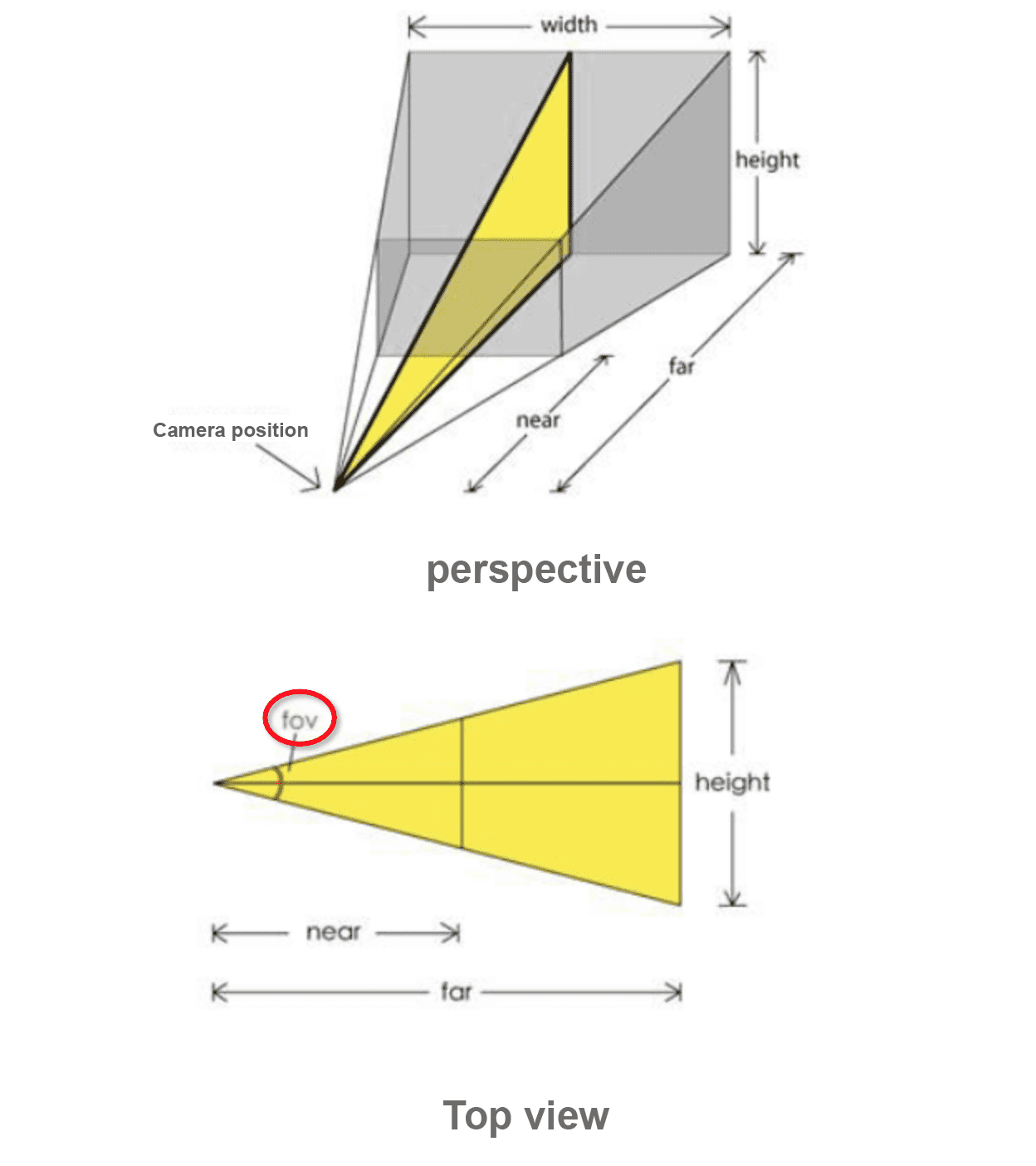
Viewpoint settings: The viewpoint includes four parameters: Perspective, Longitude, Latitude, and Distance. You can adjust these parameters based on camera principles to display the Earth in the visualization application at your desired size and orientation.
Parameter
Description
field of view (fov)
The camera's visible angle. A larger angle makes the Earth appear smaller in the viewport.
Latitude
The latitude of the camera's viewpoint on the globe.
Longitude
The longitude of the camera's viewpoint on the globe.
Distance
The distance from the camera to the globe. A greater distance makes the Earth appear smaller.
Rotation speed: The rotation speed of the Earth. The valid range is 0 to 10. A value of 0 stops the rotation.
Map interaction: Turn on the switch to enable interactive events, such as mouse clicks and zooming, on the preview or published page.
Sub-component Interaction Mode: Sets the interaction mode for sub-components, including Mouse Click and Mouse Move.
Data source panel
This component does not require data configuration.
Advanced panel
This component has no interactive events.
Blueprint interaction
Click the
 icon in the upper-left corner of the page to go to the Blueprint page.
On the Layer node tab, add the current component to the main canvas.
View the Blueprint configuration parameters.

Events: None.
Actions
Actions
Description
Move
Moves the component to a specified position.
    {
      // The movement type. 'to' for absolute positioning, 'by' for relative positioning. Default: 'to'.
        "positionType": "to",
      // The target position, specified by x and y coordinates.
      "attr": {
        "x": 0,
        "y": 0
      },
      // Animation settings.
      "animation": {
        "enable": false,
        // The animation duration in milliseconds.
        "animationDuration": 1000,
        // The animation easing function. Possible values: 'linear', 'easeInOutQuad', or 'easeInOutExpo'.
        "animationEasing": "linear"
      }
    }
Toggle Visibility
Toggles the component's visibility. No parameters are required.
Display
Shows the component. See the code example for animation parameters.
{
  // The animation type. Set to 'fade' for a fade-in effect. Leave empty for no animation.
  "animationType": "",
  // The animation duration in milliseconds (ms).
  "animationDuration": 1000,
  // The animation easing function.
  "animationEasing": ""
}
Hide
Hides the component. See the code example for animation parameters.
{
  // The animation type. Set to 'fade' for a fade-out effect. Leave empty for no animation.
  "animationType": "",
  // The animation duration in milliseconds (ms).
  "animationDuration": 1000,
  // The animation easing function.
  "animationEasing": ""
}
Update Component Configuration
To dynamically update the style configuration of a component, you must first click Copy configuration to clipboard in the component's Style panel to obtain the component configuration data. Then, in a data processing node on the configuration page of the Blueprint editor, modify the field values for the corresponding styles as needed.