This topic describes how to use routing policies to disable communication among virtual private clouds (VPCs) that are attached to the same Cloud Enterprise Network (CEN) instance.
Prerequisites
This feature is supported only by Basic Edition transit routers.
A CEN instance is created. For more information, see Create a CEN instance.
The VPCs are attached to the CEN instance. For more information, see Use a Basic Edition transit router.
Background information
By default, VPCs attached to a CEN instance can communicate with other VPCs, virtual border routers (VBRs), and Cloud Connect Network (CCN) instances that are also attached to the CEN instance. In some scenarios, you may need to disable communication between VPCs, between a VPC and a VBR, or between a VPC and a CCN instance.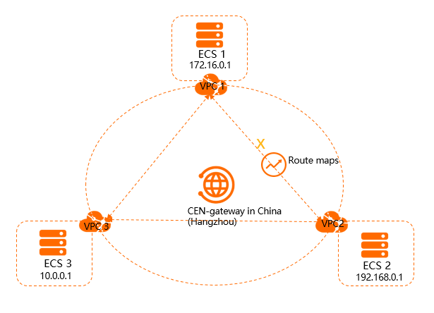
As shown in the preceding figure, VPC1, VPC2, and VPC3 are attached to the CEN instance. By default, VPC1, VPC2, and VPC3 can communicate with each other. If you do not want VPC1 and VPC2 to communicate with each other, you can use a routing policy to disable communication between them. After you add the routing policy, VPC1 and VPC2 can still communicate with VPC3.
Step 1: Add a routing policy that sets VPC2 to reject requests from VPC1
Perform the following steps to configure a routing policy that sets VPC2 to reject requests from VPC1:
Log on to the CEN console.
On the Instances page, click the ID of the CEN instance that you want to manage.
On the instance details page, find the region where you want to add a routing policy and click the ID of the transit router in the region.
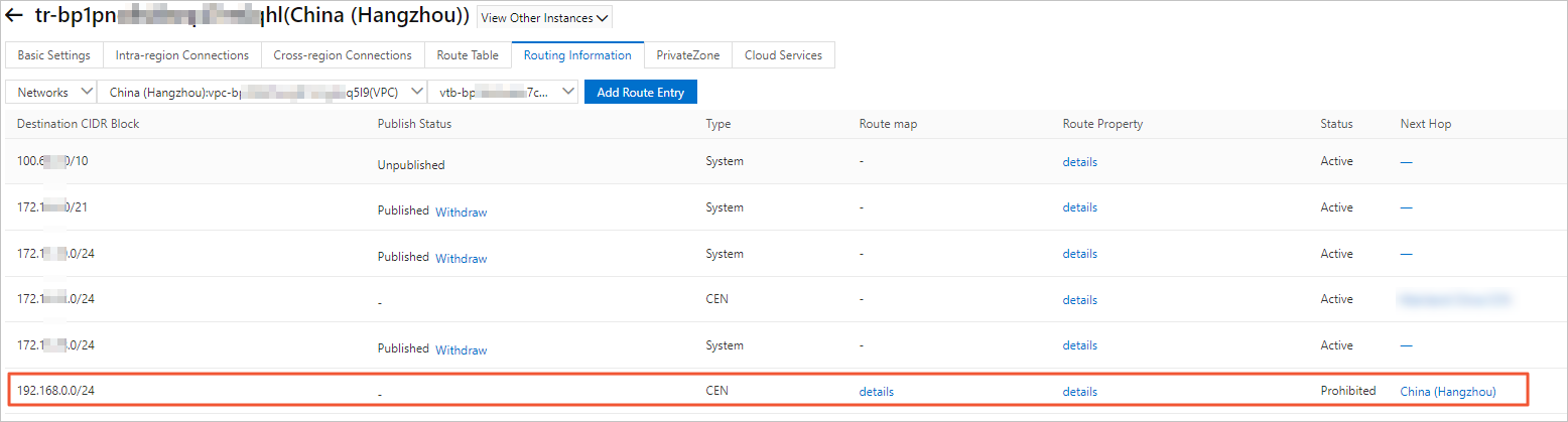
On the details page of the transit router, click the Route Table tab and click Routing Policies.
On the Routing Policies tab, click Add Routing Policy. Set the following parameters and click OK:
Routing Policy Priority: Enter a priority value for the routing policy. A smaller value indicates a higher priority. In this example, 20 is entered.
Region: Select the region to which you want to apply the routing policy. In this example, China (Hangzhou) is entered.
Policy Direction: Select the direction in which you want to apply the routing policy. In this example, Egress Regional Gateway is selected.
Match Conditions: Configure match conditions for the routing policy. In this example, the source instance ID is set to the ID of VPC2 and the destination instance ID is set to the ID of VPC1.
Action Policy: Select the action that you want to perform on routes that meet the match conditions. In this example, Reject is selected.
After you add the routing policy, you can go to the Network Routes tab to check whether VPC2 rejects routes from VPC1.
Step 2: Add a routing policy that sets VPC1 to reject requests from VPC2
Perform the following steps to add a routing policy that sets VPC1 to reject requests from VPC2:
In the left-side navigation pane, click Instances.
On the Instances page, click the ID of the CEN instance that you want to manage.
On the instance details page, find the region where you want to add a routing policy and click the ID of the transit router in the region.
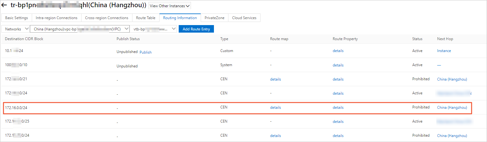
On the details page of the transit router, click the Route Table tab and click Routing Policies.
On the Routing Policies tab, click Add Routing Policy. Set the following parameters and click OK:
Routing Policy Priority: Enter a priority value for the routing policy. A smaller value indicates a higher priority. In this example, 50 is entered.
Region: Select the region to which you want to apply the routing policy. In this example, China (Hangzhou) is entered.
Policy Direction: Select the direction in which you want to apply the routing policy. In this example, Egress Regional Gateway is selected.
Match Conditions: Configure match conditions for the routing policy. In this example, the source instance ID is set to the ID of VPC1 and the destination instance ID is set to the ID of VPC2.
Action Policy: Select the action that you want to perform on routes that meet the match conditions. In this example, Reject is selected.
After you add the routing policy, you can go to the Network Routes tab to check whether VPC1 rejects routes from VPC2.
Step 3: Test network connectivity
Perform the following steps to test the network connectivity between VPC1 and VPC2:
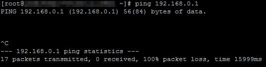
Log on to ECS1 in VPC1.
Run the ping command to ping the IP address of ECS2 in VPC2.
The result shows that ECS1 cannot access ECS2.
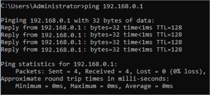
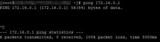
Log on to ECS2 in VPC2.
Run the ping command to ping the IP address of ECS1 in VPC1.
The result shows that ECS2 cannot access ECS1.
Perform the following steps to test the network connectivity between VPC1 and VPC3:
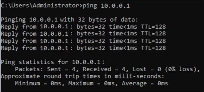
Log on to ECS1 in VPC1.
Run the ping command to ping the IP address of ECS3 instance in VPC3.
The result shows that ECS1 can access ECS3.
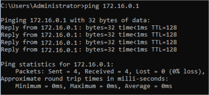
Log on to ECS3 in VPC3.
Run the ping command to ping the IP address of ECS1 in VPC1.
The result shows that ECS3 can access ECS1.
Perform the following steps to test the network connectivity between VPC2 and VPC3:
Log on to ECS2 in VPC2.
Run the ping command to ping the IP address of ECS3 instance in VPC3.
The result shows that ECS2 can access ECS3.
Log on to ECS3 in VPC3.
Run the ping command to ping the IP address of ECS2 in VPC2.
The result shows that ECS3 can access ECS2.