The traffic scheduling feature allows you to mark inter-region network traffic with differentiated services code point (DSCP) values and limit the bandwidth of inter-region connections based on DSCP values. This feature improves network performance because each type of service can be allocated a proper amount of bandwidth resources.
Introduction to traffic scheduling
Overview
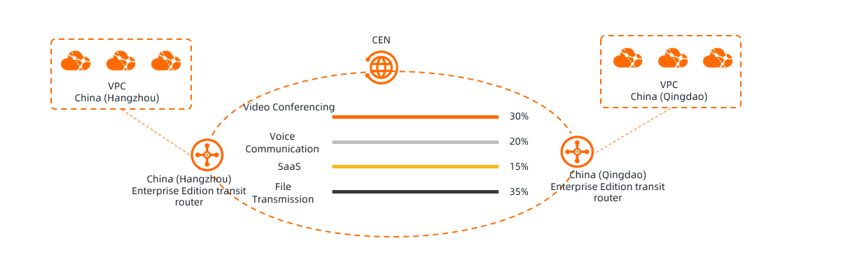
After you use Cloud Enterprise Network (CEN) to establish inter-region communication, traffic from different services, including video conferencing, voice communication, software as a service (SaaS), and file transmission, is transmitted over the inter-region connections. Different service traffic has different requirements for networks, as described in the following examples:
Video conferencing and voice communication require stable networks with low latency. Packet loss and network jitter lower the communication quality.
SaaS requires immediate response. Network congestion decreases user experience.
File transmission requires high network throughput but is insensitive to network performance issues, such as network latency and network jitter. Sufficient bandwidth resources are required if you want to maintain high network throughput.
The maximum bandwidth of a bandwidth plan that is shared by inter-region connections is a fixed value. As a result, different services may compete for bandwidth resources and some services may waste bandwidth resources. This decreases network performance. If file transmission consumes a large percentage of bandwidth resources, network latency during video conferences or voice communication increases. In some cases, network disconnections may occur. To prevent such issues, you can use the traffic scheduling feature to classify network traffic and allocate bandwidth resources to different services. This improves network quality and minimizes network resource waste.
How it works
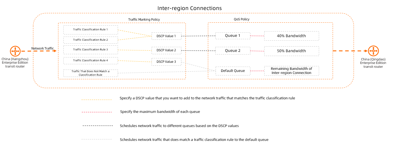
Network traffic is scheduled based on traffic marking policies and quality of service (QoS) policies.
Traffic marking policy
A traffic marking policy captures network traffic based on traffic classification rules and marks the traffic with the Differentiated Services Code Point (DSCP) values that you specify.
When a packet enters an inter-region connection, the packet is matched against the traffic marking policies in descending order of priority. If the packet matches a traffic classification rule in a traffic marking policy, the packet is a match and the DSCP value of the traffic marking policy is added to the packet. If the packet does not match a traffic marking policy, no DSCP value is added to the packet.

Examples
The following table lists the traffic marking policies that are configured for an inter-region connection. When a packet whose source CIDR block is 10.0.10.0/24 and destination CIDR block is 192.168.30.0/24 enters the inter-region connection, the packet is matched against the traffic marking policies, and matches Traffic Classification Rule 3 (Policy 2), which has higher priority. It will not match Rule 5 (Policy 3) Therefore, the DSCP value 9 is added to the packet.
Traffic marking policy
Policy priority
Policy DSCP value
Traffic classification rule
Source CIDR block
destination CIDR block
Traffic Marking Policy 1
5
6
Traffic Classification Rule 1
192.168.10.0/24
192.168.30.0/24
Traffic Classification Rule 2
192.168.20.0/24
192.168.30.0/24
Traffic Marking Policy 2
10
9
Traffic Classification Rule 3
10.0.0.0/16
192.168.30.0/24
Traffic Classification Rule 4
172.16.0.0/16
192.168.30.0/24
Traffic Marking Policy 3
15
12
Traffic Classification Rule 5
10.0.10.0/24
192.168.30.0/24
Traffic Classification Rule 6
10.0.20.0/24
192.168.30.0/24
QoS policy
A QoS policy schedules network traffic to different queues based on the DSCP values that you specify for the traffic marking policies. You can specify a maximum bandwidth value for each queue to prevent services from competing for bandwidth resources.
Each QoS policy contains one default queue. The default queue is used to handle network traffic that fails to match traffic classification rules and network traffic that matches a traffic classification rule but is not scheduled to a queue. The default queue uses the remaining bandwidth resources that are not consumed by the inter-region connections. In each QoS policy, the sum of the bandwidth values of all queues cannot exceed that of the inter-region connections.
Prerequisites
Only inter-region connections created on Enterprise Edition transit routers support the traffic scheduling feature.
Traffic scheduling applies only to outbound traffic on Enterprise Edition transit routers.
If you create an inter-region connection between the China (Hangzhou) region and the China (Qingdao) region, and enable traffic scheduling for the transit router in the China (Hangzhou) region, traffic scheduling applies to the network traffic that flows from China (Hangzhou) to China (Qingdao). Traffic scheduling allocates bandwidth resources to different services. Traffic scheduling does not apply to the network traffic that flows from China (Qingdao) to China (Hangzhou).
ImportantTo ensure that services in both regions have sufficient bandwidth resources, we recommend that you create traffic marking policies and QoS policies for both inbound and outbound traffic.
The following table describes the resource quotas on the traffic scheduling feature.
Item
Default value
Adjustable
The maximum number of traffic classification rules supported by a transit router
500
No
The maximum number of QoS queues supported by a QoS policy
64
No
Examples
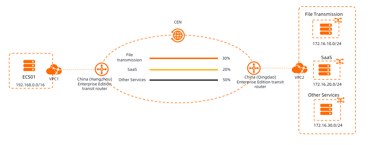
An enterprise created a virtual private cloud (VPC) named VPC1 in the China (Hangzhou) region and another VPC named VPC2 in the China (Qingdao) region. The enterprise used Elastic Compute Service (ECS) to deploy an application named ECS01 in VPC1, and deployed services including file transmission and software as a service (SaaS) services in VPC2. VPC1 is connected to VPC2 through CEN and Enterprise Edition transit routers. However, users may experience high latency and transmission interruptions when they use the file transmission service and SaaS services that are deployed on ECS01 in VPC1. The enterprise found out that other services consumed a large percentage of bandwidth during file transmission over the inter-region connection. As a result, the file transmission and SaaS services do not have sufficient bandwidth resources.
The enterprise decides to use the traffic scheduling feature to regulate bandwidth allocation for the inter-region connection. Traffic scheduling allocates only a specified percentage of bandwidth resources to each service and ensures stable performance of inter-region communication. The following table describes the network settings and bandwidth resources allocated to different services.
Service | Service CIDR block | CIDR block for service communication | Bandwidth (%) |
File transmission | 172.16.10.0/24 | 192.168.0.0/16 | 30% |
SaaS | 2408:****:b440::/64 | 2408:****:a800::/56 | 20% |
Other services | 172.16.30.0/24 | 192.168.0.0/16 | 50% |
Prerequisites
An inter-region connection is created by using CEN and Enterprise Edition transit routers. For more information, see Use CEN and Enterprise Edition transit routers to connect VPCs in different regions and Alibaba Cloud accounts.
Step 1: Create a traffic marking policy
A traffic marking policy captures network traffic based on traffic classification rules and marks the traffic with DSCP values.
Log on to the CEN console.
On the Instances page, click the ID of the CEN instance that you want to manage.
On the tab, click the ID of the transit router on which the inter-region connection is created.
On the details page of the transit router, click the Traffic Marking tab.
On the Traffic Marking tab, click Create Traffic Marking Policy.
On the Create Traffic Marking Policy page, set the following parameters and click OK.
Parameter
Description
Policy Name
Enter a name for the traffic marking policy.
Policy Description
Enter a description for the traffic marking policy.
Priority
Enter a priority for the traffic marking policy. Valid values: 1 to 100. A smaller value indicates a higher priority.
When a packet enters an inter-region connection, the packet is matched against the traffic marking policies in descending order of priority. If the packet matches a traffic classification rule in a traffic marking policy, the packet is a match and the DSCP value of the traffic marking policy is added to the packet. If the packet does not match a traffic marking policy, no DSCP value is added to the packet.
Specified DSCP
After a rule is matched, specify a DSCP value in IP packets to distinguish different traffic.
When you create a QoS policy, you can use the DSCP value to schedule network traffic to different queues.
Valid values: 0 to 63. The DSCP value of each traffic marking policy set for a transit router must be unique.
Traffic Classification Rules
You can select Manual or Automatic to create a traffic classification rule.
Manual generation
Parameter
Description
Address Type
Address type of traffic packet. Valid values:
IPv4: Only matches IPv4 traffic.
IPv6: Only matches IPv6 traffic.
If this parameter is left empty, it matches both IPv4 traffic and IPv6 traffic.
Rule Name
Enter a name for the traffic classification rule.
Protocol
Select a protocol to match data packets.
Multiple protocols, such as HTTP, HTTPS, UDP, TCP, and SSH, are supported. The protocols in the console shall prevail.
Source CIDR Block
Enter a source CIDR block to match data packets.
The system matches the source IP addresses of packets against the specified source CIDR block. If you do not set this parameter, it indicates that all source IP addresses are considered a match.
Source Ports
Enter a source port range to match data packets.
The system matches the source ports of packets against the specified source port range. If you do not set this parameter, it indicates that all source ports are considered a match.
Valid values: -1 and 1 to 65535. Formats:
1/200: specifies ports that range from 1 to 200.
80/80: specifies port 80.
-1/-1: specifies all ports.
-1: an invalid value. Only -1/-1 is valid.
Destination CIDR Block
Enter a destination CIDR block to match data packets.
The system matches the destination IP addresses of packets against the specified destination CIDR block. If you do not set this parameter, it indicates that all destination IP addresses are considered a match.
Destination Ports
Enter a destination port range to match data packets.
The system matches the destination ports of packets against the specified destination port range. If you do not set this parameter, it indicates that all destination ports are considered a match.
Valid values: -1 and 1 to 65535. Formats:
1/200: specifies ports that range from 1 to 200.
80/80: specifies port 80.
-1/-1: specifies all ports.
-1: an invalid value. Only -1/-1 is valid.
DSCP
Match the DSCP that already exists in IP packets when they arrive at the TR. If you leave this field empty, the rule matches packets with any DSCP value. If you have not set DSCP in ECS operating systems or in your on‑premises IDC, we recommend that you do not configure this field.
ImportantDifference between the DSCP values in policies and rules:
DSCP value in a marking policy: The TR re‑marks the DSCP field of all traffic that matches the classification rules. This overwrites any existing DSCP value in the IP packets. You can then use this DSCP value to classify traffic into queues when you create traffic scheduling policies.
DSCP value in a classification rule: Match traffic that has already been marked on ECS instances in the cloud or in your on‑premises IDC. To mark the DSCP field of packets on ECS instances, you can use the Linux
tc.
6-tuple Description
Enter a description for the traffic classification rule.
Automatic generation
This method allows you to specify the CIDR block of a VPC as the source CIDR block or destination CIDR block. You only need to set the Source CIDR Block and Destination CIDR Block parameters and click Automatically Generate Rules. Then, the system automatically sets the Protocol, Source Port, Destination Port, and DSCP parameters.
Set Method to Automatic, set the Rule Name, Source CIDR Block, and Destination CIDR Block parameters, and then click Automatically Generate Rules.
ImportantAfter you click Auto Generate, you must select the generated rule and click OK at the bottom of the page before the system can apply the generated rule. After you click Auto Generate, if you click OK without selecting the generated rule, the rule is not applied.
If you want to create more traffic classification rules, add the source and destination CIDR blocks to the Source CIDR Block and Destination CIDR Block parameters and click Auto Generate. Then, the system generates and lists all traffic classification rules based on the specified source CIDR blocks and destination CIDR blocks. You can select the traffic classification rules that you want.
After you click Auto Generate, if you want to modify a traffic classification rule, modify the Rule Name, Source CIDR Block, and Destination CIDR Block parameters. Then, click Auto Generate, and select the rules that you want to apply.
Parameter
Description
Rule Name
Enter a name for the traffic classification rule.
Source CIDR Block
Enter source CIDR blocks for the traffic classification rule.
Click Quick Add on the right side. In the Source CIDR Block dialog box, select the CIDR block of VPC from the left-side drop-down list, click the
 icon to add the CIDR block, and then click OK.
 If you want to remove it, select the CIDR block from the right-side drop-down list and click the
 icon in dialog box.
 Destination CIDR Block
Enter destination CIDR blocks for the traffic classification rule.
Click Quick Add on the right side. In the Destination CIDR Block dialog box, select the CIDR block of VPC from the left-side drop-down list, click the
icon to add the VPCs, and then click OK. If you want to remove it, select the CIDR block from the right-side drop-down list and click the
icon in dialog box. Protocol
The Protocol, Source Port, Destination Port, and DSCP parameters are automatically configured and cannot be modified. The following parameters are automatically configured:
Protocol: matches all protocols by default.
Source Port: matches all ports by default.
Destination Port: matches all destination ports by default.
DSCP: matches all DSCP values by default.
Source Port
Destination Port
DSCP
Repeat Step 3 to Step 6 to create a traffic marking policy for the transit router in the peer region.
In this example, a traffic marking policy is manually created for each of the China (Hangzhou) and China (Qingdao) regions. The following table describes the parameters.
NoteIn the following table, N/A indicates that the parameter is ignored and the default match rule is applied.
Region
China (Hangzhou)
China (Qingdao)
Parameter
Traffic Marking Policy 1
Traffic Marking Policy 2
Traffic Marking Policy 3
Traffic Marking Policy 1
Traffic Marking Policy 2
Traffic Marking Policy 3
Policy Name
File
SaaS
Other
File
SaaS
Other
Priority
5
10
15
5
10
15
Specified DSCP
5
10
15
5
10
15
Traffic classification rule
Address Type
N/A
IPv6
N/A
N/A
IPv6
N/A
Protocol
N/A
HTTP
HTTPS
N/A
HTTP
HTTPS
Source CIDR Block
192.168.0.0/16
2408:****:a800::/56
192.168.0.0/16
172.16.10.0/24
2408:****:b440::/64
172.16.30.0/24
Source Port
1/200
N/A
1/200
25/25
80/80
443/443
Destination CIDR Block
172.16.10.0/24
2408:****:b440::/64
172.16.30.0/24
192.168.0.0/16
2408:****:a800::/56
192.168.0.0/16
Destination Port
25/25
80/80
443/443
1/200
N/A
1/200
DSCP
25
30
N/A
25
30
N/A
Traffic marking policy
Matches packets that are from 192.168.0.0/16 and port 1 to port 200, are destined for 172.16.10.0/24 and port 25, and carry a DSCP value of 25. A DSCP value of 5 is added to such packets.
Matches packets that use HTTP, are from 2408:****:a800::/56, are destined for 2408:****:b440::/64 and port 80, and carry a DSCP value of 30. A DSCP value of 10 is added to such packets.
Matches packets that use HTTPS, are from 192.168.0.0/16 and port 1 to port 200, and are destined for 172.16.30.0/24 and port 443. A DSCP value of 15 is added to such packets.
Matches packets that are from 172.16.10.0/24 and port 25, are destined for 192.168.0.0/16 and port 1 to port 200, and carry a DSCP value of 25. A DSCP value of 5 is added to such packets.
Matches packets that use HTTP, are from 2408:****:b440::/64 and port 80, are destined for 2408:****:a800::/56, and carry a DSCP value of 30. A DSCP value of 10 is added to such packets.
Matches packets that use HTTPS, are from 172.16.30.0/24 and port 443, and are destined for 192.168.0.0/16 and port 1 to port 200. A DSCP value of 15 is added to such packets.
Step 2: Create a QoS policy
Create queues based on the DSCP values, and specify a maximum bandwidth value for each queue.
Log on to the CEN console.
On the Instances page, click the ID of the CEN instance that you want to manage.
On the tab, click the ID of the transit router on which the inter-region connection is created.
On the details page of the transit router, click the Cross-region Connections tab.
On the Cross-region Connections tab, find the inter-region connection that you want to manage and click Set in the QoS Policy column.
On the Configure Cross-region QoS Policy page, configure the parameters and click OK. The following table describes the parameters.
Parameter
Description
Policy Name
Enter a name for the QoS policy.
Policy Description
Enter a description for the QoS policy.
Inter-region Connection
Select the inter-region connection for which you want to apply the QoS policy.
Guaranteed Bandwidth Allocation Mode
Set the guaranteed bandwidth allocation mode to by percentage or by absolute value.
NoteYou can select the guaranteed bandwidth allocation mode when creating a QoS policy. To modify the mode, you must delete the existing QoS policy and create a new one.
Queues
Queue Name
Enter a name for the queue.
Queue Description
Enter a description for the queue.
Matching DSCP
Enter a DSCP value to match data packets.
The DSCP value refers to the one that you want to add to data packets which match the traffic marking policy. The DSCP value is the same as the one specified for the DSCP parameter when you create the traffic marking policy. Data packets that match the specified DSCP value are scheduled to the current queue.
You can specify multiple DSCP values for a queue. Separate DSCP values with commas (,).
Throttling Bandwidth
Enter the maximum bandwidth of the queue.
Measured in % when Guaranteed Bandwidth Allocation Mode is set to by percentage. A value of 30 specifies that the current queue can consume at most 30% of the total bandwidth of the inter-region connection.
Measured in Mbps when Guaranteed Bandwidth Allocation Mode is set to by absolute value. A value of 30 specifies the maximum bandwidth of the inter-region connection for the queue is 30Mbps.
Repeat Step 3 to Step 6 to create a QoS policy for the transit router in the peer region.
The following table describes the QoS policies created for the transit routers in the China (Hangzhou) and China (Qingdao) regions.
Region
Policy Name
Inter-region Connection
Guaranteed Bandwidth Allocation Mode
Queue
Queue Name
Matching DSCP
Throttling Bandwidth (in percentage: 30 specifies 30% of the total bandwidth of the inter-region connection)
China (Hangzhou)
QoS-Policy-HZ
Select the inter-region connection that connects the China (Hangzhou) region to the China (Qingdao) region.
Select by percentage
Queue-File
5
30
Queue-SaaS
10
20
Queue-Other
15
50
China (Qingdao)
QoS-Policy-QD
Queue-File
5
30
Queue-SaaS
10
20
Queue-Other
15
50
After you complete the preceding steps, the QoS policies allocate bandwidth resources based on the maximum bandwidth value specified for each queue.
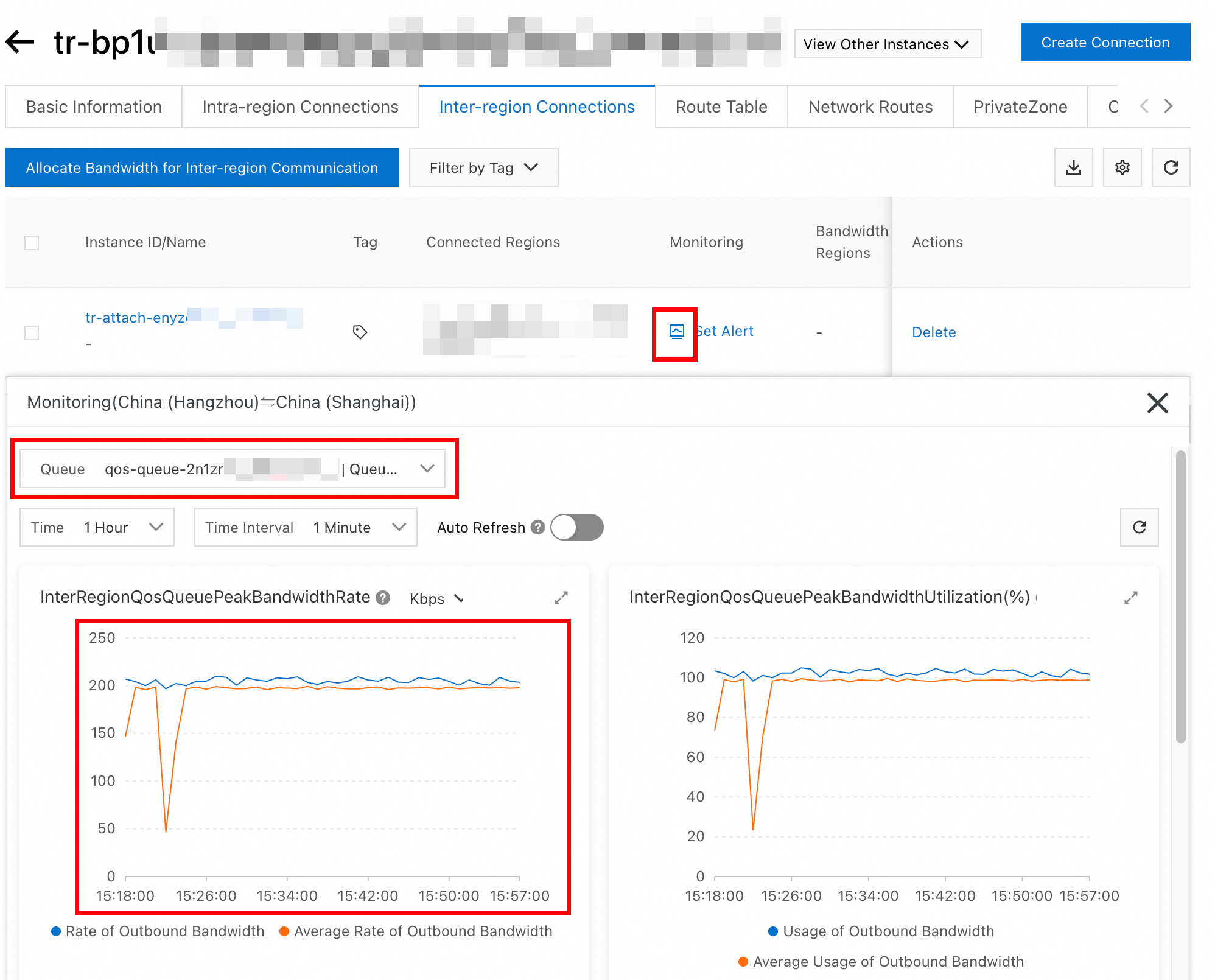
Step 3: Authenticate the traffic that hits the queue
In the Monitoring column for the destination inter-region connection, click the ![]() icon. From the Queue drop-down list, select the destination queue. If a traffic trend appears, the traffic is successfully scheduled.
icon. From the Queue drop-down list, select the destination queue. If a traffic trend appears, the traffic is successfully scheduled.
What to do next
Modify a traffic marking policy
After you create a traffic marking policy, you can modify the name and description of the policy, and add or delete traffic classification rules for the policy. You cannot modify the priority or DSCP values of the policy.
Log on to the CEN console.
On the Instances page, click the ID of the CEN instance that you want to manage.
On the tab, click the ID of the transit router on which the inter-region connection is created.
On the details page of the transit router, click the Traffic Marking tab, find the traffic marking policy that you want to manage, and then click Edit in the Actions column.
In the Traffic Marking Policy Details panel, enter a name and description for the traffic marking policy and specify a traffic classification rule for the traffic marking policy.
You can only add or delete a traffic classification rule, but cannot modify a traffic classification rule. If the settings of a traffic classification rule cannot meet your requirements, you can delete the rule and add a new one.
Delete a traffic marking policy
You must delete all the traffic classification rules before you can delete a traffic marking policy. The following steps show how to delete a traffic classification rule and a traffic marking policy.
Log on to the CEN console.
On the Instances page, click the ID of the CEN instance that you want to manage.
On the tab, click the ID of the transit router on which the inter-region connection is created.
On the details page of the transit router, click the Traffic Marking tab, find the traffic marking policy that you want to manage, and then click Edit in the Actions column.
In the Traffic Marking Policy Details panel, find the traffic classification rule that you want to manage in the Traffic Classification Rules section, and click Delete in the Actions column. In the Delete Traffic Classification Rule message, click OK.
Repeat the preceding steps to delete all traffic classification rules that you want to delete from the traffic marking policy.
In the upper-right corner of the Traffic Marking Policy Details panel, click Delete. In the Delete Traffic Marking Policy message, click OK.
Modify a QoS policy
After you create a QoS policy, you can modify the name, description, and queue settings of the policy.
Log on to the CEN console.
On the Instances page, click the ID of the CEN instance that you want to manage.
On the tab, click the ID of the transit router on which the inter-region connection is created.
On the details page of the transit router, click the Cross-region Connections tab, find the inter-region connection that you want to manage, and then click details in the QoS Policy column.
In the Cross-region QoS Policy Details panel, modify the name, description, and queues of the QoS policy.
Delete a QoS policy
You must delete all the queues before you can delete a QoS policy. The following steps show how to delete a queue and a QoS policy.
Log on to the CEN console.
On the Instances page, click the ID of the CEN instance that you want to manage.
On the tab, click the ID of the transit router on which the inter-region connection is created.
On the details page of the transit router, click the Cross-region Connections tab, find the inter-region connection that you want to manage, and click details in the QoS Policy column.
In the Cross-region QoS Policy Details panel, find the queue that you want to manage in the Queues section, and click Delete in the Actions column. In the Delete Queue From QoS Policy message, click OK.
In the upper-right corner of the Cross-region QoS Policy Details panel, click Delete. In the Delete QoS Policy message, click OK.
References
Traffic marking policy
CreateTrafficMarkingPolicy: Creates a traffic marking policy.
AddTrafficMatchRuleToTrafficMarkingPolicy: Adds a traffic classification rule to a traffic marking policy.
RemoveTrafficMatchRuleFromTrafficMarkingPolicy: Deletes a traffic classification rule from a traffic marking policy.
DeleteTrafficMarkingPolicy: Deletes a traffic marking policy.
ListTrafficMarkingPolicies: Queries the information about a traffic marking policy.
QoS policy
CreateCenInterRegionTrafficQosPolicy: Creates a QoS policy for inter-region communication.
CreateCenInterRegionTrafficQosQueue: Create a queue for a QoS policy.
UpdateCenInterRegionTrafficQosPolicyAttribute: Modifies the name and description of a QoS policy.
UpdateCenInterRegionTrafficQosQueueAttribute: Modifies a queue in a QoS policy.
DeleteCenInterRegionTrafficQosQueue: Deletes a queue from a QoS policy.
DeleteCenInterRegionTrafficQosPolicy: Deletes a QoS policy.
ListCenInterRegionTrafficQosQueues: Queries QoS queues.
ListCenInterRegionTrafficQosPolicies: Queries QoS policies.