The Modbus debugging tool tests whether a gateway can connect to a specified Modbus device and whether the Thing Specification Language (TSL) of the product to which the Modbus device belongs is correctly configured.
Prerequisites
- Make sure that you have set up edge instances. For more information, see Set up environments.
- Assign the Modbus driver and sub-devices to the edge instance. For more information, see Modbus drivers.
Procedures
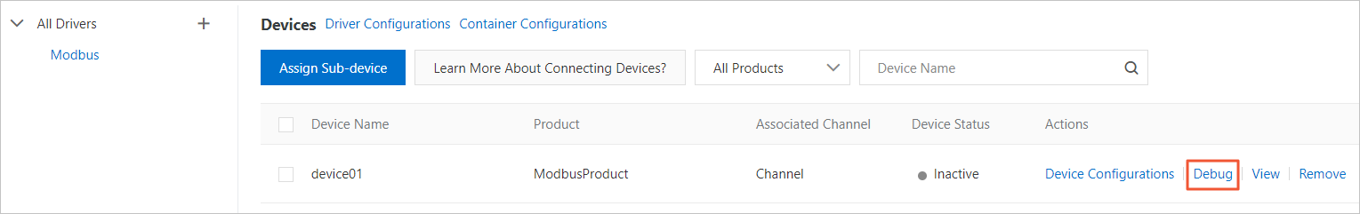
- Log on to the IoT Platform console.
- In the left-side navigation pane, choose .
Find the instance that is assigned a Modbus device and click View.
- On Instance Details page, select the Devices & Drivers tab. In the All Drivers drop-down list, select the Modbus driver. Click Debug to the right of the device name.
Note If the Debug option is dimmed, click Reset in the upper-right corner of the Instance Details page to reset the edge instance.
- On the Channel Debugging page, click Add Property to debug the configurations.
- The following table describes the coil parameters.
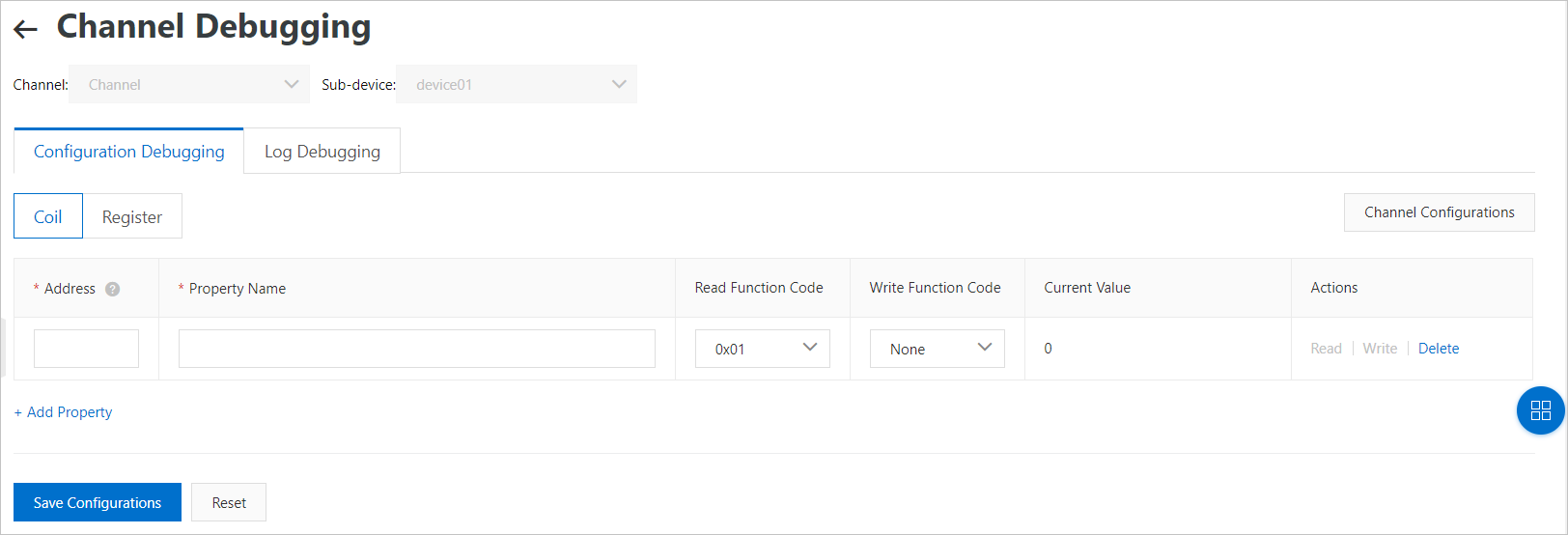
Table 1. Coil parameters Parameter Description Address The address of the coil. The address must be in the hexadecimal format and start with 0x.You must specify the addresses of the coil based on your device properties. For example, if the address of the device temperature is 1 address, set the parameter to
0x1.Property Name The name of the property. Set the property names and save the configuration. On the Define Feature tab of the Product Details page, you can view the property names by selecting the Self-Defined Features filter under the Feature Name column.
Read Function Code The function code that is used to read or input the status of the coil. Write Function Code The function code that is used to write to the coil. Note When the read function code is set to0x02(input state), you cannot perform the write operation.Current Value The measured parameter values of the TSL for the Modbus device. For example, the current values can be the illuminance, temperature, and humidity that are measured. Actions - Read: Sends an instruction to the gateway to read the measured value. The gateway sends a read command to the device and returns the result to the Current Value column.
- Write: Sends the command to the gateway to write the measurement. The gateway sends a write command to the device and updates the Current Value column.
Note When the read function code is set to
0x02(input state), you cannot perform the write operation. - Delete: Removes this coil from the TSL of the product to which the device belongs.
Important After you delete the product and save the configurations, all devices under the product are affected.
- The following table describes the register parameters.
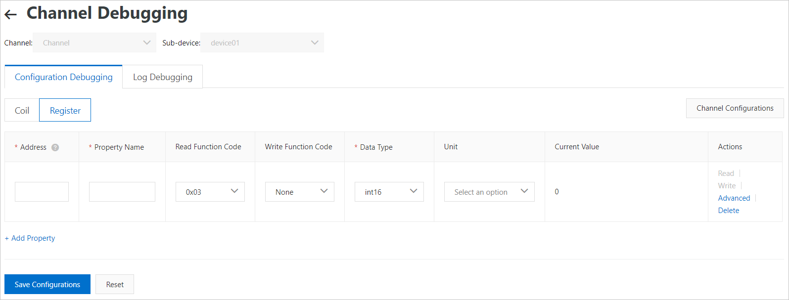
Table 2. Register parameters Parameter Description Address The starting address of the property. The address must be in the hexadecimal format and start with 0x.Important When you add one or more register addresses, the addresses cannot overlap. If the register addresses overlap, an error occurs when you save the configurations.You must specify the addresses of the register based on your device properties. For example, if the device temperature is indicated by 1 in the IP address, set the parameter to
0x1.Property Name The name of the property. Read Function Code The function code that is used to read from the register. Write Function Code The function code that is used to write to the register. Note- When the read function code is set to
0x04(input register), you cannot perform the write operation. - If you want to write data of types other than int16 and uint16 to the holding register, select
0x10function code.
Data type The data type of the register. Valid values: int16, uint16, int32, uint32, int64, uint64, float, and double. Different data types use different numbers of registers. For more information, see the table Number of registers for each data type in the subsequent section. Unit Select the measurement unit for the device. Current Value The measured parameter values of the TSL for the Modbus device. For example, the current values can be the illuminance, temperature, and humidity that are measured. Actions - Read: Sends an instruction to the gateway to read the measured value. The gateway sends a read command to the device and returns the result to the Current Value column.
- Write: Sends the command to the gateway to write the measurement. The gateway sends a write command to the device and updates the Current Value column.
Note When the read function code is set to
0x04(input register), you cannot perform the write operation. - Advanced: configures more register parameters. For parameter descriptions, see the following table Advanced configurations.
- Delete: Removes this register from the TSL of the product to which the device belongs.
Important After you delete the product and save the configurations, all devices under the product are affected.
Table 3. Advanced parameters Parameter Description Swap Bytes This parameter controls the byte order that is used to parse the register information. By default, the big-endian ordering is used. - true: The little-endian ordering is used.
- false: The big-endian ordering is used.
Example 1: When 12345 is written, the corresponding hexadecimal value is 0x3039. If this parameter is set to false, the byte order for sending and receiving the value is 30 39. If this parameter is set to true, the order is 39 30.
Example 2: If you used the 0x10 function code to send the RTU message for writing to the holding register of a device station, which has the slaveID of 1. If this parameter is set to false, the complete message is: 01 10 02 00 01 30 39 f7 E1. If this parameter is set to true, the message is: 01 10 02 00 01 39 3033 14.
Swap Registers This parameter controls the order in which the registers are parsed. The data type must be int16 or uint16. By default, the system treats the registers of lower addresses as the ones having higher bit values. Therefore, higher bit values are sent first and the registers of lower addresses are parsed first. For example, if you send int64 data (0x1234567890ABCDEF) to the device, the data is split into four registers. (Swap Bytes is set to false). If this parameter is set to false, the ordering of the message is 12 34 56 78 90 AB CD EF. If this parameter is set to true, the ordering is CD EF 90 AB 56 78 12 34.
Zoom Factor Sets how the raw data of the device is scaled. When the performance of floating-point operations is poor, you can set the floating points to integers. This parameter allows you to set a factor to scale the original data of the device. For example, when the device uses 1234 to represent 12.34, the scale factor should be set to 0.01. All data values set for the device are automatically multiplied by 100 and sent to the device. When the 12.34 value is set on the cloud or in the console, the driver automatically converts 12.34 to 1234 and sends the resulting data to the device. Conversely, when the device sends messages, 1234 is converted to 12.34 before sending to IoT platform or other devices.
Table 4. Number of registers of each data type Data type Number of registers Description int16 1 The 16-bit signed integer type. uint16 1 The 16-bit unsigned integer type. int32 2 The 32-bit signed integer type. uint32 2 The 32-bit unsigned integer type. int64 4 The 64-bit signed integer type. uint64 4 The 64-bit unsigned integer type. float 2 The single-precision floating-point type (32 bits). double 4 The double-precision floating-point type (64 bits). - When the read function code is set to
- The following table describes the coil parameters.
- After the debugging is completed, click Save configuration to update the functional definition of the product to the server.
The Saved notification appears, indicating that the data has been saved to the server.Note After the configurations are saved, a custom feature is generated. On the Define Feature tab of the Product Details page, you can view the feature by selecting the Self-Defined Features filter for the Feature Name column. The Identifier parameter is automatically generated by the system after the configurations are saved. The identifier is generated by the following rule:
The value of the Identifier column is based on the value of the Identifier parameter in the TSL of the device. The format of the Identifier parameter is
register type_4-bit hexadecimal address. For example, if the read function code in the configurations is set to 01, the register type is coilStatus, the address is set to 0x 00, and the 4-bit hexadecimal address is 0000, then the value of Identifier is coilStatus_0000.
Other operations
- Reset: On the debug page, you can click Reset to reset the current configurations.
- Channel Configurations: You can click Channel Configurations in the upper-right corner of the configuration page to modify the parameters of the Modbus communication channel. You can then click OK to save the changes.
- Log Debugging: On the Channel Debugging page, you can click Log Debugging to view the debugging logs. You can also click Clear Screen to clear the logs on this page.
Function codes for different register and coil types
| Type | Function Code | operateType |
| Coil (coil status) | 0x01 | coilState |
| Input state (input coil) | 0x02 | inputState |
| Holding register | 0x03 | holdingRegister |
| Input register | 0x04 | inputRegister |